Table of Contents
Quick Links
—
A B B M E A S U R E M E N T & A N A LY T I C S | O P E R AT I N G I N S T R U C T I O N
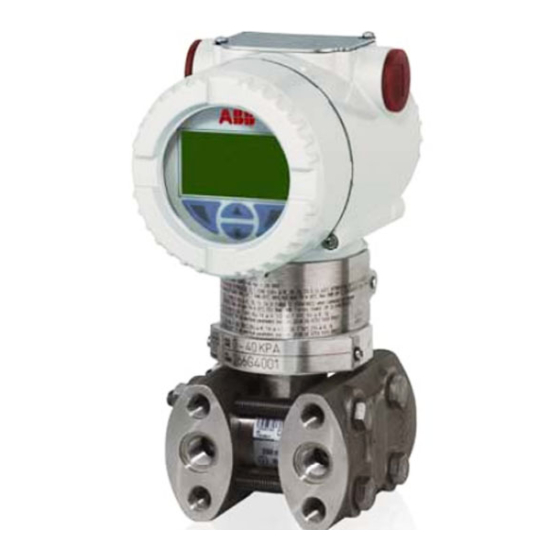
266 HART
Pressure transmitters
—
Introduction
266 models
The 2600T family provides comprehensive range of
top quality pressure measurement products,
specifically designed to meet the widest range of
applications ranging from arduous conditions in
offshore oil and gas to the laboratory environment
of the pharmaceutical industry.
Engineered solutions for all
applications
Measurement made easy
For more information
Further publications for 2600T series pressure
products are available for free download from
www.abb.com/pressure
Table of Contents

Related Manuals for ABB 266 HART Series


Summary of Contents for ABB 266 HART Series
- Page 1 Further publications for 2600T series pressure top quality pressure measurement products, products are available for free download from specifically designed to meet the widest range of www.abb.com/pressure applications ranging from arduous conditions in offshore oil and gas to the laboratory environment of the pharmaceutical industry.
- Page 2 We are an established world force in the design and manufacture of measurement products for industrial process control, flow measurement, gas and liquid analysis and environmental applications. As a part of ABB, a world leader in process automation technology, we offer customers application expertise, service and support worldwide.
-
Page 3: Table Of Contents
Contents Table of contents 1 Introduction ............5 5 Mounting .............. 12 5.1 General ..............12 1.1 Instruction manual structure ........5 5.2 IP protection & designation ........12 1.2 Models covered by this manual ........5 5.3 Mounting the transmitter ........... 12 1.3 Product description ............ - Page 4 Contents 7 Commissioning ............. 32 9 Error messages ............ 61 7.1 Analogue and HART Communication models ..... 32 9.1 LCD Display ............. 61 7.2 Standard setting for normal operation 9.2 Error states and alarms..........61 3.8 mA / 20.5 mA ............32 7.3 Standard setting for error detection (alarm) 10 Maintenance ............
-
Page 5: Introduction
1 Introduction 1 Introduction 1.1 Instruction manual structure The present manual provides information on installing, operating, troubleshooting the 266 pressure transmitter. Every section of the present manual is specifically dedicated to the specific phase of the transmitter lifecycle starting from the receipt of the transmitter and its identification, passing to the installation, to the electrical connections, to the configuration and to the troubleshooting and maintenance operations. -
Page 6: Safety
This makes the manufacturer’s warranty null and void. For safety reasons, ABB draws your attention to the fact that only 2.5 Use of instruction sufficiently insulated tools conforming to EN 60900 may be used. -
Page 7: Operator Liability
Depressurize the pipeline/tank before shipping purposes. opening the transmitter connection. All devices sent back to ABB must be free from any hazardous Corrective maintenance work may only be performed by trained materials (acids, alkalis, solvents, etc.). -
Page 8: Transmitter Overview
3 Transmitter overview 3 Transmitter overview 3.1 Transmitter components overview Figure 1: Differential pressure transmitter components 1 - LCD display with keypad (L1 option) 2 - TTG display with keypad (L5 option) 3 - Integrated digital LCD display (LS option Figure 2: Gauge / absolute pressure transmitter components replacing L9 option PHASED OUT) Important. -
Page 9: Range & Span Consideration
3 Transmitter overview 3.2 Range & Span consideration The 2600T Transmitter Specification Sheets provide all information concerning the Range and Span limits in relation to the model and the sensor code. The terminology currently used to define the various parameters is as follows: URL: Upper Range Limit of a specific sensor. -
Page 10: Opening The Box
In this case, near the CE mark, you will find the number of the notified body (0474) that have verified the compliance. 266 pressure transmitters are in compliance with EMC 2004/108/CE*. The certification plate (ref.A) shown here is issued by ABB S.p.A, 22016 Tremezzina, Italy, with the numbers: —... -
Page 11: Optional Wired-On Sst Plate (I1)
4 Opening the box 4.2 Optional wired-on SST plate (I1) The 266 transmitter can be supplied with the optional “Wired On Stainless Steel plate” (figure 4) which is permanently laser printed with a custom text specified in phase of order. The available space consists in 4 lines with 32 characters per line. -
Page 12: Mounting
5 Mounting specification; no further calibration is required in normal 5.1 General condition. ABB typically configures 266 pressure transmitters Study these installation instructions carefully before proceeding. according to the user requirements. A typical configuration Failure to observe the warnings and instructions may cause a includes: malfunction or personal hazard. -
Page 13: Pressure Equipment Directive (Ped) (2014/68/Eu)
5 Mounting It is important to mount the transmitter and to lay the process 5.4 Pressure Equipment Directive (PED) (2014/68/EU) piping so that gas bubbles, when measuring liquids, or 5.4.1 Devices with PS >200 condensate when measuring gases, will flow back to the Devices with a permissible pressure PS >200 bar have been process and not enter the transmitter measuring chamber. -
Page 14: Bracket Mounting (Optional)
5 Mounting 5.5.1 Bracket mounting (optional) Different mounting brackets are available please refer to the relevant installation drawing below: 29 (1.14) 18 (0.71) 58 (2.28) 55 (2.17) 18 (0.71) 91 (3.58) 66 (2.60) with plug 78 (3.07) with d/v valve 72 (2.83) 113 (4.45) 116 (4.57) - Page 15 5 Mounting 29 (1.14) 58 (2.28) 55 (2.17) 18 (0.71) 18 (0.71) 91 (3.58) 66 (2.60) with plug 78 (3.07) with d/v valve 72 (2.83) 113 (4.45) 113 (4.43) 123 (4.86) 142 (5.59) Figure 9: Differential Pressure Style transmitter with barrel housing installed on a vertical pipe with optional bracket (B2) 29 (1.14) 18 (0.71) 72 (2.83)
- Page 16 5 Mounting 29 (1.14) 18 (0.71) 116 (4.57) 87 (3.42) 136 (5.35) 183 (7.19) 55 (2.17) Figure 11: Differential Pressure Style transmitter with barrel housing and Kynar inserts installed on a horizontal pipe with optional bracket (B2) 29 (1.14) 18 (0.71) 58 (2.28) 55 (2.17) 18 (0.71) 91 (3.58)
-
Page 17: B2 Pipe And Wall Mounting Bracket Details
5 Mounting 29 (1.14) 58 (2.28) 55 (2.17) 18 (0.71) 18 (0.71) 91 (3.58) 72 (2.83) 54 (2.13) 113 (4.45) 113 (4.43) 123 (4.86) Figure 13: Differential Pressure Style transmitter with barrel housing and Kynar inserts installed on a vertical pipe with optional bracket (B2) 5.5.2 B2 Pipe and wall mounting bracket details All the bolts and nuts supplied are necessary for the installation on pipe. -
Page 18: B5 Flat Type Bracket Details
5 Mounting 29 (1.14) 18 (0.71) 18 (0.71) 58 (2.28) 55 (2.17) 91 (3.58) 95 (3.72) 70 (2.75) 174 (6.86) 142 (5.59) Figure 15: Differential Pressure Style transmitter with barrel housing installed on a box pipe with optional bracket for SST housing (B5) 5.5.3 B5 Flat type bracket details 1 –... -
Page 19: Mounting A P Style Pressure Transmitter
5 Mounting 5.6 Mounting a P style pressure transmitter If the transmitter is installed inclined with respect to the Important. (266Gxx, 266Axx, 266Hxx, 266Nxx) vertical, the filling liquid exerts hydrostatic pressure on the The pressure transmitter can be mounted directly on the measuring diaphragm, resulting in a zero shift. - Page 20 5 Mounting 113 (4.45) 29 (1.14) 91 (3.58) 18 (0.71) 18 (0.71) 23 (0.9) width across ats of exagon Ø65 (2.56) 72 (2.83) 105 (4.12) 116 (4.57) Figure 19: Model 266H or 266N High overload resistant P-Style transmitter with sensor Z with barrel housing installed on a 2”pipe with optional bracket (B6 carbon steel or B7 Stainless Steel 316L) Attention −...
-
Page 21: B6 And B7 Barrel Housing Bracket Details
5 Mounting 5.6.1 B6 and B7 Barrel housing bracket details 1 – U-bolt 2 – U-bolt fixing washers and nuts 3 – Transmitter fixing bolts 4 – B6 or B7 bracket 5 – Fitting adapter (supplied with 266HSH) Figure 21: Pipe and wall mounting bracket kits for P style transmitter with Barrel housing 128 (5.04) 29 (1.14) 122 (4.80) -
Page 22: B7 Din Housing Bracket Details
5 Mounting 128 (5.04) 29 (1.14) 120 (4.72) 30 (1.19) 18 (0.71) 83 (3.27) 18 (0.71) 66 (2.60) 72 (2.83) 1/2 - 14 NPT 105 (4.13) 22 (0.87) width across ats of exagon 117 (4.60) Figure 23: Model 266G or 266A P-Style transmitter with DIN housing installed on a 2”pipe with optional bracket (B7 Stainless Steel 316L) 5.6.2 B7 DIN Housing bracket details 1 –... -
Page 23: Transmitter Housing Rotation
5 Mounting 5.7 Transmitter housing rotation In case of LS display the removal procedure requires a specific grabbing tool included within spare units, codified with To improve field access to the wiring or the visibility of the DR3071/DR3072 optional LCD meter, the transmitter housing may be rotated through 360°... -
Page 24: Process Connections Considerations
5 Mounting 5.11 Process connections considerations 266 differential pressure transmitter process connections on the transmitter flange are 1/4 - 18 NPT, with a centers distance of 54mm (2.13in) between the connections. The process connections on the transmitter flange are on centers to allow direct mounting to a three-valve or five-valve manifold. -
Page 25: Installation Recommendations
5 Mounting 5.14 Installation recommendations 5.14.2 Gas or liquid (with solids in suspension) flow measurement Impulse piping configuration depends on the specific measurement application. — Place the taps to the top or side of the line. — Mount the transmitter above the taps. 5.14.1 Steam (condensable vapor) or clean liquids flow measurement The process fluid must enter the transmitter primary:... -
Page 26: Liquid Level On Closed Tanks (Dry Leg)
5 Mounting 5.14.3 Liquid level measurements on closed tanks and non condensable fluids (dry leg) — Mount the transmitter at the same height or below the lowest level to be measured. — Connect the + (H) side of the transmitter to the bottom of the tank. -
Page 27: Pressure Measurement On A Tank
5 Mounting 5.14.6 Pressure or absolute pressure measurement 5.14.7 Pressure or absolute pressure measurement of a tank of a liquid in a pipe — Place the taps in the upper part of the tank. — Place the tap at the side of the line. —... -
Page 28: Pressure Measurement Of A Vapor In A Pipe
5 Mounting 5.14.8 Pressure or absolute pressure measurement 5.14.9 Pressure or absolute pressure measurement of a condensable vapor in a pipe of a gas in a pipe — Place the tap at the side of the line. — Place the tap at the top or side of the line. —... -
Page 29: Transmitter Wiring
6 Transmitter wiring 6 Transmitter wiring 6.1 Cable connection Warning - General risks. Observe the applicable regulations Depending on the design supplied, the electrical connection is governing electrical installation. Connections must only be established via a cable entry, M20 x 1.5 or 1/2-14 NPT thread. established in a dead-voltage state. -
Page 30: Supply Requirement
6 Transmitter wiring 6.3 Supply requirement Warning - General risks. Cable, cable gland and unused port plug For signal/power connection use twisted, stranded pairs of must be in accordance with the intended type of protection (e.g. wiring no 18 to 22 AWG / 0.8 to 0.35mm2 ø up to 5,000 feet intrinsically safe, explosion proof, etc.) and degree of protection (1500 meters). -
Page 31: Assembling And Connecting The Socket Connector
6 Transmitter wiring 6.5.2 Assembling and connecting the socket connector The socket connector for connecting the cable is supplied unassembled as an accessory for the transmitter. — The contacts (2) are crimped or soldered onto the cable ends (wire cross section of 0.75 … 1 mm² (AWG 18 … AWG 17)), from which approx. -
Page 32: Commissioning
LCD with keypad, via an external Hart hand held — Close the pressure equalization valve. terminal (ABB DHH805) or via a DTM based configuration tool (Asset Vision). To put the transmitter out of operation, carry out the steps in reverse order. -
Page 33: Write Protection Activation Via Dip Switch
(if not selected with the option R1) by ordering the pressure transmitter for few seconds. The output signal commercial code DR1014. Please refer to local ABB representative. will be is set to 4 mA. The span will remain unchanged. -
Page 34: Local Display
7 Commissioning 7.9 Local display The ID of variables (7) is a kind of acronym which identifies the variable currently displayed, with following possibilities. According to selected HART functionality and LCD display option, 266 pressure transmitter is equipped with different Description display type. -
Page 35: Operation
8 Operation 8 Operation 8.1 Local push buttons functionality (option R1) 8.4 Configuring the transmitter without an integral LCD HMI 266 transmitters allow local adjustments via the on-board non The “lower range value” and “span” parameters can be set intrusive push buttons, when selected. The push buttons are directly on the transmitter using the external or internal push located under the identification nameplate. -
Page 36: Hmi As Feedback Of The Local Push Button Operations
8 Operation 8.6 HMI as feedback of the local push button 8.8 Hardware settings operations 8.8.1 Advanced HART As consequence of the operations described in the section 8.5, There are 6 dip switches located on this kind of secondary when the Z or S buttons are released, the feedback of the electronics. -
Page 37: Standard Hart
8 Operation 8.9 Configuration of the pressure transmitter 8.8.2 Standard HART using the optional LCD HMI with keypad (menu- Standard HART protocol is available on 266Dxx, 266Hxx (with controlled) the exception of ranges V and Z), 266Nxx. Standard HART version of 266 features 4 dip switches on the integrated LCD The integral LCD option (L1 or L5 option) is connected on the 266 Advanced HART communication board. -
Page 38: Lcd (L1 And Ls Option) Activation Considerations
8 Operation 8.10 LCD (L1 and LS option) activation 8.13 HMI menu structure considerations Standard HART version features only the Easy Setup menu in a Gain access to the display by unscrewing the windowed cover. dedicated structure, different from other HART versions. Once Please observe the Hazardous area prescription before accessed the menu should be completed until the last step proceeding with the cover removal. - Page 39 8 Operation — Forward/Reverse: totalizer 1 will monitor the forward flow, whereas totalizer 2 the reverse flow. — Forward – Reverse: the value you will see on the display by applying this mode is the difference between forward and reverse flow rate. —...
-
Page 40: Easy Set-Up -Standard Hart Version
8 Operation 8.13.1 Easy Set-up -Standard HART version 40 OI/266/HART-EN Rev. M | 2600T Series Pressure transmitters... - Page 41 Simply press “ok” (4) key to activate the PV to zero function. Press Next (1) key to move to the next menu item. ABB suggest user should perform this specific command only after the installation and configuration phases are complete This function allows the selection of the LCD visualization.
-
Page 42: Device Set-Up
8 Operation 8.13.3 Device Set-up 42 OI/266/HART-EN Rev. M | 2600T Series Pressure transmitters... - Page 43 8 Operation 2600T Series Pressure transmitters | OI/266/HART-EN Rev. M 43...
- Page 44 8 Operation 44 OI/266/HART-EN Rev. M | 2600T Series Pressure transmitters...
- Page 45 8 Operation 2600T Series Pressure transmitters | OI/266/HART-EN Rev. M 45...
-
Page 46: Display
8 Operation 8.13.4 Display 46 OI/266/HART-EN Rev. M | 2600T Series Pressure transmitters... - Page 47 8 Operation 2600T Series Pressure transmitters | OI/266/HART-EN Rev. M 47...
- Page 48 8 Operation 48 OI/266/HART-EN Rev. M | 2600T Series Pressure transmitters...
-
Page 49: Process Alarm
8 Operation 8.13.5 Process Alarm This menu allows the complete configuration of the analogue output in case of saturation and alarm. The output signal will range from 4 to 20 mA in case the process variable is within the calibrated span limits. In case the process variable (PV) will be below the LRV (lower range value) the signal will be driven to the “Low Saturation”... -
Page 50: Calibrate
8 Operation 8.13.6 Calibrate 50 OI/266/HART-EN Rev. M | 2600T Series Pressure transmitters... -
Page 51: Totalizer
8 Operation 8.13.7 Totalizer 2600T Series Pressure transmitters | OI/266/HART-EN Rev. M 51... - Page 52 8 Operation 52 OI/266/HART-EN Rev. M | 2600T Series Pressure transmitters...
- Page 53 8 Operation 2600T Series Pressure transmitters | OI/266/HART-EN Rev. M 53...
-
Page 54: Diagnostics
8 Operation 8.13.8 Diagnostics 54 OI/266/HART-EN Rev. M | 2600T Series Pressure transmitters... -
Page 55: Device Info
8 Operation 8.13.9 Device Info 2600T Series Pressure transmitters | OI/266/HART-EN Rev. M 55... -
Page 56: Communication
8 Operation 8.13.10 Communication 56 OI/266/HART-EN Rev. M | 2600T Series Pressure transmitters... -
Page 57: Damping (Damping)
8 Operation 8.14 Damping (DAMPING) Pressure transmitter output signals that are noisy as a result of the process can be smoothed (damped) electrically. The additional time constant can be set between 0 s and 60 s in increments of 0.0001 s. Damping does not affect the value shown on the digital display as a physical unit. -
Page 58: Square Root To The 3Rd Power
8 Operation 8.15.3 Square root to the 3rd power 8.15.5 Custom linearization curve The x3 Square root Transfer function can be used for open The custom linearization curve transfer function it is used channel (see figures on the right) flow measurement using ISO typically for volumetric level measurement in tanks with an 1438 rectangular weirs (Hamilton Smith, Kindsvater-Carter, irregular shape. -
Page 59: Cylindric Lying Tank
The transmitter calculates the volume from the measured filling EDD has been downloaded and enabled in the terminal. level. — ABB Asset Vision Basic, a new free of charge software 8.15.8 Spherical Tank configurator downloadable at www.abb.com/ This function is used to measure the volumetric level into a Instrumentation. -
Page 60: Configuration With Graphical User Interface (Dtm)
11/2015 (DTM) - System requirements 7.1.15 7.1.16 New Features: (HART 5) — Temperature alarm enabled by user — Operating control program (e.g., ABB Asset Vision Basic 10/2018 version 1.00.17 or higher) 7.2.1 7.2.2 — oscillation alarm control (HART 7) — switching of alarm for wrong power supply —... -
Page 61: Error Messages
9 Error messages 9 Error messages 9.1 LCD Display messages The LCD HMI in case of transmitter errors or malfunctioning is capable of displaying specific error/fault messages to help the user in identifying the problem and resolve it. In case of an alarm, a message consisting of an icon and text appears at the bottom of the process display, as shown hereafter. - Page 62 9 Error messages — Sensor related error messages Error message Tx LCD message Possible cause Suggested action Tx response Check cable connection, The sensor signal is not being updated correctly as a check sensor and if problem Analog Signal to F120.016 Sensor Invalid result of an electronics failure, sensor error or a poorly...
- Page 63 9 Error messages — Operation related error messages Error message Tx LCD message Possible cause Suggested action Tx response Check the Voltage at the terminal block and if it is not Power Supply The Device Power Supply is close to the lowest M024.036 within the valid range check the external power no effect...
-
Page 64: Maintenance
The use of non original spare parts makes the warranty void. In When replacing or repairing individual components, original case you want ABB to perform the repair, please send back the spare parts must be used. transmitter to your local ABB office complete with the return form that you find in this manual appendix and include it with Attention –... -
Page 65: Pressure Transducer Replacement
10 Maintenance — Respect the below table indications for reinstalling the process flanges. Transmitter model and range Procedure Viton Gaskets All bolting Use a torque wrench to tighten the bolts to a torque of 25 Nm. Carbon Steel NACE Use a torque wrench to tighten the process flange nuts to a torque of 40 Nm, let the flange 266DSH / PSH / VSH and Stainless Steel stabilize for an hour, unscrew the nuts and tighten again to 25 Nm. -
Page 66: Hazardous Area Considerations
11 Hazardous area considerations 11 Hazardous Area considerations Certificate IECEx Ex ia IIC T4/T5/T6 and Ex ia IIIC T85°C Da 11.1 Ex Safety aspects and IP Protection (Europe) According to ATEX Directive (European Directive 2014/34/EU IECEx certificate number and relative European Standards which can assure compliance IECEx FME 16.0003X (Tremezzina, Minden, Bangalore, with Essential Safety Requirements, i.e., EN 60079-0 (General Shanghai products) - Page 67 11 Hazardous area considerations b) Certificate ATEX II 1/2 G Ex ia IIC T4/T5/T6 Ga and II 1/2 D Certificate IECEx Ex ia IIC T4/T5/T6 and Ex ia IIIC T85°C Da Ex ia IIIC T85°C Da IECEx certificate number FM Approvals certificate number IECEx FME 16.0003X (Tremezzina, Minden, Bangalore, Shangai products) FM09ATEX0024X (Tremezzina, Minden, Bangalore and...
- Page 68 11 Hazardous area considerations Certificate IECEx Ex db IIC T6 Ga/Gb and Ex tb IIIC T85°C Db, c) Certificate ATEX II 1/2 G Ex db IIC T6 Ga/Gb and II 1/2 D Ex Ta= -50°C to +75°C - IP67 tb IIIC T85°C Db IECEx certificate number Ta = -50°C to +75ºC –...
- Page 69 — T6: Temperature class of the transmitter (which corresponds to 85°C max) with a Ta from -50°C to +40°C Important. It is the technical support for the ABB Declaration of Conformity. Application for pressure transmitter Ex ic categories 3Gc and 3Dc...
-
Page 70: Entities For "L5" Option Display With Ttg Technology)
11 Hazardous area considerations 11.1.1 Entities for “L5” option 11.2.2 Classifications The 2600T Series pressure transmitters have been certified by (display with TTG technology) FM Approvals for the following Class, Divisions and Gas HART Version with “L5” option (display TTG) groups, hazardous classified locations, temperature class and Ui= 30Vdc Ci= 5nF... - Page 71 2600T Series Pressure transmitters | OI/266/HART-EN Rev. M 71...
- Page 72 72 OI/266/HART-EN Rev. M | 2600T Series Pressure transmitters...
-
Page 73: Customer Support
Burlington, Ontario L7N 3W5 – Canada − IEC 61508 SIL2/3 certified temperature sensors and transmitters Tel: +1 905 6810565 Fax: +1 905 6812810 ABB’s portfolio of recorders and controllers: − Process controllers and indicators ABB India Limited Peenya Industrial Area, Peenya − Videographic recorders Bangalore, Karnataka 560058 –... - Page 74 Intentionally blank 74 OI/266/HART-EN Rev. M | 2600T Series Pressure transmitters...
- Page 75 Intentionally blank 2600T Series Pressure transmitters | OI/266/HART-EN Rev. M 75...
- Page 76 We reserve the right to make technical changes or modify the contents of this document without prior notice. With regard to purchase orders, the agreed particulars shall prevail. ABB does not accept any responsibility whatsoever for potential errors or possible lack of information in this document.