Panasonic EBL128 Planning Instructions
Fire alarm system
Show thumbs
Also See for EBL128:
- Operating instructions manual (152 pages) ,
- Planning instructions (150 pages) ,
- User manual (42 pages)
1
2
Table Of Contents
3
4
5
6
7
8
9
10
11
12
13
14
15
16
17
18
19
20
21
22
23
24
25
26
27
28
29
30
31
32
33
34
35
36
37
38
39
40
41
42
43
44
45
46
47
48
49
50
51
52
53
54
55
56
57
58
59
60
61
62
63
64
65
66
67
68
69
70
71
72
73
74
75
76
77
78
79
80
81
82
83
84
85
86
87
88
89
90
91
92
93
94
95
96
97
98
99
100
101
102
103
104
105
106
107
108
109
110
111
112
113
114
115
116
117
118
119
120
121
122
123
124
125
126
127
128
129
130
131
132
133
134
135
136
137
138
139
140
141
142
143
144
145
146
147
148
149
150
151
152
153
154
155
156
157
158
159
160
161
162
163
164
165
166
167
168
169
170
171
172
173
174
175
176
177
178
179

Related Manuals for Panasonic EBL128


Summary of Contents for Panasonic EBL128
- Page 1 Planning Instructions MEW01622 Revision - Fire Alarm System EBL128 V2.0.x Author: Jan Pettersson Date of issue: 2013-10-08 Date of rev:...
- Page 2 This page has deliberately been left blank.
-
Page 3: Table Of Contents
Software (S/W) / Firmware / System program ___________ 12 2.17 EBLWin ________________________________________ 12 2.18 Web-server ______________________________________ 12 Overview _________________________________ 13 The EBL128 c.i.e. _________________________________ 13 3.1.1 Expansion boards _____________________________ 13 3.1.2 Power supply _________________________________ 13 S/W Versions ____________________________________ 13 Documents ______________________________________ 13... - Page 4 Panasonic Eco Solutions Nordic AB MEW01622 Rev: - EBL128 Planning Instructions V2.0.x 4.1.3 Short-circuit on the COM loop ___________________ 20 Programmable voltage outputs (S0-S1) ________________ 20 Programmable relay output (R0) ______________________ 21 Relay output for routing equipment (fault tx) (R1) ________ 21...
- Page 5 Panasonic Eco Solutions Nordic AB MEW01622 Rev: - EBL128 Planning Instructions V2.0.x Control unit Input I0 & Inputs and Outputs exp. board 4583, Input 0-4 ______________________________________________ 64 7.1.1 Not supervised ________________________________ 64 7.1.2 Supervised ___________________________________ 64 3361 unit Inputs In0 / Z & In1 _______________________ 65...
- Page 6 Panasonic Eco Solutions Nordic AB MEW01622 Rev: - EBL128 Planning Instructions V2.0.x Functions / Services / Features _______________ 93 13.1 Sensor value _____________________________________ 93 13.2 Week average sensor value __________________________ 93 13.3 Decision value ____________________________________ 94 13.4 Alarm algorithms for smoke detectors / Detection levels / Offsets 94 13.4.1...
- Page 7 Panasonic Eco Solutions Nordic AB MEW01622 Rev: - EBL128 Planning Instructions V2.0.x 13.19 Calibration of supervised outputs __________________ 113 13.20 Service signal _________________________________ 113 13.21 Fault signal (fault condition) ______________________ 114 13.22 Alarm texts ___________________________________ 114 13.22.1 Creating the alarm texts via EBLWin ___________ 114 13.22.2...
- Page 8 Panasonic Eco Solutions Nordic AB MEW01622 Rev: - EBL128 Planning Instructions V2.0.x 16.1.3 Misc. ______________________________________ 131 16.2 EBLWin Control unit pop-up menu __________________ 132 16.2.1 Reset alarm counter ___________________________ 132 16.2.2 Software version _____________________________ 132 16.2.3 Show event log ______________________________ 132 16.2.4...
- Page 9 Panasonic Eco Solutions Nordic AB MEW01622 Rev: - EBL128 Planning Instructions V2.0.x Download SSD ____________________________ 153 19.1 COM loop menu _________________________________ 153 19.1.1 Check Loop _________________________________ 153 19.1.2 Auto generate loop ___________________________ 154 19.2 SSD download to the Control Unit ___________________ 154 19.3...
-
Page 10: Introduction
Due to continual development and improvement, different S/W versions are to be found. This document is valid for the EBL128 S/W version 2.0.x. On the date of this document is x=0. - Page 11 Panasonic Eco Solutions Nordic AB MEW01622 Rev: - EBL128 Planning Instructions V2.0.x a p.c.b. number (e.g. 9285-6A) and can also have a configuration (e.g. CFG: 1) and a revision (e.g. REV: 2) sometimes is a S/W (software) downloaded.
-
Page 12: Definitions / Explanations
Contains an A/D-converter. EBL128 picks up the digital values ("sensor values") for each detector individually. All evaluations and "decisions" are then made in EBL128, i.e. by advanced alarm algorithms. As from version 2.0.x the latest detector generation (440x) can be used. In the "Advanced mode" the alarm algorithms are stored in the detector instead of the control unit. -
Page 13: Old Detector
Control Panel (see below). Fire Brigade Panel (FBP) The Fire Brigade Panel is a part of the EBL128 front, intended for fire alarm presentation, etc. for the fire brigade personnel. A separate unit; an external FBP, can also be connected to EBL128. -
Page 14: Control Panel (Cp)
EBL128 Planning Instructions V2.0.x In the ext. FBP a printer can be included. 2.10 Control panel (CP) The Control Panel is a part of the EBL128 front, intended for the building occupier, service personnel, etc. to "communicate" with EBL128 / the system. 2.11 LED (Light Emitting Diode) = Yellow, green or red optical indicator ("lamp"). -
Page 15: Overview
EBL128 Planning Instructions V2.0.x Overview The EBL128 c.i.e. EBL128 (type no. 4550) is a microprocessor controlled intelligent fire alarm Control and Indicating Equipment (c.i.e.) intended for analog addressable smoke and heat detectors. Also conventional detectors and manual call points can be used. Programmable inputs, control outputs and I/O units are available. -
Page 16: Applications
The EBLWin S/W shall have the same version number as the EBL128 S/W version number, e.g. 2.0.x. Only x may be different. Old SSD files can be used with a newer EBL128 S/W version. Open and save the old SSD file in the new EBLWin version before the download. If a backup is required, use the same EBLWin version as the EBL128 version. -
Page 17: Control & Indicating Equipment
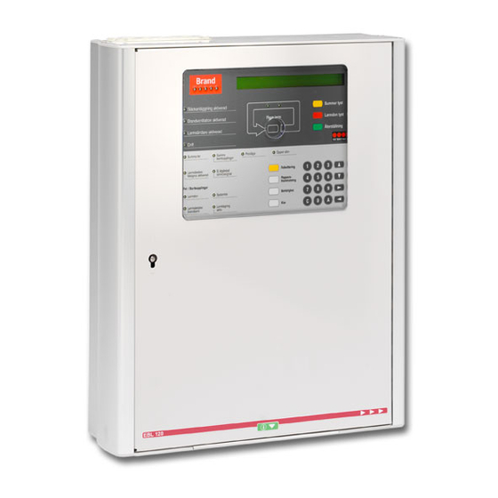
Figure 1. The EBL128 Control & Indicating Equipment (4550). Depending on country, convention, configuration, etc. the look, language and functions might vary. Figure 1 shows an EBL128 with English front. The metal housing consists of a wall mounted chassis on which a removable skin, incl. the door, is attached. This makes the installation and service very easy. - Page 18 Fire Brigade Panel (FBP) and the Control Panel (CP). Figure 2. The EBL128 front. The look might vary depending on the country (language), configuration, etc. (e.g. English texts as in the figure).
-
Page 19: Com Loop
The CP also holds several system status LEDs. COM loop EBL128 has one COM loop (0), to which the loop units are connected. Connections to "J1:1-4" according to drawing 128-21. On the COM loop can theoretically 255 COM loop units be connected (i.e. address 1-255). -
Page 20: A Single Break (Cut-Off) On The Com Loop
> 12 V DC. There can be none, one or up to 64 Short Circuit Isolators connected on the COM loop. In case of short-circuit or a break (cut-off) on the COM loop, EBL128 will in order to localize it, do the following: ... -
Page 21: Several Breaks (Cut-Offs) On The Com Loop
Panasonic Eco Solutions Nordic AB MEW01622 Rev: - EBL128 Planning Instructions V2.0.x must be a single break (cut-off) on the COM loop. One fault will be generated and the following fault message will be shown: FAULT: Cut-off SCI nn <-> SCI nn nn = A, B, 00, 01, 02, 03 and up to 63 depending on if none, one or several isolators are used. -
Page 22: Short-Circuit On The Com Loop
. Connections to "J1:5-8" according to drawing 128-22. When the connections are finished, a calibration has to be performed . See also the EBL128 Operating Instructions chapter "Calibration of supervised outputs (menu H5/A1)". Each output has to be programmed (via EBLWin) regarding: ... -
Page 23: Programmable Relay Output (R0)
LED "Fault tx activated". This output can be disabled via "door open" or via menu H2/B10. This output can be tested via menu H1, see the EBL128 Operating Instructions. Programmable input (I0) Connections to "J1:9-10" according to drawing 128-22. -
Page 24: Dc Power Supply Outputs
Panasonic Eco Solutions Nordic AB MEW01622 Rev: - EBL128 Planning Instructions V2.0.x Logic, i.e. Normally open (high resistance, 3K3, when supervised) or Normally closed (low resistance, 680R, when supervised) Additional information depending on selected type See also chapter "Programmable inputs", page 63. -
Page 25: Internal Power Supply
Panasonic Eco Solutions Nordic AB MEW01622 Rev: - EBL128 Planning Instructions V2.0.x Batteries (2 x 12 V, 18 Ah), 24 V (Two tab terminals, 6.35x0.8 mm, BATT + / BATT -) Connections to "J2:1-5" according to drawing 128-24. 4.10... -
Page 26: Expansion Boards 458X
EBL128 Planning Instructions V2.0.x Expansion boards 458x Inside EBL128, in an optional expansion board holder 4551, can up to four optional expansion boards of types 4580, 4581 and 4583 be mounted. A supplied ribbon cable is used for the connection of the expansion board(s) to the main board. -
Page 27: Expansion Board Address Setting
Panasonic Eco Solutions Nordic AB MEW01622 Rev: - EBL128 Planning Instructions V2.0.x Expansion board address setting The expansion board address is set via jumpers on the expansion board respectively. Board 4580, 4581 and 4583 4582 address Open Open Open Open... -
Page 28: Type Of Zone Line Input
This generates a fault condition in EBL128. From this state any other state can be reached / activated except the open circuit state. -
Page 29: Relays Expansion Board 4581
Open circuit current limit is passed, indicating no or too low zone line current consumption, i.e. the end-of-line device is not detected, which generates a fault condition in EBL128. From this state any other state can be reached / activated. 5.2.2.6... - Page 30 One to five 33K resistors can be connected. When the connections are finished, a calibration has to be performed. Calibration value has to be in the range 4K7-50K. See also the EBL128 Operating Instructions chapter "Calibration of supervised outputs (menu H5/A1)".
-
Page 31: I/O Matrix Board 4582
Up to four 4582 boards can be used and up to eight if no expansion boards of type 4580, 4581 or 4583 are used. The I/O Matrix board makes it possible for any retailer to manufacture and connect three different types of "Application boards" to EBL128 via the COM loop. EBL512 NOTE! C.i.e. -
Page 32: Generic
MEW01622 Rev: - EBL128 Planning Instructions V2.0.x In EBL128 can totally up to 200 outputs be used, including all kinds of outputs. For more information (e.g. application board type selected via jumpers JP4-JP5), see the I/O Matrix board 4582, Technical description MEW00914. -
Page 33: Zone Control
Panasonic Eco Solutions Nordic AB MEW01622 Rev: - EBL128 Planning Instructions V2.0.x Fan control panel 4593 has two Fan control application boards 4594 and two Fan control fronts. See Technical Description Fan control panel 4593 (MEW01245). Each Fan (0-3) (i.e. each Fan control) has to be added and programmed via EBLWin. -
Page 34: Peripheral Devices
COM loop. Addressable sounders (alarm devices) are connected directly on the COM loop. Input devices as key cabinet, timer, external fault, etc. are connected to programmable inputs, i.e. to input (I0) in EBL128 and/or to input units connected to the COM loop. Display units are connected to the RS485 interface in EBL128. - Page 35 Each COM loop unit has to have a unique technical address (001- 255). This address and the mode are set with an Address Setting Tool 3314 / 4414. For EBL128 is the NORMAL mode used (default) if nothing else is stated. To set the detectors 440x in Advanced mode...
-
Page 36: Input Units
Panasonic Eco Solutions Nordic AB MEW01622 Rev: - EBL128 Planning Instructions V2.0.x 6.1.1 Input units Each COM loop input unit is added and programmed via EBLWin. Depending on type of unit, regarding: Technical address (001-255) Name (normally not changed) ... - Page 37 The Address setting tool is also used for mode setting: NORMAL mode: Used for 4313 in EBL128. 2330 mode: Not used in EBL128. 2312 mode: Not used in EBL128.
- Page 38 The Address setting tool is also used for mode setting. NORMAL mode: Flashing or not flashing LED (see Product leaflet MEW00098) is set via EBLWin. 2330 mode: Not used in EBL128. 2312 mode: Not used in EBL128. 4439 Enclosed Addressable Manual Call Point with isolator.
- Page 39 B S (69-85°C), min./typical/max. ambient temp. -20/+40/+65°C 2330 mode: 3309 is in this mode like addressable heat detector 2340. 2312 mode: Not used in EBL128. 4300 Analog multi detector. Replaced with 4400, see below. A smoke detector and a heat detector within one housing.
- Page 40 Panasonic Eco Solutions Nordic AB MEW01622 Rev: - EBL128 Planning Instructions V2.0.x OR-functionality: Either the heat detector or the smoke detector will activate fire alarm. This alternative is recommended in most cases. Decision algorithm: Fire alarm will be activated if: temperature (°C) + adjusted smoke value...
- Page 41 2330 mode: 4300 in this mode (+ base 3312) works like the ionization smoke detectors 2316 / 2317 (+ base 2330). 2312 mode: Not used in EBL128. 4400 Analog multi detector. Replaces 4300, see above. 4400 is a smoke detector and a heat detector in one housing. Scattered light (i.e.
- Page 42 2330 mode: 4400 in this mode will work as a 2330 + 2316/17. 2312 mode: Not used in system EBL128. 4301 Analog photo electric smoke detector. Replaced with 4401, see below. Scattered light (i.e. reflection of infrared light) is used to detect smoke.
- Page 43 Panasonic Eco Solutions Nordic AB MEW01622 Rev: - EBL128 Planning Instructions V2.0.x channel. 4401 has a green polling LED. Via EBLWin is set if the green polling LED shall blink when the detector is polled or never blink. Note, the LED will not be blinking if the detector is in Test mode.
- Page 44 Panasonic Eco Solutions Nordic AB MEW01622 Rev: - EBL128 Planning Instructions V2.0.x 4452 Photoelectric smoke detector. Replaces 4352, see above. Like 4352 but 4452 has a little different design than the 4352 detector (see 4401 above) and the smoke chamber net has even smaller holes.
- Page 45 Panasonic Eco Solutions Nordic AB MEW01622 Rev: - EBL128 Planning Instructions V2.0.x 6.1.1.6 Accessories 3314 Address setting tool. Replaced with 4414, see below. Is used to write or read the COM loop units' technical address (001- 255). It is also used to write or read the mode, NORMAL or 2330 (see the unit respectively).
-
Page 46: Addressable I/O Units
Panasonic Eco Solutions Nordic AB MEW01622 Rev: - EBL128 Planning Instructions V2.0.x 3390 Label holder. To be mounted on the analog base 3312 Intended for a label with "zone-address", "technical address", etc. to be read also when the detector is plugged in its base. 100 label holders per packet. - Page 47 Panasonic Eco Solutions Nordic AB MEW01622 Rev: - EBL128 Planning Instructions V2.0.x NORMAL mode: Used for 3361 in EBL128. 2330 mode: Not used in EBL128. 2312 mode: Not used in EBL128. NOTE! See also chapter "Limitations", page 174. 3364 Addressable 2 voltage outputs unit.
-
Page 48: Alarm Devices (Addressable)
Panasonic Eco Solutions Nordic AB MEW01622 Rev: - EBL128 Planning Instructions V2.0.x NORMAL mode: Used for 3364 in EBL128. 2330 mode: Not used in EBL128. 2312 mode: Not used in EBL128. NOTE! See also chapter "Limitations", page 174. 6.1.3 Alarm devices (addressable) 3377 Addressable siren. - Page 49 COM loop address set via the Address setting tool.) The Address setting tool is also used for mode setting: NORMAL mode: Used for 3379 in system EBL128. 2330 mode: Not used in system EBL128. 2312 mode: Not used in system EBL128.
-
Page 50: Short Circuit Isolators (Addressable)
(Sequence Number 00-01-02-03- 04-05-06-07-08-09-10-11-12-13-14-15 - - up to 63) in the COM loop's A-direction. NOTE! EBL128 has one built-in isolator in the- A direction (no. "A") and one in the B-direction (no. "B"). The units 4433, 4439 and 4477 have a built-in isolator that don't occupy any COM loop address and the isolator’s Sequence Number is set in the... - Page 51 01 and the old no. 01 has to be changed to no. 02 and so on. Short circuit / cut-off (break) on the COM loop See chapter "COM loop", page 17. See also chapter "Fault messages" in the EBL128 Operating Instructions.
-
Page 52: Units For Hazardous (Ex) Areas
Panasonic Eco Solutions Nordic AB MEW01622 Rev: - EBL128 Planning Instructions V2.0.x 6.1.5 Units for Hazardous (Ex) areas In hazardous (Ex) areas, Intrinsically Safe (IS) and approved products are required. The IS alarm points are connected to an interface outside the Ex area. - Page 53 Panasonic Eco Solutions Nordic AB MEW01622 Rev: - EBL128 Planning Instructions V2.0.x 6.1.5.1 Intrinsically Safe (IS) mounting bases YBN-R / 4 IS Intrinsically Safe mounting base (2812). In the base can be plugged a conventional intrinsically safe smoke (2810) or heat (2811) detector. The base has terminals for the zone line (in/out) and for an ext.
-
Page 54: Other Com Loop Units
6.1.6 Other COM loop units 3366 External power supply. Conforms to EN54-4. The unit is connected to a COM loop, i.e. it is monitored from EBL128 and e.g. loss of the main power source will generate a fault in EBL128. -
Page 55: Units Connected To The Rs485 Interface
Address and S/W mode settings The display and the push buttons (in the unit respectively) are used to set the address, which also can be changed via EBL128. The S/W mode shall be set to xxxx – 1587 (xxxx = type number). See the Technical Description for the unit respectively. -
Page 56: Alert Annunciation Units
EBL128 Planning Instructions V2.0.x selected fire alarms can be stored in the unit and will in such a case be shown, instead of the texts sent from EBL128 for these alarms. These text messages will be downloaded to the unit via EBL128. - Page 57 EBL128. Furthermore, at least 617 texts can for selected fire alarms be stored in the unit and will in such a case be shown, instead of the texts sent out from EBL128 for these alarms. These text messages will be downloaded to the unit via EBL128.
-
Page 58: External Presentation Units
It can be silenced. Any disablement in the system will be presented as "General disablement in system". A built-in buzzer will sound like in EBL128. The buzzer can be silenced but the alarm devices in the installation cannot be silenced via this unit. -
Page 59: Units Connected To The Rs232 Interface J5
DIN 14661. The front's designation texts are in German. Serial RS485 interface for IHD protocol. The unit is power supplied from EBL128 (or an ext. power supply). Up to 1200 m cable can be used. NOTE! Switch 1 on the DIP switch shall be set to "on". -
Page 60: Units Connected To The Rs232 Interface J3
Units connected to the RS232 interface J3 J3 is a 9 ways female "D" connector. This interface is used only for connection of a PC with the PC program EBLWin to an EBL128 c.i.e. EBLWin is used for download / backup of the Site Specific Data (SSD), new software (firmware) download, the Web-server configuration, etc. -
Page 61: Other Units
Alert Annunciation Controller (AAC). This unit has no display, i.e. it has to be mounted close to EBL128 (or an ext. FBP) where the fire alarms will be presented. The compact size enclosure (HxWxD, 145 x 220 x 50 mm) is made of grey high impact ABS. -
Page 62: Alarm Devices (Sounders, Etc.)
Regarding addressable alarm devices, see page 47. In the Panasonic product range are no conventional (not addressable) alarm devices, intended for a supervised (monitored) voltage output (e.g. S0 or S1 in EBL128). Connections of alarm devices according to drawing 128-22. For addressable sounders, see page 47. -
Page 63: Programmable Inputs
Rev: - EBL128 Planning Instructions V2.0.x Programmable inputs EBL128 has one programmable input (I0). In EBL128 can also be mounted the Inputs and Outputs expansion board 4583, with five programmable inputs (Input 0-4) that can be supervised or not supervised. See chapter "Expansion boards 458x", page 24. -
Page 64: Control Unit Input I0 & Inputs And Outputs Exp. Board 4583, Input 0-4
Short-circuit 7.1.2.1 Input line fault If open circuit (cut-off) or short-circuit is detected on a supervised input, a fault will be generated in EBL128 and the following fault message will be displayed: FAULT: Programmable input alternatively FAULT: Programmable input x exp. board x... -
Page 65: 3361 Unit Inputs In0 / Z & In1
Panasonic Eco Solutions Nordic AB MEW01622 Rev: - EBL128 Planning Instructions V2.0.x 3361 unit Inputs In0 / Z & In1 Connections, see drawing 128-26. NOTE! The input In0 / Z can be used as a general input (In0) or as a monitored zone line input (Z) requiring an end-of-line capacitor (470 nF). -
Page 66: Input Programming
Panasonic Eco Solutions Nordic AB MEW01622 Rev: - EBL128 Planning Instructions V2.0.x Input programming Input programming is done via EBLWin. Each input has to have an individual Trigger condition ("Type") and Logic. Each input can be supervised or not supervised. - Page 67 10. Activated input will activate all programmable outputs of type "Alarm devices" steady (continuous). 11. Ext. fault will activate a fault in EBL128. A user definable fault message ("text") with up to 40 characters will be shown. 12. External clock, timer, key switch, switch, etc. can disable / re- enable alarm points.
- Page 68 See also chapter "Interlocking function", page 88. 23. Fault output "Loss of the battery charger to external power supply equipment" will activate a fault in EBL128. It will have the same time delay, as set for the "Loss of main power source" fault for EBL128.
-
Page 69: Logic
Panasonic Eco Solutions Nordic AB MEW01622 Rev: - EBL128 Planning Instructions V2.0.x 26. Used for the "outside switch" (i.e. the New Zealand FB Silence switch). 27. Pre-warning, e.g. from a High Sensitive Smoke Detector's pre- warning output. Zone no. and Address set to the same as the corresponding fire alarm (from the same detector). -
Page 70: Programmable Outputs
Rev: - EBL128 Planning Instructions V2.0.x Programmable outputs EBL128 has two programmable voltage outputs (S0 and S1) and one programmable relay output (R0). 8 relay outputs expansion board 4581 can be mounted in EBL128. Input and Output expansion board 4583 with three programmable outputs (Output 0-2) can be mounted in EBL128. -
Page 71: Control Unit Outputs S0 - S1
(not monitored). A normally high output can not be supervised. Supervised outputs have to be calibrated via menu H5/A1, see the EBL128 Operating Instructions. 1-5 supervision resistors 33K can be used. The calibrated value has to be in the range 4K7-50K. A fault will be generated for a value outside this range. -
Page 72: Control Unit Output R0
Connections and more information, see drawing 128-22. See also chapter "Programmable voltage outputs (S0-S1)", page 20. Control unit output R0 EBL128 has one programmable relay output: Relay output, NO or NC contacts programmable. As default R0 is set to type "Routing equipment" (Fire brigade tx), Steady (cont.), normally open and trigger condition "Fire brigade tx". -
Page 73: The 3364 Unit Outputs Vo0, Vo1 & Vo2
Panasonic Eco Solutions Nordic AB MEW01622 Rev: - EBL128 Planning Instructions V2.0.x Relay contacts: max. 2 A @ 30 V DC / 125 V AC (60W). Connections and more information, see drawings 128-21 & -26. The 3364 unit outputs VO0, VO1 & VO2... -
Page 74: Output Programming
Panasonic Eco Solutions Nordic AB MEW01622 Rev: - EBL128 Planning Instructions V2.0.x Output programming Output programming is done via EBLWin. See the EBLWin dialog box respectively. 10.1 Type The following output types are available (see also comments below): 0. Control 1. -
Page 75: Logic
Panasonic Eco Solutions Nordic AB MEW01622 Rev: - EBL128 Planning Instructions V2.0.x 10.2 Logic The logic is set in the EBLWin dialog box "Voltage or Relay Output". (•) Normally open / low Normally open relay contacts / normally low voltage output. - Page 76 Panasonic Eco Solutions Nordic AB MEW01622 Rev: - EBL128 Planning Instructions V2.0.x Figure 13. Delay time, Pulse length, Pulse off and/or De- Activation, have to be set for the "Signal period" respectively. For types 1 & 4 the x and y times must be equal and max. 5.6s.
- Page 77 Panasonic Eco Solutions Nordic AB MEW01622 Rev: - EBL128 Planning Instructions V2.0.x In EBL128 COM loop units Output S0-S1 4581 4583 I/O unit Unit Siren, 4582 Inter S/B & Type 3361 3364 board locking board board Beacon & Light ind.
-
Page 78: Control Expression
Panasonic Eco Solutions Nordic AB MEW01622 Rev: - EBL128 Planning Instructions V2.0.x 10.5 Control expression Each programmable output has to be given a control expression. It is created by so called Boolean algebra. Trigger conditions (see "Available functions"), logical "Operators"... - Page 79 Panasonic Eco Solutions Nordic AB MEW01622 Rev: - EBL128 Planning Instructions V2.0.x 10.5.1.1 Alarm Fire Alarm Zone (+Zone no.) Fire Alarm Zone Address (+Zone no.+Address) General Fire Alarm Consecutive Fire Alarm (sequence) (+start Zone no. and address +stop Zone no. and address +Quantity) Pre Warning Zone (+Zone no.)
- Page 80 Comments to the trigger conditions (functions): Alarm Fire alarm. For more information regarding fire alarm, see EBL128 Operating Instructions MEW01623. Output is activated when the specified Zone is in alarm. See 1. Output is activated when the specified alarm point is in alarm.
- Page 81 See 5. See also 4 above regarding "Quantity". Heavy smoke / heat alarm. For more information regarding heavy smoke / heat alarm, see EBL128 Operating Instructions MEW01623. Output is activated when the specified Zone is over the heavy smoke / heat level.
- Page 82 Panasonic Eco Solutions Nordic AB MEW01622 Rev: - EBL128 Planning Instructions V2.0.x Output activated when interlocking inputs, in the specified range, are activated (from interlocking area no. / point to interlocking area no. / point). See also 4 above regarding "Quantity".
- Page 83 Output activated when Alert annunciation alarm is activated (by any alarm point set to activate this function). For more information, see EBL128 Operating Instructions MEW01623. Output activated when Alert annunciation alarm is activated (by any alarm point set to activate this function) and acknowledged.
-
Page 84: Logical Operators
Panasonic Eco Solutions Nordic AB MEW01622 Rev: - EBL128 Planning Instructions V2.0.x Output activated when input trigger condition "Extinguishing system fault" is true. Output activated when input trigger condition "Extinguishing system released" is true. Output activated when input trigger condition "Activated key cabinet"... - Page 85 Panasonic Eco Solutions Nordic AB MEW01622 Rev: - EBL128 Planning Instructions V2.0.x 10.6.1.2 a OR b OR c=y y is true if at least one of the conditions a, b, c is true, i.e. a=1 or b=1 or c=1 makes y=1.
- Page 86 Panasonic Eco Solutions Nordic AB MEW01622 Rev: - EBL128 Planning Instructions V2.0.x 10.6.1.4 Parentheses Changes priority order. a OR NOT (b AND c)=y (This is same as the previous but parentheses are added, which makes a differance.) This is shown in the following table: 10.6.1.5...
- Page 87 General Control disabled AND NOT Door Open Explanation: Controls disabled via menu H2/B7 will activate the output R0 when the door in EBL128 is not open (i.e. when it is closed). Example 3 Output: Voltage output VO0 Control expression: Fire Alarm Zone (23) AND Fire Alarm Zone...
-
Page 88: Interlocking Function
Panasonic Eco Solutions Nordic AB MEW01622 Rev: - EBL128 Planning Instructions V2.0.x Interlocking function The interlocking function is used to verify that an output really is activated, i.e. by "combining" an output with an input (feed-back from the equipment controlled by the corresponding interlocking output). - Page 89 EBLWin", page 114. Buzzer checked = activated interlocking input will turn on the EBL128 buzzer (0.8 / 0.8 sec.) . The buzzer can be silenced. It will be automatically turned on again, if a new interlocking input is activated.
-
Page 90: Interlocking Indications
Date: MM-DD Time: HH:MM 11.2 Interlocking indications One or more activated Interlocking Combinations (interlocking output and/or input) are indicated in the display in EBL128 Interlocking input/output activated See menu H9/C1 Disabled interlocking output is indicated by the LED "Disablements". 11.3... -
Page 91: Reset Interlocking Output (H9/C3)
Panasonic Eco Solutions Nordic AB MEW01622 Rev: - EBL128 Planning Instructions V2.0.x control expression. Reset has to be performed via menu H9/C3. 11.3.3 Reset interlocking output (H9/C3) Activated interlocking outputs are listed here. Use "↑" "↓" to scroll between the "Interlocking Combinations" (Area / Point). -
Page 92: Fire Door Closing Function
See also chapter "Interlocking function", page 88. It is recommended but in the DBI (Danish) convention, must only EBL128 outputs R0 and S0-S1 as well as the COM loop unit 3364 be used and "Type of output" has to be "Control neutral". -
Page 93: Functions / Services / Features
13.2 Week average sensor value Each hour, one sensor value is stored in a special memory (in EBL128) and each week, these stored sensor values are used for a "week average sensor value" calculation. This is done for each analog smoke detector individually. In Figure 17 the (digital) week average sensor values (during a certain time) are represented by the graph "... -
Page 94: Decision Value
Service level (D). "Sensor Information" is available via menu H4/U4. Via EBLWin and a PC connected to EBL128 you can also get continuous "Sensor Information" for one or several detectors. Also via the Web-server II 1598 you can get "Sensor Information" for one or several analog detectors on a COM loop. -
Page 95: Alarm Algorithm / Alternative Alarm Algorithm
"Pre-warning", "Fire Alarm" and "Heavy Smoke Alarm" can activate programmable outputs respectively, see chapter "Control expression", page 78. See also EBL128 Operating Instructions MEW01623. 13.4.1 Alarm algorithm / Alternative alarm algorithm In order to reduce the nuisance alarms and ensure that the real fire alarms will be activated, six different alarm algorithms are available. -
Page 96: Filtering Algorithm
Panasonic Eco Solutions Nordic AB MEW01622 Rev: - EBL128 Planning Instructions V2.0.x 13.4.2 Filtering algorithm In order to secure a fast detection of real fire alarms and to reduce nuisance (false) alarms to a minimum, a filtering algorithm is used. - Page 97 In this example, alarm algorithm "N-15" is selected, i.e. normal detection time 15 sec. and normal sensitivity 3% (30). X = 5. The detector polling time t ≈ 2.56 sec. (In system EBL128 the detector polling time t ≈ 7 seconds and the step value "X" is according to Figure 18 –...
-
Page 98: Smouldering Smoke Algorithm
Panasonic Eco Solutions Nordic AB MEW01622 Rev: - EBL128 Planning Instructions V2.0.x 3. The decision value has here reached the pre-warning level and pre-warning is activated. 4. The decision value is here below the pre-warning level and the pre-warning is automatically reset. -
Page 99: Performance Factor
Panasonic Eco Solutions Nordic AB MEW01622 Rev: - EBL128 Planning Instructions V2.0.x Figure 20. An example of the smouldering smoke algorithm for an Analog smoke detector 4301. Explanations to the figure: In this example, the week average sensor value and the decision value are "10"... -
Page 100: Algorithms For Analog Heat Detectors
Panasonic Eco Solutions Nordic AB MEW01622 Rev: - EBL128 Planning Instructions V2.0.x values should be studied together. (E.g. one or two high sensor values will not result in a high performance factor.) The performance factor is calculated for each detector individually. -
Page 101: Class A2 S Algorithm
S/W and CPU. Every minute, each detector will receive a question from EBL128. If the self verification function has detected any fault it will be reported back to EBL128. A fault will be activated in EBL128 and the following fault message will be shown: FAULT: Detector xx-xx →... -
Page 102: Minimum / Maximum Sensor Values
430x / 440x in NORMAL mode is mounted, the minimum and maximum sensor values can be studied. The sensor values are continuously picked up and evaluated by EBL128 for each detector individually. Every value is checked if it is a new minimum or maximum value for that detector and if so, the value will be stored. -
Page 103: 2-Address (-Unit) Dependence
Panasonic Eco Solutions Nordic AB MEW01622 Rev: - EBL128 Planning Instructions V2.0.x 13.8.2 2-address (-unit) dependence Each analog detector, addressable multipurpose I/O unit (3361) monitored Input 0 (Z) and 8 zones expansion board (4580) input, can be programmed for 2-unit dependent fire alarm activation. (Heat detectors should not and manual call points must not be 2-unit dependent). -
Page 104: Alarm Verification Facility
After 15 seconds the zone will be automatically reset and if the zone comes in "fire alarm state" again within 110 seconds, a fire alarm will be activated in EBL128, else nothing will happen until the next time the zone is in "fire alarm state"... -
Page 105: Alert Annunciation
Panasonic Eco Solutions Nordic AB MEW01622 Rev: - EBL128 Planning Instructions V2.0.x 13.11 Alert Annunciation In some installations the Alert Annunciation function can be used to avoid unwanted false alarms (nuisance alarms) to the fire brigade. A time channel can turn on/off this function. -
Page 106: Alarm Acknowledgement Facility (Aaf)
Panasonic Eco Solutions Nordic AB MEW01622 Rev: - EBL128 Planning Instructions V2.0.x The AA alarm has to be acknowledged within an acknowledge time and the AA alarm has to be reset within an investigation time, else the output(s) for routing equipment (fire brigade tx) will be activated. - Page 107 Panasonic Eco Solutions Nordic AB MEW01622 Rev: - EBL128 Planning Instructions V2.0.x COM loop Sounder Base 3378 Smoke detector (4300, 4301) AAFC PRESS TO ACKNOWLEDGE FALSE ALARM Non-latching switch Figure 22. Alarm Acknowledgement Facility units. Function (see also the flow chart in the following figure): - One of the detectors in an AAF zone reaches its fire alarm level.
- Page 108 Panasonic Eco Solutions Nordic AB MEW01622 Rev: - EBL128 Planning Instructions V2.0.x Quiscent state Any detector in alarm? Buzzer ON AP timer starts Detector LED ON AAFC LED ON AAFC button pressed? IP timer starts Buzzer OFF Count down Detector LED OFF...
-
Page 109: Quiet Alarm
Panasonic Eco Solutions Nordic AB MEW01622 Rev: - EBL128 Planning Instructions V2.0.x Annunciation function. Only Analog photo electric smoke detector 4301 / 4401 and Analog multi detector 4300 / 4400 can be used for AAF. If the Analog multi detector 4300 / 4400 is used, it must be programmed as type "Two addresses", so that only the "smoke part"... -
Page 110: Fire Alarm Type B
Panasonic Eco Solutions Nordic AB MEW01622 Rev: - EBL128 Planning Instructions V2.0.x than for a fire alarm type B. The alarm receiver can take different actions depending on if it is a fire alarm type A or B. 13.14.1 Fire alarm type B The output shall be programmed (via EBLWin) as type "Routing... -
Page 111: Disable Zone
Panasonic Eco Solutions Nordic AB MEW01622 Rev: - EBL128 Planning Instructions V2.0.x shall not be selected, see chapter "System properties, Page 2", page 136. NOTE! Enhanced Disablement is NOT valid when a time channel is used for disablements, only when menu H2/B1-B2 are used. -
Page 112: Disconnect / Re-Connect Com Loop
H1) or via menu H7. Up to 99 zones can be set in Test mode via menu H7 but only four zones via menu H1. For more information see the EBL128 Operating Instructions. The LED "Test mode" indicates one or more zones in Test mode. Zones in Test mode are also simultaneously shown in the EBL128 display. -
Page 113: Test Of Routing Equipment
Calibration of supervised outputs The supervised (monitored) voltage outputs have to be calibrated after the installation is finished. This is done in EBL128 via menu H5/A1. A value outside the calibration value range 4K7-50K and 470 nF to 5x470 nF respectively, will generate a fault as well as when the actual value differs from the calibrated value ±... -
Page 114: Fault Signal (Fault Condition)
"Text" field where the alarm text for the alarm point can be typed (or edited). This is the text that will be shown in the display in EBL128 when this alarm point has activated a fire alarm and as from version 2.0 it will also be shown in the fault message. - Page 115 "00" (i.e. ZZZ – 00). Only the texts have to be typed / edited in the "Text" column. NOTE! In system EBL128 is the highest possible zone number 099 since only two digits can be shown in the display. Text column Shows already programmed alarm point / zone texts.
-
Page 116: Downloading Texts To The Dus 1728 / 1735 / 1736 And Ext. Fbps 1826 / 1828
The "display units" have to be connected to EBL128 and the address and mode have to be set in the "display units". The texts will then be downloaded at the same time as the EBL128 site specific data (SSD) is downloaded via EBLWin. Alt. via the DU pop-up menu in EBLWin. -
Page 117: Daylight Saving Time
Panasonic Eco Solutions Nordic AB MEW01622 Rev: - EBL128 Planning Instructions V2.0.x 13.23.1 Daylight saving time The time is automatically changed when the Daylight saving time period starts and stops respectively. This is depending on which convention that is used. -
Page 118: Event Log
Panasonic Eco Solutions Nordic AB MEW01622 Rev: - EBL128 Planning Instructions V2.0.x normally closed contact. When the input is "activated" the time channel (N) is ON. NOTE! Only one input per time channel can be used. 13.26 Event log The event log is divided into three types, i.e. Alarm, Interlocking and General. - Page 119 Panasonic Eco Solutions Nordic AB MEW01622 Rev: - EBL128 Planning Instructions V2.0.x Evacuate in progress The sounders will remain turned ON until they are turned OFF by pressing the soft key "Evacuate off" (P7). NOTE 1! The alarm devices (sounders) will always be activated steady (sound continuously) irrespective of the fact that the outputs can be set to anything else for fire alarm (e.g.
-
Page 120: Special New Zealand Functions
Panasonic Eco Solutions Nordic AB MEW01622 Rev: - EBL128 Planning Instructions V2.0.x Special New Zealand functions NOTE! The functions in this chapter are valid for the New Zealand convention only. 14.1 Alarm devices 14.1.1 Silence alarm devices (inside switch) On the c.i.e. front, the button "Silence alarm devices" (see Operating Instructions, button "P3") is called the "inside switch"... -
Page 121: Battery Faults
Panasonic Eco Solutions Nordic AB MEW01622 Rev: - EBL128 Planning Instructions V2.0.x The outside switch is turned OFF (i.e. from activated to not activated state). The c.i.e. built-in buzzer is re-enabled. The fault " FAULT: FB Silence switch active"... -
Page 122: Watchdog Reset
Panasonic Eco Solutions Nordic AB MEW01622 Rev: - EBL128 Planning Instructions V2.0.x The battery charging is turned off 60 minutes every 24 hour. Battery voltage is checked during this 60 minutes period. Battery voltage < 24.4 V generates a fault. -
Page 123: Advanced Mode
Panasonic Eco Solutions Nordic AB MEW01622 Rev: - EBL128 Planning Instructions V2.0.x Advanced mode The latest generation of detectors are the following: Conventional photoelectric smoke detector 4452 Analog photoelectric smoke detector 4401 Analog multi detector 4400 NOTE! NOTE! NOTE! NOTE! NOTE! NOTE! NOTE! The analog detectors 4401 and 4400 can via the address setting tool 4414 be set in different modes. -
Page 124: Pulse Up - Down Counter
Panasonic Eco Solutions Nordic AB MEW01622 Rev: - EBL128 Planning Instructions V2.0.x extended in order to reduce false (nuisance) alarms. A learning function will after a learning period adapt an Alarm algorithm suitable for the smoke and temperature conditions in the area where the detector is located. -
Page 125: Fire Judgement
Panasonic Eco Solutions Nordic AB MEW01622 Rev: - EBL128 Planning Instructions V2.0.x When the temperature rise deltaT (°C/168sec.) > the alarm threshold level, "3" is added to the counter every second. When T or deltaT < the alarm threshold level, "2" is subtracted from the counter every second. -
Page 126: Alarm Delay Time
Panasonic Eco Solutions Nordic AB MEW01622 Rev: - EBL128 Planning Instructions V2.0.x 15.4 Alarm delay time The alarm delay time will be different for the different type of detectors depending on the cause of alarm, Area alarm algorithm and the values before / after the fire alarm threshold level was exceeded. -
Page 127: Learning Function / Learning Period
Panasonic Eco Solutions Nordic AB MEW01622 Rev: - EBL128 Planning Instructions V2.0.x 15.5 Learning function / Learning period Detectors 4400 and 4401 can use a Learning function, i.e. Depending on the local temperature changes and the local occurrence of smoke... -
Page 128: Analog Data Output
Panasonic Eco Solutions Nordic AB MEW01622 Rev: - EBL128 Planning Instructions V2.0.x In the example, the Smoke - Steam area Alarm algorithm will be changed back to the Normal area Alarm algorithm after the 36h period no. 3, since at that time there are left only two 36h periods with check-marks in this learning period. -
Page 129: Sensitivity Compensation
Panasonic Eco Solutions Nordic AB MEW01622 Rev: - EBL128 Planning Instructions V2.0.x 4452: This detector has no analog output. 4400: This detector has a smoke obscuration value output, a temperature value output, actual area alarm algorithm output and a CCF (see below) output to the c.i.e. -
Page 130: Address Setting Check
Panasonic Eco Solutions Nordic AB MEW01622 Rev: - EBL128 Planning Instructions V2.0.x 15.9 Address setting check The red indication LEDs in the detectors 4401 and 4400 will in all modes be blinking every second when the detector is powered and the COM loop address is not set with the Address setting tool 3314 / 4414, i.e. -
Page 131: Control Unit Properties
Opens when you add a control unit or via the "Control unit" pop-up menu (Properties...) 16.1.1 General Information Control unit number: An EBL128 control unit has to have no. 0. No other number is allowed. Name: Normally not changed but can be changed when required. 16.1.2 Configuration Not valid for EBL128. -
Page 132: Eblwin Control Unit Pop-Up Menu
Panasonic Eco Solutions Nordic AB MEW01622 Rev: - EBL128 Planning Instructions V2.0.x 16.2 EBLWin Control unit pop-up menu Some commands might be disabled since you have to connect and log on to the control unit to be able to select / use them. -
Page 133: Restart
Panasonic Eco Solutions Nordic AB MEW01622 Rev: - EBL128 Planning Instructions V2.0.x 16.2.4 Restart You can restart control unit via this menu command. 16.2.5 Delete The selected control unit can be deleted. 16.2.6 Properties See beginning of this chapter – Control unit properties dialog box. -
Page 134: System Properties (Settings)
Panasonic Eco Solutions Nordic AB MEW01622 Rev: - EBL128 Planning Instructions V2.0.x System properties (settings) Figure 25. The EBLWin "System properties" dialog box, Page 1 and Page 2. NOTE! Default settings in EBLWin might vary depending on convention. 17.1 System properties dialog box Opens via the "System"... - Page 135 Panasonic Eco Solutions Nordic AB MEW01622 Rev: - EBL128 Planning Instructions V2.0.x 17.1.3.2 Alarm Acknowledgement Facility Used in conjunction with the AAF Control that is available on the Australian market only. See also chapter "Alarm Acknowledgement Facility (AAF)", page 106.
-
Page 136: System Properties, Page 2
Panasonic Eco Solutions Nordic AB MEW01622 Rev: - EBL128 Planning Instructions V2.0.x 17.1.3.5 Alarm delay time (seconds) Valid for the detectors and zone line inputs with this option selected via EBLWin 30 is default. 0-255 seconds is possible. Note, this delay time starts when the fire alarm normally should have been activated. - Page 137 Panasonic Eco Solutions Nordic AB MEW01622 Rev: - EBL128 Planning Instructions V2.0.x Enhanced disablements: Disabled alarm point will not activate pre-warning, fire alarm or fault. Checkbox not marked = Disabled alarm point will not activate pre-warning or fire alarm. Fault can still be activated.
-
Page 138: Eblwin Menus
Panasonic Eco Solutions Nordic AB MEW01622 Rev: - EBL128 Planning Instructions V2.0.x EBLWin menus 18.1 The File menu 18.1.1 To open a new installation. The type of system has to be selected. System EBL512 G3 System EBL128 18.1.2 Open To open an installation via a standard Windows dialog box "Open". -
Page 139: Exit
Panasonic Eco Solutions Nordic AB MEW01622 Rev: - EBL128 Planning Instructions V2.0.x For the Label holder (3390) can a MARKO sheet be used, i.e. Labels for 3390 (3391) 10 sheets à 132 labels. 18.1.7 Exit To exit / close EBLWin. -
Page 140: Selected Loop
Panasonic Eco Solutions Nordic AB MEW01622 Rev: - EBL128 Planning Instructions V2.0.x There is a button to open a list of: - fire alarms (selected or all can be reset) - faults (selected or all can be acknowledged) - disablements (selected or all can be re-enabled) -
Page 141: External Faults
Panasonic Eco Solutions Nordic AB MEW01622 Rev: - EBL128 Planning Instructions V2.0.x This is a list, for the whole system, showing all interlocking combinations and their properties. The list can be sorted by clicking the column header respectively. Double click an interlocking combination row to open its dialog box. -
Page 142: The System Menu
Panasonic Eco Solutions Nordic AB MEW01622 Rev: - EBL128 Planning Instructions V2.0.x This is a list, for the whole system, showing all external time channels and their properties. The list can be sorted by clicking the column header respectively. Double click an external time channel row to open its dialog box. - Page 143 Panasonic Eco Solutions Nordic AB MEW01622 Rev: - EBL128 Planning Instructions V2.0.x The properties for each Time channel (2-14) and each Day of the week (Monday to Sunday + National Holiday) have to be set for the channel respectively. Figure 26. Left: The "Time channel 2" dialog box without any programming done.
-
Page 144: Alarm Algorithms
Panasonic Eco Solutions Nordic AB MEW01622 Rev: - EBL128 Planning Instructions V2.0.x Tuesday: Programmed the same way as the Monday. Wednesday: Programmed the same way as the Monday. Thursday: Programmed the same way as the Monday. Friday: Programmed the same way as the Monday. - Page 145 Name: Name of the algorithm (e.g. N-15, Class A1 & Decision). Normally not changed. Abbrevation: The algorithm abbreviation (< six characters) as shown in the EBL128 display, menu H4/U4 (e.g. N-15, A1 & Des). Normally not changed. 18.3.3.1 Parameters for smoke algorithms Valid for the detectors 4300 / 4400 and 4301 / 4401.
-
Page 146: Output Signal Periods
Panasonic Eco Solutions Nordic AB MEW01622 Rev: - EBL128 Planning Instructions V2.0.x In addition, a special password is required to change the parameters for fire alarm. 18.3.3.2 Parameters for heat algorithms Valid for the detectors 3308 / 3309 and the multi detectors 4300 / 4400. - Page 147 Panasonic Eco Solutions Nordic AB MEW01622 Rev: - EBL128 Planning Instructions V2.0.x In the list (to the left), Steady (continuously) and Intermittent 0.8 / 0.8 s are already defined since these alternatives are often used. It is however, possible to define them to something else.
-
Page 148: National Holidays
Panasonic Eco Solutions Nordic AB MEW01622 Rev: - EBL128 Planning Instructions V2.0.x 18.3.5 National holidays Up to twenty national holidays can be set for the whole system. National holidays can be added one by one, i.e. by selecting a date in the calendar (up to the right) and click with the left mouse button. -
Page 149: Two Zone Dependence
Panasonic Eco Solutions Nordic AB MEW01622 Rev: - EBL128 Planning Instructions V2.0.x 18.3.6 Two zone dependence See also chapter "2-zone dependence", page 102. Default for all zones is no two zone dependence. NOTE! Normally, only conventional zones (i.e. zone line inputs with conventional detectors) should be used for two-zone dependence. -
Page 150: User Data
User level Service personnel gives access to the menus H1 - H10. (Level 3A according to EN54-2.) For more information regarding user names, passwords, user levels, logon to a control unit, etc. see EBL128 Operating Instructions, MEW01623. 18.4 The Tools menu The EBLWin menu "Tools"... - Page 151 / information are the same in the control unit and EBLWin. Download SSD…: (When connected and logged on to an EBL128.) Opens a dialog box for download of SSD to the EBL128 control unit, the Web-server and connected "Display Units" (e.g. Ext. FBP).
-
Page 152: The Help Menu
Panasonic Eco Solutions Nordic AB MEW01622 Rev: - EBL128 Planning Instructions V2.0.x algorithm parameters can be changed. Convention will be possible to change in "Options…". Backup EBLWeb configuration: (When connected to a Web- server.) Opens a dialog box for backup ("upload") of the Web-server configuration to EBLWin. -
Page 153: Download Ssd
Download SSD The PC program EBLWin is used for creating the Site Specific Data (SSD) and to download it to the EBL128 control unit, the Web-server and/or connected Display Units 1728, 1735, 1736, 1826 & 1828. When the installation is ready, i.e. all units connected and the power is turned on, the SSD download can take place. -
Page 154: Auto Generate Loop
Panasonic Eco Solutions Nordic AB MEW01622 Rev: - EBL128 Planning Instructions V2.0.x shown, i.e. an indication where the break (cut-off) or short circuit is located. For all units, the address (1-255) and the type of unit will be reported to EBLWin. All differences compared to the installation (SSD) that is open in EBLWin will be listed and can be saved and/or printed out. -
Page 155: User Definable Text Messages Download
Panasonic Eco Solutions Nordic AB MEW01622 Rev: - EBL128 Planning Instructions V2.0.x 19.3 User definable text messages download Each alarm point, zone and zone line input can have a unique user definable alarm text programmed via EBLWin. When a fire alarm is activated (e.g. -
Page 156: Download Software (S/W)
Rev: - EBL128 Planning Instructions V2.0.x Download software (S/W) The latest EBL128 software (S/W) version is factory downloaded before the delivery. Due to continual development and improvement, different S/W versions can be found. The valid S/W version can be read in menu H4/U7 or via EBLWin. - Page 157 Panasonic Eco Solutions Nordic AB MEW01622 Rev: - EBL128 Planning Instructions V2.0.x 2. Set the Main board in "boot" mode, i.e. put the jumper onto the two pins marked "BOOT" (JP2) and then momentarily short the two solder pads marked "RESET" (JP1). The buzzer sounds continuously.
-
Page 158: Cable Types
COM loop cables Loop topology is used for highest safety, i.e. the cable connected in EBL128, returns back to EBL128. See drawing 128-21. In case of a single break on the loop the communication starts in both directions and a fault is generated (and a message is displayed). -
Page 159: Com Loop Cable Length
Panasonic Eco Solutions Nordic AB MEW01622 Rev: - EBL128 Planning Instructions V2.0.x COM loop cable length On the COM loop can theoretically up to 255 COM loop units be connected (i.e. address 1-255). The cable length and max. COM loop... - Page 160 Panasonic Eco Solutions Nordic AB MEW01622 Rev: - EBL128 Planning Instructions V2.0.x Maximum conductor resistance 120 160 200 240 280 320 Total COM loop unit current consumption Figure 30. Graphs showing the total conductor resistance in relation to the COM loop units' total current consumption. NOTE! The graphs start at "0 mA"...
- Page 161 Panasonic Eco Solutions Nordic AB MEW01622 Rev: - EBL128 Planning Instructions V2.0.x Maximum cable length Meter 2 x 1 mm (0.75 mm 24.5 ohm / km Total COM loop unit current consumption Figure 31. Graphs showing the cable length in relation to the COM loop units' total current consumption.
-
Page 162: Current Consumption
Panasonic Eco Solutions Nordic AB MEW01622 Rev: - EBL128 Planning Instructions V2.0.x Current consumption The different loop units have different current consumption. Note that some units have much higher current consumption in "active state" than in normal state. The tables below can be used: ... - Page 163 Panasonic Eco Solutions Nordic AB MEW01622 Rev: - EBL128 Planning Instructions V2.0.x COM loop units (input units, etc.) Normal state Alarm state (quiescent) (mA) (activated) (mA) Analog smoke detector 2300 / 2304 + analog base 2312 1.7 / 1.8 3.7 / 3.8...
- Page 164 Panasonic Eco Solutions Nordic AB MEW01622 Rev: - EBL128 Planning Instructions V2.0.x COM loop units (output units, etc.) Normal state Alarm state (quiescent) (mA) (activated) (mA) Addressable short circuit isolator 4370 Analog base with isolator 4313 Addressable multipurpose I/O unit 3361 max.
- Page 165 Panasonic Eco Solutions Nordic AB MEW01622 Rev: - EBL128 Planning Instructions V2.0.x Other units Normal state Alarm state (quiescent) (mA) (activated) (mA) Routing equipment (Fire brigade tx / Fault tx) Acc. to the producer Acc. to the producer External Presentation unit 1728...
- Page 166 Panasonic Eco Solutions Nordic AB MEW01622 Rev: - EBL128 Planning Instructions V2.0.x The following table is a help when calculating the cable length and/or the number of units. The table is based on the current consumption at the lowest power supply voltage allowed i.e. 21 V DC by battery back-up (no mains).
-
Page 167: Power Supply
Power Supply (rectifier), 230 V AC / 24 V DC ±1%, 1.8 A). Second power source By loss of 230 V AC, etc. EBL128 is powered by built-in back-up batteries, i.e. two Sealed Lead-Acid batteries, 12 V, 16-18 Ah. The batteries and the rectifier are connected to the Main board (4556), which also handles the charging of the batteries. -
Page 168: Battery Charging Functions
Rectifier 4557 to the Main board 4556 exceeds 1.8 A, i.e. the EBL128 current consumption exceeds 0.8 A. The battery charging will remain turned off as long as the EBL128 current consumption exceeds 0.75 A. It will generate a fault and the... -
Page 169: Current Consumption Calculations
I = the current consumption for all other equipment alarm state. The total EBL128 current consumption in Normal ( quiescent ) state: The total EBL128 current consumption in Alarm ( activated ) state: Comments regarding (I has to be < 0.7 A. -
Page 170: Main Power Source (Power Supply)
(theoretically) in a battery back-up time of 30 hours. Comments regarding (I has to be < 1.8 A. See Figure 32, page 167. Total EBL128 current consumption in relation to back-up time, see the table in chapter "Second power source (Battery)", page 170. 24.3 Main power source (Power Supply) The main power source is a Switching Power Supply (rectifier). -
Page 171: Form / Table Of Current Consumption
Panasonic Eco Solutions Nordic AB MEW01622 Rev: - EBL128 Planning Instructions V2.0.x NOTE! The values are calculated and give only a rough idea of the back-up time. 24.5 Form / Table of current consumption Some national regulations require different forms / tables regarding current consumption, to be filled in. -
Page 172: W Versions
Panasonic Eco Solutions Nordic AB MEW01622 Rev: - EBL128 Planning Instructions V2.0.x S/W versions Due to continual development and improvement, different S/W versions can be found. Different S/W versions can be found on different markets. The S/W versions listed below were valid when this document was written (the date of this document or date of revision). -
Page 173: Technical Data
Metal cabinet: Aluminium & light grey (NCS S 1500-N / PMS Cool Gray 2) Approvals EBL128 is fully compliant with the European standard EN54 parts 2 and 4 and the front is fully SS3654 compliant. The rated output voltage is 24 V DC ± 1% for the main power source (rectifier). -
Page 174: Limitations
Rev: - EBL128 Planning Instructions V2.0.x Limitations 27.1 C.i.e. Max. number of "items": Item Max. no. Fire alarms (presented in the EBL128 display as ZONE and/or ZONE- ADDRESS) Number of zones Faults External faults Technical warnings Short circuit isolators Loop units Trigger conditions (in all the control Approx. -
Page 175: National Regulations / Requirements
When planning a fire alarm installation, national regulations, customer demands, etc. have to be followed. EBL128 is very flexible with the many built-in functions & facilities in the S/W and the PC program EBLWin. When downloading the S/W and/or the SSD, different settings, conventions, languages, etc. -
Page 176: Drawings / Connection Diagrams
Panasonic Eco Solutions Nordic AB MEW01622 Rev: - EBL128 Planning Instructions V2.0.x Drawings / connection diagrams All dimensions quoted are approximate only and subject to change without notice, as are other technical features and data, resulting from continual development and improvement. -
Page 177: Revision History
Panasonic Eco Solutions Nordic AB MEW01622 Rev: - EBL128 Planning Instructions V2.0.x Revision history... - Page 178 This page has deliberately been left blank.
- Page 179 Panasonic Eco Solutions Nordic AB Jungmansgatan 12, SE-211 19 Malmö, Sweden Tel: +46 (0)40 697 70 00 • Fax: +46 (0)40 697 70 99 E-mail: [email protected] • Internet: http://pesn.panasonic.se...