EOS EmoTouch II + Steam Installation And Operating Manual
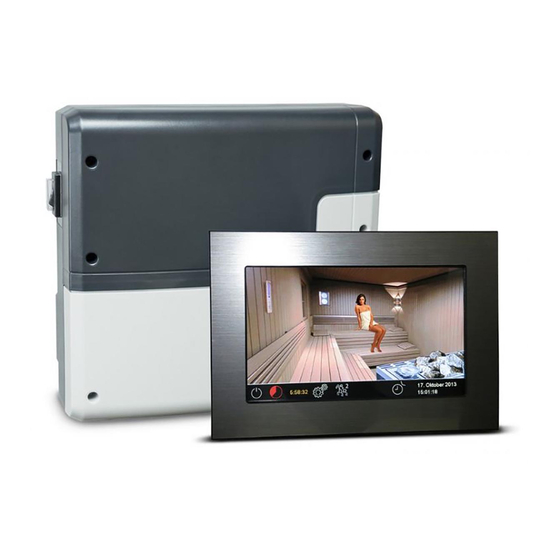
Steam bath control unit
Hide thumbs
Also See for EmoTouch II + Steam:
- Installation and operation instruction manual (43 pages) ,
- User manual and operating manual (30 pages)

Related Manuals for EOS EmoTouch II + Steam


Summary of Contents for EOS EmoTouch II + Steam
- Page 1 I N N O V A T I V E S A U N A T E C H N O L O G Y EmoTouch II + Steam Steam bath control unit Installation and operating manual Made in Germany Print no.
-
Page 2: Table Of Contents
English Content Scope of Delivery ..............................4 Accessories ................................4 Technical data ................................5 General information about the steam bath ....................6 General safety regulations ........................... 7 Installation ................................. 9 Main relay box .............................9-10 Display panel ..............................11 Temperature sensor ............................14 Electrical connection............................16 Connection of the steam generator .......................16 Connection of the lighting .........................17... -
Page 4: Scope Of Delivery
Delivery scope (Subject to change) Main relay box (2-part front cover), wall-mounted Control panel with 7“ touchscreen display (upper part of housing) - not for 945950- Lower part of housing (for installation of the control panel) - not for 945950- Dismantling tools for control panel (2x) -not for 945950- Temperature sensor with a) cylindrical stainless steel housing Ø15 x 65 mm... -
Page 5: Technical Data
Technical data Nominal voltage: 400 V AC, 3 N, 50 Hz Power output: max. 9 kW resistive load, expandable to 36 kW by connecting power switchgear Heating time limitation: 6 hours / 12 hours / no limit (display: --:--:--) Housing: plastic (contactor box and control panel) Display: high-resolution 7"... -
Page 6: General Information About The Steam Bath
General information for steam baths Dear customer, On purchasing this control unit, you have ac- quired a high-quality device that was develo- ped and manufactured in compliance with the latest standards and quality guidelines. Please note that perfect interaction of the steam bath cabin, the steam generator and control unit must be guaranteed to achieve the typi- cal pleasant steam bath atmosphere in your... -
Page 7: General Safety Regulations
General Safety Regulations This device can be used by children aged correctly, and there is a very low tempera- • 8 upwards and by persons with physical, ture uctuation in the steam cabin. sensory, or mental disabilities, or persons The unit may only be used as intended as •... - Page 8 Caution! Dear Customer, In compliance with the current regulations, only a quali ed electrician may connect the electrical elements of the steam generator or the steam bath control unit. We would like to remind you that, in case of a warranty claim, you will need to pro- vide a copy of the authorised electronics company's invoice.
-
Page 9: Installation
Installation of the main electronic unit The main electronic unit (relay box) may be installed only outside sauna cabin. The recommended places of installation are the outer sauna wall or a plant room (technical room). The installation on the sauna roof is also possible. If empty ducts for connection cable are already available, then they usually predetermine the installation position. - Page 10 Hang the housing on the central upper screw. Make sure that this screw stands out ap- prox. 3 mm from the wall surface. If the connection cables shall be connected from the rear, knock out the corresponding openings in the housing and insert the supplied cable glands (rubber cable holders) into these openings.
-
Page 11: Display Panel
Control panel Cable connection Draw the connection cable from the relay box Installation place to the control panel. The control panel may only be mounted out- The connection cable may be laid only be- side the sauna cabin. If ductwork is already tween the outer sauna wall and insulation layer provided for electrical installations then the to prevent overheating (Fig. - Page 12 Flush-mounted installation Wandausschnitt Wall aperture: Breite 188 mm Höhe 127 mm Width 188 mm Tiefe mind. 35 mm Height 127 mm Depth min. 35 mm all sizes in mm alle Maße in mm Notice: Pay attention to the correct ori- entation of the housing base, the opening for connecting cable should be at the bottom side as...
- Page 13 Installation of the upper part (control panel with display) Place the control panel directly in front of the housing base and pay attention to the correct ori- entation - the cable connector shall be at the bottom and the SD card slot at the top. Plug in the connection cable with RJ10 plug which you pulled through the housing base.
-
Page 14: Temperature Sensor
Temperature sensor connection You should not install sensor and power supply lines together, or lead them through the same duct. Installing these together may leads to malfunctions in the electronics, e.g. error messages that the heater sensor cannot be recognised. Any cable shielding (if any) must be connected to the earth in the control unit. - Page 15 Temperature sensor - installation overview min. 3 cm 15. Oktober 2013 14:22:38 Fig. 9 Notice: If the sensor is mounted with less than 30 mm sticking out of the wall it is likely not to min. acquire the air temperature properly. The in u- sealed 3 cm ence of the cabin wall temperature has to be...
-
Page 16: Electrical Connection
Electrical connections Connection of the steam generator The electrical connection may only be carried out by a certi ed electrician in Mount the steam generator in compliance with compliance with the local legal norms the manufacturer's installation instructions. and applicable guidelines (e.g. VDE). Lay the silicone line and connect it to the ap- propriate terminals as shown in the wiring In general, there may be only one permanent... -
Page 17: Connection Of The Lighting
Connection of the cabin Heating time light Setting jumper 5 on the main board (pages 18 - 19) allows you to limit the maximum heating The lamp must have protection class IPX6 time to 6 or 12 hours or to unlimited operation. and be resistant to the ambient temperature. -
Page 18: Installation Diagram And Terminal Arrangement
Installation diagram example EmoTouch II+ Steam reserviert Temperaturfühler Sensorbus Temperature sensor Leistungsteil Main unit (relay box) Relais box Saunabus Силовой блок P max. 9 kW L1 L2 L3 N W V U N S1 S1 N F L F N LL LN EmoTouch II+ Bedienteil Control panel... - Page 19 Installation diagram example EmoTouch II+ Steam with Steamtec II Basic Temperaturfühler Steamtec II Basic Temperature sensor 9,0 kW reserviert Emotouch II+ Steam / LSG Steam N A2 L1 L2 L3 N N N N PE PE N S1 Wb PE Sensorbus Leistungsteil Main unit (relay box)
- Page 20 Terminal arrangement on the main board (relay box) Jumper 5 12 h reserved ∞ Status LEDs Sensor bus Jumper liegen dem Gerät bei / sind blind gesteckt Sauna bus Button for programming the cabin address (green) Temperature limiter (STB) M A I N S O V E N V A P.
-
Page 21: Putting Into Service (Initial Setup)
Putting into service (initial setup) Setup after initial start or after a reset The EmoTouch II+ Steam control unit allows fast and intuitive con guration in several steps by commissioning during the rst start or after a system reset. Select language Language Touch the required language symbol for the user interface (the selected language... -
Page 22: Operation
Operation Control panel - graphical user interface (GUI) overview Query climate Cabin light values Steam on/off Touch the steam outlet symbol for 3 sec. to adjust the set point temperature Timer Date/time Settings User profiles Steam sauna on / o Fig. -
Page 23: Symbol Explanation (Start Screen)
Method of operating the graphic user interface Brie y touch to select or enable any of the functions available on the graphical user interface (cab- in icon). Keep touching a function (>3 sec) to access the associated settings screen. For safety rea- sons, you must always press the icons on the bottom bar for more than 3 sec (except for Settings). -
Page 24: Description Of Icons (Advanced Settings)
Description of icons - advanced settings Access the "Advanced Settings" sub-menu to make special settings you will use seldom or only use once. Brie y touch the icon on the bottom bar of the main screen. Language Time Touch to select a language. Touch to set the time of day. -
Page 25: Graphical User Interface / Querying The Climate Readings
Graphic user interface GUI and climate conditions check Thanks to the modern GUI you can quickly access all functions and make necessary settings, as well as make a simple instant query for the current sauna climate condition. The symbols on the start screen may be displayed in di erent colours, in order to indicate the current operation status - e.g. -
Page 26: Operation And Settings (Main Functions)
Operation and program settings Heating on / off Press the symbol for approx. 3 seconds. The heating will switch on and the display will show the active heating mode (see example on page 24). The light will be also switched on. To switch o the heating, touch the symbol again. - Page 27 Warning! Use only dimmable illuminants and transformers! Otherwise, the control unit or the illuminant may take damage! This will void the warranty. Timer (auto start) Use this function to set the automatic start time for up to 24 hours Timer in advance.
- Page 28 is up to 6 h, 12 h or 24 h as per pre-set heating time limitation. For every switching you can set an individual temperature and heating time in order to automate the operation of your steam room facility. Brie y touch a program (1 - 4), start with 1 if there are settings yet on this day. Set set the start time (hours and minutes) - e.g.
- Page 29 Advanced settings settings Go to the main screen and brie y touch the icon to display the Advanced Settings menu. 01 January 2014 15:20:35 Access the "Advanced Settings" submenu to make special settings you will hardly ever use or only use once.
-
Page 30: Other Settings
Child lock / panel lock To protect the unit against unauthorised access, you can lock it completely. Specify your personal 4-digit PIN code to enable the lock. To lock the unit, touch the icon and brie y touch it again. A dialog is displayed showing "----" and a numerical keypad. - Page 31 Service intervals - display the hours left until the next regular maintenance (service) is due. Your dealer or installer sets the intervals during installation and setup. Contact details - displays the manufacturer's or dealer's (installer's) contact details. These details are also displayed if a fault occurs. Display brightness Touch to choose from three brightness levels.
- Page 32 Touch the icon twice. Use the (On) and (O ) icons on the submenu to set up the wiring as appropriate. In case the icon of the oating contact does not display, contact your dealer or installer to have this function enabled. Firmware update Use this function to update the unit's rmware.
- Page 33 Service and setup settings The EmoTouch II+ Steam provides an extensive set of features and tools for the setup and tuning of steam room operation. This setup menu is protected with a PIN code and should not be ac- cessible to the end users. Press the icon for about 3 seconds until the PIN code prompt window appears.
- Page 34 Service area icons Service / maintenance intervals Contact details Choose to set the service/maintenance intervals Choose to display the stored contact details Floating contact Choose to enable / disable the function Choose to set the fan stage Hysteresis Temperature adaptation Choose to set the switching hysteresis Choose to o set the measured temperature, +/- °C...
- Page 35 Generally for steam rooms we recommend low hysteresis values of no more than 5 K and the appropriate testing upon installation. By 1K setting the hysteresis means „-1°C“. By set point e.g. 46°C this means the heating will stop at 46°C and re-start at 45°C.
- Page 36 5. Wait for the update process to complete. Do not power o the control unit during the update. 6. After the update is complete the control unit will reboot. Detailed update instruction and a video tutorial are available at the EOS website (service). Programming the cabin address...
-
Page 37: Error Messages (Troubleshooting)
Error messages and diagnosis (troubleshooting) The EmoTouch control units recognise Error message Error message many malfunctions and faults which are EOS Saunatechnik GmbH then shown on the display. They are shown D-35759 Driedorf as plain text messages which makes iden- Tel: +49277582-0 [email protected]... -
Page 38: The Device Switch (Switch-O )
The device „Switch-o “ switch You will nd the rocker switch on the left side of the main relay box. You can completely dis- connect the control unit from the mains using this switch. Attention! Parts of the printed cir- cuit board will still remain energized in the switched o condition! Risk of electric shock! Device’s main switch... -
Page 39: Recycling
Service Address: EOS Saunatechnik GmbH Schneiderstriesch 1 35759 Driedorf, Germany Tel: +49 (0)2775 82-514 Fax: +49 (0)2775 82-431 [email protected] www.eos-sauna.de Equipment commissioning date: Please keep this address in a safe place togeth- er with the installation guide. Stamp and signature of the authorized elec-... -
Page 40: General Terms And Conditions Of Service
General Terms and Conditions of Service shipments via parcel post. The manufacturer shall accept no liability for damage incurred as a result of improper I. Scope packaging in an individual shipment. Unless otherwise agreed in writing in a speci c case, the- VI.