
Related Manuals for EOS EmoStyle Di


Summary of Contents for EOS EmoStyle Di
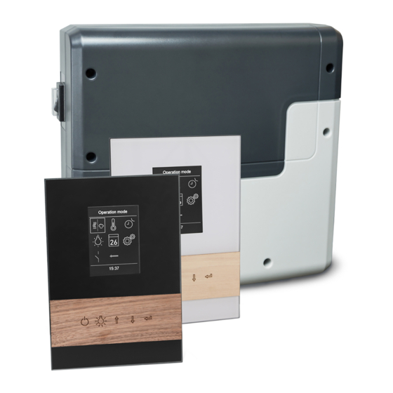
- Page 1 I N N O V A T I V E S A U N A T E C H N O L O G Y EmoStyle Di EmoStyle Hi sauna control unit Installation and operation manual Made in Germany Firmware R3.50 IPx4 Print no.
-
Page 2: Table Of Contents
English Contents Preface and general information about sauna bathing ................4 General safety precautions ..........................5-6 Scope of delivery ..............................7 Accessories ................................7 Technical data ............................... 8-9 Intended use ................................9 Installation ................................ 10-17 Main electronic unit ..........................10-11 Control panel - location and cable connection ..................12 Control panel - voltage regulator ......................13 Control panel - flush-mounted installation ................... - Page 3 Manual setting of the lamp ..........................41 Service ................................42-46 Service- and Setup ............................42 Symbol description ............................43 Settings ..............................44-46 Troubleshooting (error messages) ........................47 The ”switch-off“ rocker switch ..........................48 Recycling ..................................49 Service Address ..............................49 General Terms and Conditions of Service .....................50...
-
Page 4: Preface And General Information About Sauna Bathing
Preface Dear customer, quickly and easily find your way though the programming process. Please note the varia- you have purchased a high-quality electronic tion in temperatures in the cabin while sauna device with which you will enjoy your sauna for bathing. -
Page 5: General Safety Precautions
General safety precautions temperature setting. The temperature can be held within operating parameters and This device may be used by children (age • a minimal deviation at the bench level of 8 and above) and by persons with reduced the sauna cabin can be achieved only if the physical, sensory, or mental disabilities, or device is installed correctly. - Page 6 ! When designing the sauna cabin, en- ! Attention! sure that the external exposed glass surfaces Dear customer, may only reach a maximum temperature of according to the valid regulations, the 76 °C. If necessary, protective features need electrical connection of the sauna heater to be fitted.
-
Page 7: Scope Of Delivery
Scope of delivery Check the device for completeness upon receipt. The delivery includes: Main electronic unit (with two-part front cover) Control panel with colour display Voltage regulator Housing base for flush-mounted installation of the control panel De-installation tool (for control panel) Temperature sensor: a) housing, b) sensor board, c) overheat protection fuse, d) 2 mounting screws 4 x 40 mm, e) connection cable 5 m with RJ10 plug, f ) 2-core white cable for overhea- ting protection fuse 5 m... -
Page 8: Technical Data
Technical data Voltage (power supply): 400 V 3 N AC 50 Hz Switching capacity: max. 9 kW resistive load, may be extended with a power extension unit (LSG) Fuse 3 x 16 A Heating time limit: 6 h / 12 h / unlimited Housing: plastic, shatter-resistant Display:... -
Page 9: Intended Use
Card reader: Micro-SD card reader in control panel Ambient temperatures: -10°C bis +35°C Storage temperatures: -20°C bis +60°C Place of installation requirement: Intended for indoor installation only. Sensors - may not be installed in corrosive or highly salty environment. Device - may not be installed in corrosive environment or in an environment which may cause water condensation. -
Page 10: Main Electronic Unit
Installation of the main electronic unit The main electronic unit (relay box) may be installed only outside the sauna cabin. The recom- mended places of installation are the outer sauna wall or the engineering room (plant room). If empty ducts for connection cables are already available, then they usually predetermine the in- stallation position. - Page 11 Hang the housing on the upper central screw in the upper central mounting hole. Insert the supplied rubber cable glands into the openings of the bottom of the housing (from below or from behind, as desired) and then guide the connection cables through these open- ings.
-
Page 12: Installation
Control panel Cable connection Location Lay the connection cable from the relay box to the control panel. The control panel may be mounted inside the The connection cable may be laid only be- sauna cabin on the sauna wall. If ductwork is al- tween the outer sauna wall and insulation layer ready provided for electrical installations then to prevent overheating (fig. -
Page 13: Control Panel - Voltage Regulator
Voltage regulator Voltage regulator The control panel is equipped with an external Connect voltage voltage regulator. This component is located regulator here in a small separate metal housing and is con- nected to the control panel by cable. The voltage regulator may be placed e.g. on the sauna roof. -
Page 14: Control Panel - Flush-Mounted Installation
Flush-mounted installation (wall-mounting) = Dimensions must be strictly adhered to Wall aperture: Hight: 189 mm Width: 128 mm Depth: min. 37 mm alle Maße in mm Notice: Please pay attention to the correct orientation of the bottom housing. The con- nection cable duct must be at the bottom side (see fig. - Page 15 Installation of the housing upper part (control panel with display) Bauteil Voltage regulator use tool here The voltage regula- tor must be mounted within a radius of ap- prox. 3 m (cable length) away from the control panel. Fig. 10 Fig.
-
Page 16: Installation Of The Temperatur Sensor
Connection of sensor cables Do not lay sensor and power supply lines together, or lead them through the same duct. This can lead to interferences in the electronics, such as “fluttering” in the relays. Connect the cable shield- ing (if present) to ground in the control unit. Please observe that the following dimensions relate to the values stipulated during the unit in- spection acc. - Page 17 Lead the sensor cable (red) and the limiter cable (white) through the drilled hole and connect both cables to the main relay box. Connect the sensor cable to the sensor board according to fig.15. Make sure the connections are correct. Connect the limiter cable (2-core white cable) to the limiter board (STB). Mount the sensor to the ceiling plank using two supplied screws and attach the housing cover.
-
Page 18: Electrical Connection
Electrical connection Sauna heater connection The electrical connections may only be car- ried out by a certified electrician in compli- ance with the guidelines of the local power Install the sauna heater and the vaporizer in supply company and applicable legal regu- front of the air intake according to the manu- lations (e.g. -
Page 19: Sauna Lamp Connection
Sauna lamp connection Heating time limitation The maximal heating time may be limited with The sauna lamp must have the protection the jumper #5 on the main board of the relay class of at least IPx4 and should be resistant to box. -
Page 20: Installation Diagram And Terminal Layout
Installation diagram Emotec D / Emostyle D/Di Steckeranschluß Fühler Sensor plug connector Bankfühler/2nd Sensor Ofenfühler/Sensor reserviert Leistungsteil Sensorbus Main unit (relay box) Relais box Saunabus light S1 S1 N L1 L2 L3 N W V U N L N L N Leuchte/light Lüfter/fan Bedienteil Control panel... - Page 21 Installation diagram Emotec H / Emostyle H/Hi Feuchtefühler Steckeranschluß Fühler humidity sensor Sensor plug connector Bankfühler/2nd Sensor Ofenfühler/Sensor reserviert Leistungsteil Sensorbus Main unit (relay box) Relais box Saunabus light S1 S1 N L1 L2 L3 N W V U N L N L N Leuchte/light Lüfter/fan Bedienteil...
-
Page 22: Temperature Sensor
Temperature sensor ! ATTENTION! Feuchtefühler Humidity sensor Bankfühler Connecting a sensor to the sauna bus 2nd sensor Ofenfühler reserviert connector (RJ12) may damage the sensor Main sensor reserved and the main board of the control unit! Sensorbus RJ 10 The sensors are connected via RJ10 modular plugs to one of the corresponding sensor bus RJ10 jacks on the main board of the relay box, Saunabus... -
Page 23: Overview - Connection Scheme (Emotec D/H, Emostyle D/Di And H/Hi)
Overview - connections at Emotec D / EmoStyle D/Di = optional (STB) Erweiterungsmodule Extension modules Leistungsteil Bedienteil Modules (additifs) Main unit (relay box) Control panel Relais box Tableau de commande 6P4C <-> 4P4C 6P4C <-> 4P4C 400 V 3N AC 50 Hz Overview - connections at Emotec H / EmoStyle H/Hi = optional (STB) -
Page 24: Humidity Sensor Installation
Humidity Feuchtefühler Humidity sensor Bankfühler sensor installation 2nd sensor Ofenfühler reserviert Main sensor reserved Sensorbus RJ 10 1. The humidity sensor shall be mounted in the Connection over- middle of the wall opposite to the heater at view of tempera- Saunabus ture sensor, bench approx. -
Page 25: Vaporizer Connection
Vaporizer connection ! Attention: Always connect the neutral (N) terminal at the sauna heater. In humid mode one phase will be switched off, the Only for “H“ series sauna control units. power load distribution will not be propor- tional. As a result the N line will not be cur- ATTENTION: pay particular attention to rentless. -
Page 26: Installation Of The Optional Bench Sensor
Installation of the The sensor symbol will be displayed either on the start screen (Emotec, EmoStyle models) or optional bench sensor in the temperature query submenu (EmoTouch models). If the bench sensor is faulty, the temperature Place of installation: The 2nd sensor (bench will be controlled via the main sensor over the sensor) shall be mounted to the ceiling, over heater. -
Page 27: Setup (Commissioning / First Switching)
Setup (commissioning / first switching) Using the control unit for the first time or after a reset The EmoStyle control unit offers a fast and intuitive setup upon the first switching or after a full system reset. Select language Sprache Select the required language with the buttons and confirm your selection by pressing briefly on the enter button... - Page 28 The setup is now complete and the control unit will switch to standby mode. 20:51 20:51 Display in standby mode for Display in standby mode for dry (Finnish) sauna operation humid (Bi-O) sauna operation (EmoStyle D/Di und H/Hi). (nur EmoStyle H/Hi). Cabin light switched on.
-
Page 29: Operation
Operation Control panel - overview Sauna (heating) on / off Sauna heater Press for 3 sec to switch the heater on (dry finnish mode if the cloud symbol Light is not shown) on / off Humid opera- tion Up / Down 09:12 % sign - humidity Selection in the Menu... -
Page 30: Symbol Description (Main Navigation Menu)
Operation principle Press the button , in order to select a function (icon). Press shortly the ENTER button open this function. Press the buttons to change the value (changed value turns from white to green). Press the ENTER button to save (confirm) the setting and exit, the control panel will then return to the previous (upper) menu. -
Page 31: Graphic User Interface
Graphic user interface (GUI) and the current climate conditions check Thanks to the modern graphic user interface, you can quickly access all functions and make nec- essary settings, as well as make a simple instant query for the current sauna climate condition. The symbols on the start screen may be displayed in different colours, in order to indicate the cur- rent operation status - e.g. -
Page 32: Operation And Program Settings
Operation and program settings Sauna on / off Press the button on the control panel for approx. 3 seconds to switch the sauna on. Count- down runs . The display will show the active heating state (see previous page). The cabin light will be also switched on. - Page 33 Please observe that with a humidity sensor, the humidity rH [%] setting will depend on the pre-set temperature. For safe- ty reasons only the values to the left and under the curve may be selected. For instance at 60 °C temperature you can set up to 40 % rel.
- Page 34 Timer Timer Timer (switch-on time pre-selection) The timer function allows you to have your sauna switched on automatically with the desired climate condition. You have two possible options: Auswahl Einzeltermin - single event (single time switching, not recurrent) 20:51 20:51 - week timer (regular, recurrent switching for the given day of the week, e.g.
- Page 35 Now select the program (1 of 4) and press the ENTER button. Set the required start time (hours and minutes) - e.g. 9:30. Set the required heating time (hours and minutes) - e.g. 3:30. Set the required operation type - dry Finnish sauna or humid sauna (only Emostyle Hi) Set the required temperature.
- Page 36 HOT-function With the HOT-function you can give an additional performance boost in the sauna where the sau- na heater will heat without interruption for a preset time (5 - 20 minutes). The set-point tempera- ture is increased to 115 °C, the cabin fan runs at full speed. The maximum temperature 115 °C is not exceeded for safety reasons.
-
Page 37: Symbol Description (Extended Settings)
Symbol description - extended settings The submenu “extended settings“ provides a range of additional functions, which normally need to be set only once or quite seldom. Select the symbol in the main menu and shortly press the ENTER button Language Time Allows to set the language for the menu navi- Here you can set the time of day. -
Page 38: Extended Settings
This setting defines the period of time after which the control panel will enter the screensaver mode if no button has been operated. In this mode the display brightness will be reduced to the minimum and the display will show the current time (or EOS-Logo et al enlarged) floating across the screen. Press the button or press on the on/off button shortly in order to return to the start screen. - Page 39 jump to the next digit. After the 4 digit confirmation the display will return to the start screen and the unit is now locked. No settings are possible. For safety reasons it is still possible to switch off the heater (interrupt active heating) and to switch the light while the unit is locked.
- Page 40 Operation data Here you can check the important information concerning your control unit (sauna) operation. Firmware - allows to check the currently installed firmware version. Press the UP/DOWN button to switch between two possible parameters. “Panel Vx.xx“ - shows the firmware in con- trol panel, “Mod-LS Vx.xx“...
-
Page 41: Manual Setting Of The Lamp
Manual setting of the lamp The control unit is factory set to inductive lighting load. Hence, resistive loads can also be control- led. If required, the light output can also be switched manually to capacitive loads. When using incandescent lamps, the lighting load must remain set to inductive load. The current setting is shown on the display. -
Page 42: Service
Service- and Setup The control unit provides an extensive scope of functions for setup and fine-tuning of the sauna equipment, in order to optimize sauna operation. This setup menu is protected with a PIN code and should not be accessible to the end users. Hint: a short version of the operation manual without setup and installation is included in the delivery. -
Page 43: Symbol Description
Symbol description Service / maintenance intervals Temperature adaptation Setting the intervals for service / maintenance. Setting for the temperature offset +/- °C. HOT-time Setting in minutes (5-20 min.) Fan speed settings. Only for dry Finnish operation. Refilling time HOT-auto interval time Switch-off time settings (only for EmoStyle H/Hi) Setting range: 30 to 480 min. -
Page 44: Settings
Settings Service intervals Allows to set the intervals for servicing and maintenance. Upon expiry the control panel will re- mind the user for a short time upon every switching about the pending servicing. The end user can check the remaining time to the next servicing in the extended settings menu. This function allows as well to keep track of the total operation time of the sauna. - Page 45 Attention! The smaller hysteresis value will lead to considerably increased number of relay switch- ings, which reduces the service life expectation of the control unit! The factory default setting is 5K. Usage Here you can set the sauna use type to private use or commercial use. The control unit will adjust relevant settings accordingly.
- Page 46 HOT-auto interval time You can start the HOT-function automatically at specific time intervals. In this menu the interval for this automatic switch-on can be set. However, the HOT-heat-up phase starts effectively a little earlier, before the set time according to the set duration.
-
Page 47: Troubleshooting (Error Messages)
• Check cable connections and restart the control unit; if the fault persists, contact the dealer or EOS service. If any other unidentified error messages appear, please contact EOS service. Make sure to supply the serial number, fault details and other relevant information. -
Page 48: The "Switch-Off" Rocker Switch
The “switch-off“ rocker switch The control unit is equipped with a “switch-off” rocker switch. You will find this switch on the left side of the main relay box. This switch allows to switch the control unit to standby mode (notice the heating will not start), to switch the control unit completely off (disconnect from power) or to switch the con- rocker switch... -
Page 49: Recycling
2012/19/EU. Do not dispose it with the normal household waste. Service Address: EOS Saunatechnik GmbH Schneiderstriesch 1 35759 Driedorf, Germany Tel: +49 (0)2775 82-514 Fax: +49 (0)2775 82-431 [email protected]... -
Page 50: General Terms And Conditions Of Service
The manufacturers General Terms and Conditions of Business, which can be found at www.eos-sauna.com/ V. Liability agb, shall apply in addition to the foregoing terms and conditions of service.