Table of Contents
Quick Links
Table of Contents

Related Manuals for Honeywell Sensepoint XCD RFD


Summary of Contents for Honeywell Sensepoint XCD RFD
- Page 1 Technical Handbook Sensepoint XCD RFD (Remote Flammable Detector)
-
Page 2: Safety
WARNINGS Sensepoint XCD RFD is designed for installation and use in Zone 1 or 2 hazardous areas in many countries including Europe, and for Class I, Division 1, Groups B, C & D Hazardous Areas in the Americas. -
Page 3: Information
The Start-up/Surge/In rush current is dependant on the type of power supply used. The typical start-up current for Sensepoint XCD RFD is less than 800mA. Measure the start- up current using the specific power supply before installation to ensure suitability for your application. -
Page 4: Table Of Contents
Sensepoint XCD RFD Technical Manual SPXCDHMRFEN Issue 4_08-2016 3 Table of contents 1 Safety ..........................2 2 Information ........................3 4 Introduction ........................6 4.1 Transmitter ........................7 4.2 Flammable Gas sensors .....................7 4.2.1 Sensepoint XCD flammable gas sensors ...............8 4.2.2 Sensepoint LEL Flammable gas sensors ...............8 4.2.3 705 LEL flammable gas sensors (UL approved) ............9... - Page 5 17.4 Collecting Cone Drawing ..................57 17.5 Mounting Bolt Assy Drawing .................. 58 17.6 Mounting Bracket Drawing ..................55 17.7 Sensepoint XCD RFD Sensor ................59 17.8 Control Drawing ..................... 61 18 Certification......................... 63 18.1 China GB Ex and PA ....................63 18.2 Korea KTL ......................
-
Page 6: Introduction
The construction of Sensepoint XCD RFD allows it to be used in hazardous area locations; it may also be used in other areas not classified as hazardous. Sensepoint XCD RFD is suitable for use in Zone 1 or 2 hazardous areas (International). -
Page 7: Transmitter
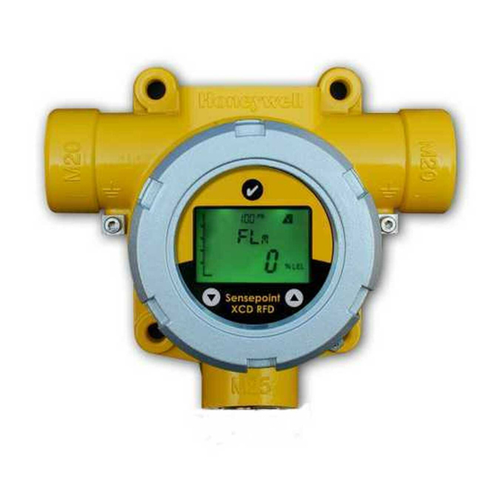
Diagram 2: Sensepoint XCD RFD Display and Magnetic Switches 4.2 Flammable Gas sensors Sensepoint XCD RFD is designed to work with the flammable sensors from the Sensepoint XCD, 705 and Sensepoint sensor ranges. Sensepoint XCD sensors use NDIR infrared and electro-catalytic technologies. The Sensepoint XCD range is ATEX approved for use throughout Europe and many parts of the world. -
Page 8: Sensepoint Xcd Flammable Gas Sensors
The sensor is available with M25 thread. M20 or ¾” NPT threads are options. Details of connecting these sensors with the Sensepoint XCD RFD transmitter are given in sections 5 and 6. For more sensor specific details, refer to the Technical Handbook Part No. -
Page 9: 705 Lel Flammable Gas Sensors (Ul Approved)
1% LEL, depending on the gas being detected. The sensor is available with ¾”NPT thread only. Details of connecting these sensors with the Sensepoint XCD RFD transmitter are given in sections 5 and 6. For more sensor specific details, refer to the 705 Combustible Gas Sensor Operating Instructions Part No: 00705M5002. -
Page 10: Accessories
SPXCDHMRFEN Issue 4_08-2016 4.3 Accessories A range of accessories are available to allow use of Sensepoint XCD RFD in a wide variety of applications. These include Pipe mounting bracket, Sunshade deluge cover, Sensor collecting cone, Sensor flow Housing and Remote sensor mounting junction boxes. -
Page 11: Options
Sensepoint XCD RFD Technical Manual SPXCDHMRFEN Issue 4_08-2016 4.4 Options ® 4.4.1 Modbus ® One of the most common field buses in the industry, the optional Modbus interface allows the XCD to connect to a bus of devices and transmit data to PLCs or controllers (see Appendix A). - Page 12 Sensepoint XCD RFD Technical Manual SPXCDHMRFEN Issue 4_08-2016 (MODBUS ID SETTING) Set id>>Set Modbus slave ID>>Set Baud rate>>Set Parity 1) Slave ID shall be set 1~247 2) Baud rate setting 9600 or 19200 3) Parity setting (No, Even, Odd) From the Configuration Mode screen, select‘’. To set the Modbus Slave ID, use the up-down ‘’switches to move to the desired position and use ‘’to select it.
-
Page 13: Installation
17. WARNINGS Sensepoint XCD RFD is designed for installation and use in Zone 1 or 2 hazardous areas in many countries including Europe, and for Class I, Division 1, Group B,C & D Hazardous Areas in the Americas. -
Page 14: Mounting And Location
The agreement reached on the location of detectors should be recorded. 5.2 Mounting the transmitter The Sensepoint XCD RFD transmitter has an integral mounting plate consisting of four mounting holes on the transmitter body. The transmitter may be fixed directly to a surface mounting, or to a horizontal or vertical pipe/structure, 40.0-80.0mm (1.6 to 3.1 inches) in... -
Page 15: Installing The Sensor
2. Connect the cable to the transmitter enclosure via the bottom entry. 3. Cable (non conduit) based installations must use appropriately certified cable glands. Refer to the Sensepoint XCD RFD Control Drawing 3001EC091 shown in section 17 for conduit based installation in the Americas. - Page 16 Sensepoint XCD RFD Technical Manual SPXCDHMRFEN Issue 4_08-2016 Sensepoint XCD RFD with Sensepoint XCD remote plug-in sensor It is necessary to use a ferrite filter at the remote sensor to reduce electromagnetic interference. The ferrite filter (supplied) should be fitted as follows: 1.
-
Page 17: Electrical Connections
6 Electrical connections WARNINGS Sensepoint XCD RFD is designed for installation and use in Zone 1 or 2 hazardous areas in many countries including Europe, and for Class I, Division 1, Group B,C & D Hazardous Areas in the Americas. -
Page 18: Transmitter Wiring
Caution: All electrical connections should be made in accordance with any relevant local or national legislation, standards or codes of practice. The Sensepoint XCD RFD transmitter may be wired in either Current SOURCE or Current SINK configuration. These two options are offered to allow greater flexibility in the type of control system that it can be used with. -
Page 19: Terminal Connections
Note: Terminal Blocks are Terminal block for plug/socket type Sensepoint or 705 and may be Flammable sensor removed to ease wiring. Diagram 6: Sensepoint XCD RFD Terminal module Terminal Module Connections Terminal Marking Connection Description Number +VE Supply(12-32VDC) -VE Supply(0VDC) -
Page 20: Power
Sensepoint XCD RFD Technical Manual SPXCDHMRFEN Issue 4_08-2016 6.3 Power for UL/CSA Version The Sensepoint XCD transmitter(U L /CSA versions)requires a power supply from the controller of between 12Vdc and 32Vdc. Ensure that a minimum supply of 12Vdc is measured at the sensor, taking into account the voltage drop due to cable resistance. -
Page 21: Cabling
Sensepoint XCD RFD Technical Manual SPXCDHMRFEN Issue 4_08-2016 6.4 Cabling The use of industrial grade, suitably armoured field cable is recommended. For example, screened 3 cores (plus screen 90% coverage), suitably mechanically protected copper cable with a suitable M20 explosion-proof gland with 0.5 to 2.5 mm2 (20 to 13 AWG) conductors. -
Page 22: Ground Terminal Wiring
Sensepoint XCD RFD Technical Manual SPXCDHMRFEN Issue 4_08-2016 The Earth Screen of the field cable should be “tied to Earth” or connected to Ground at one point only. It is common practise to adopt a STAR EARTH connection regime where all instrumentation Screens are connected at one common point. -
Page 23: Default Configuration
Sensepoint XCD RFD Technical Manual SPXCDHMRFEN Issue 4_08-2016 7 Default configuration The Sensepoint XCD RFD transmitter is supplied with the following default configuration. Function Value/Setting Meaning XCD RFD recognizes the XCD RFD sensor cartridge Automatic for Sensepoint XCD RFD according to the gas type within its own sensor family Sensor Type sensors. -
Page 24: Normal Operation
SPXCDHMRFEN Issue 4_08-2016 8 Normal Operation Sensepoint XCD RFD is supplied configured and ready for use according to the “Default Settings” table shown above. However these setting may be tailored to a specific application requirement using the Sensepoint XCD RFD configuration menu system. -
Page 25: System Status
Sensepoint XCD RFD Technical Manual SPXCDHMRFEN Issue 4_08-2016 8.2 System Status Display indications, current output and relay states for various operational conditions are shown in the following table. For further details of error messages and trouble shooting see section 12.3. -
Page 26: Magnetic Wand Activation
Communication with the XCD RFD is achieved by positioning the Magnetic Wand at one of three different positions on the front glass window of the Sensepoint XCD RFD transmitter. Activation of the switches is verified by observing the Magnetic Wand Activation Icon on the LCD display... -
Page 27: First Time Switch On (Commissioning)
Sensepoint XCD RFD Technical Manual SPXCDHMRFEN Issue 4_08-2016 9 First time switch on (Commissioning) WARNING The following procedure requires the Transmitter Cover to be removed while carrying out supply voltage checks. Therefore the appropriate permits to work should be sought in preparation. - Page 28 Sensepoint XCD RFD Technical Manual SPXCDHMRFEN Issue 4_08-2016 Note: For a full description of each screen shown in Diagram 12, please refer to Section 13.3 “Review Mode” of this Manual. Diagram 12: Normal Start up procedure (For the Flammable sensor version) 11.
-
Page 29: Response Check And Calibration
If no residual gas is present then the background air can be used to perform the zero calibration. Contact your Honeywell Analytics representative for details of suitable calibration kits. - Page 30 Sensepoint XCD RFD Technical Manual SPXCDHMRFEN Issue 4_08-2016 (ZERO CALIBRATION) WARNING When calibrating the Sensepoint XCD Flammable IR or CO IR sensors, it is essential that the zero calibration is always followed by a span calibration. The zero calibration must never be done alone.
- Page 31 Sensepoint XCD RFD Technical Manual SPXCDHMRFEN Issue 4_08-2016 (SPAN CALIBRATION) 11.The display shows the current calibration span gas concentration while flashing the ‘ ’ icon. Use ‘ ’ to change the calibration span gas concentration, and ‘ ’ when ...
- Page 32 Sensepoint XCD RFD Technical Manual SPXCDHMRFEN Issue 4_08-2016 19.Promptly switch off the calibration span gas and remove the Sensepoint XCD Gassing Cap from the sensor to allow the gas to disperse. 20.When the reading falls below 50% of the calibration gas level the display indicates a countdown .
-
Page 33: General Maintenance
Sensepoint XCD RFD Technical Manual SPXCDHMRFEN Issue 4_08-2016 11 General Maintenance WARNINGS Access to the interior of the transmitter, when carrying out any work, must only be conducted by trained personnel. Care should be taken when removing and refitting the Sensepoint XCD plug-in Sensor Cartridge to the Sensor Socket so that damage to the connection pins can be avoided. -
Page 34: Servicing
A fault condition will be signalled by the detector if the sensor is removed with the unit under power. 12.1 Sensor replacement The sensors that are used with the Sensepoint XCD RFD have no serviceable parts. When they have reached the end of their operational life, simply replace the sensor or the sensor cartridge. - Page 35 To replace remote sensor of a Sensepoint XCD Flammable Sensor Socket use the following procedure: 1. Important: Remove the Power from the Sensepoint XCD RFD Transmitter 2. Remove other accessories from the sensor socket thread. 3. Remove the Sensor Retainer with locking screw.
-
Page 36: Replacing Modules Within The Transmitter
Sensepoint XCD RFD Technical Manual SPXCDHMRFEN Issue 4_08-2016 12.2 Replacing Modules within the Transmitter Two replaceable module assemblies are located within the transmitter housing. The Display Module and the Terminal Module. The Display Module is simply removed by unplugging it from the Terminal Module (this procedure is done during normal installation). -
Page 37: Faults And Warnings
Sensepoint XCD RFD Technical Manual SPXCDHMRFEN Issue 4_08-2016 12.3 Faults and Warnings The table below provides details of possible error. Message Description Action The unit has not been calibrated for the configured calibration interval W-01 Calibration needed Calibration is necessary due to change... -
Page 38: Menu's And Advanced Configuration
Sensepoint XCD RFD Technical Manual SPXCDHMRFEN Issue 4_08-2016 13 Menu’s and Advanced Configuration 13.1 Abort Function In Review Mode or Configuration Mode the user can escape one step back from the current position using the Abort Function. To do this the user must activate the Enter switch for more than 3 seconds with the Magnetic Wand. - Page 39 Sensepoint XCD RFD Technical Manual SPXCDHMRFEN Issue 4_08-2016 Menu Display Description Execute zero/span calibration Set calibration gas level Set Calibration After zero, the option exists to proceed with span calibration, or return to the Menu. Select the type of sensor from the sensor Select Sensor list.
- Page 40 Sensepoint XCD RFD Technical Manual SPXCDHMRFEN Issue 4_08-2016 Configure relay on delay time, relay off Relay Operation delay time and latch/non-latch Set Location Set location (or TAG number) Change temperature display unit. Set Temperature Unit °C (Celsius) or °F (Fahrenheit)
- Page 41 Sensepoint XCD RFD Technical Manual SPXCDHMRFEN Issue 4_08-2016 Monitoring Mode Menu Switch ( > 3 Seconds) Quit/ESC command Auto quit after no activity of timeout Access permitted? Abort Release mA O/P Inhibit mA O/P Force Current Set Calibration Set Alarms...
- Page 42 Sensepoint XCD RFD Technical Manual SPXCDHMRFEN Issue 4_08-2016 13.2.1 Configuration mode operation table Configuration mode allows the user to perform calibration and configure parameters such as full scale range, calibration gas level, calibration interval, inhibit current & timeout, alarm settings, relay settings, set a password, etc. To activate Configuration mode hold the magnet over the ENTER switch for at least 3 seconds and then remove.
- Page 43 Sensepoint XCD RFD Technical Manual SPXCDHMRFEN Issue 4_08-2016 PEAK READING CURRENT GAS DISPLAYED WITH OUTPUT CONCENTRATION INHIBITED ‘ ’ ICON AND DISPLAYED WITH bumP UNIT RETURNS TO PEAK STRING FLASHING. OUTPUT INHIBITED ‘ ’ tESt MENU MODE APPLY BUMP TEST ICON FLASHING.
-
Page 44: Sensor / Gas Selection
Sensepoint XCD RFD Technical Manual SPXCDHMRFEN Issue 4_08-2016 13.3 Sensor / Gas Selection 13.3.1 Sensor Selection “Select Sensor” sets the identity of the type of mV sensor attached to the XCD RFD when it does not detect the sensor type automatically. - Page 45 Sensepoint XCD RFD Technical Manual SPXCDHMRFEN Issue 4_08-2016 Ir-5* Ir-7 Methane Ir-8* Propane ProP *Contact Honeywell Analytics for availability Gas selection is dependent on the type of sensor attached to the XCD RFD. If Ir-7 sensor is attached, then a user can only select ‘mEt’ gas respectively. But when Cb-3/Cb-4 sensor is attached to the XCD RFD, a user can select the gas from Str1 (1*) to Str8 (8*).
-
Page 46: Review Mode
Sensepoint XCD RFD Technical Manual SPXCDHMRFEN Issue 4_08-2016 13.4 Review Mode The instrument will enter Review mode when the “Enter” switch is activated with the Magnetic Wand and held for around one second. Names, displays and descriptions for each review item in Review Mode are shown in the following table. - Page 47 Sensepoint XCD RFD Technical Manual SPXCDHMRFEN Issue 4_08-2016 Location Location in which the transmitter is installed Power Power voltage* Temperature Internal Transmitter temperature* Peak conc. Maximum concentration detected up to now Test Result There is no fault detected. Table 13: Transmitter menu descriptions...
- Page 48 Sensepoint XCD RFD Technical Manual SPXCDHMRFEN Issue 4_08-2016 Menu Switch (1s to 3s) Review Monitoring Mode Mode Auto end to cycle S/W Version Test Result 2 second delay 2 second delay SRS Version Peak Reading 2 second delay 2 second delay...
-
Page 49: General Specification
* Extended operating temperature range of -40°C to +65°C (-40°F to +149°F) for all sensor except for IR, with an accuracy of +/- 30% of applied gas from -20°C to -40°C (-4°F to -40°F) and +55°C to +65°C (+131°F to +149°F). Long term operation at this range may cause decline in sensor performance. Contact Honeywell Analytics for any additional data or details. Certification China GB Ex d IIC T4 GB3836.1&2 -2000, PA, CCCF... -
Page 50: Ordering Information
Sensepoint XCD RFD Technical Manual SPXCDHMRFEN Issue 4_08-2016 15 Ordering information Part number Description Sensepoint XCD RFD transmitter (LM25) SPXCDALMRFD ATEX/IECEx/AP* approved SP XCD RFD Transmitter with LM25, M20 Entry, without MODBUS SPXCDULNRFD cCSAus approved SP XCD RFD Transmitter with LM25, 3/4“NPT Entry, without MODBUS... - Page 51 Sensepoint XCD RFD Technical Manual SPXCDHMRFEN Issue 4_08-2016 02000-A-1640 Nylon Weather Protection Housing for Sensepoint Combustible Sensors 02000-A-1635 Weather Protection Housing for 705 Sensors 1283-1047 Duct Mount Adaptor Assembly Sensepoint XCD Spares SPXCDDMR Replacement display module for RFD (4~20mA), without MODBUS...
-
Page 52: Warranty Statement
Analytics reserves the right to charge for any site attendance where any fault is not found with the equipment. Honeywell Analytics shall not be liable for any loss or damage whatsoever or howsoever occasioned which may be a direct or indirect result of the use or operation of the Contract Goods by the Buyer or any Party. -
Page 53: Installation Drawing
Sensepoint XCD RFD Technical Manual SPXCDHMRFEN Issue 4_08-2016 17 Installation Drawing 17.1 Mechanical Installation Drawing... -
Page 54: Electronic Connection Drawing
Sensepoint XCD RFD Technical Manual SPXCDHMRFEN Issue 4_08-2016 17.2 Electronic Connection Drawing... - Page 55 Sensepoint XCD RFD Technical Manual SPXCDHMRFEN Issue 4_08-2016...
-
Page 56: Duct Mounting Drawing
Sensepoint XCD RFD Technical Manual SPXCDHMRFEN Issue 4_08-2016 17.3 Duct Mounting Drawing... -
Page 57: Collecting Cone Drawing
Sensepoint XCD RFD Technical Manual SPXCDHMRFEN Issue 4_08-2016 17.4 Collecting Cone Drawing... -
Page 58: Mounting Bolt Assy Drawing
Sensepoint XCD RFD Technical Manual SPXCDHMRFEN Issue 4_08-2016 17.5 Mounting Bolt Assy Drawing... -
Page 59: Mounting Bracket Drawing
Sensepoint XCD RFD Technical Manual SPXCDHMRFEN Issue 4_08-2016 17.6 Mounting Bracket Drawing... -
Page 60: Sensepoint Xcd Rfd Sensor
Sensepoint XCD RFD Technical Manual SPXCDHMRFEN Issue 4_08-2016 17.7 Sensepoint XCD RFD Sensor... -
Page 61: Control Drawing
Sensepoint XCD RFD Technical Manual SPXCDHMRFEN Issue 4_08-2016 17.8 Control Drawing... - Page 62 Sensepoint XCD RFD Technical Manual SPXCDHMRFEN Issue 4_08-2016...
-
Page 63: Certification
Sensepoint XCD RFD Technical Manual SPXCDHMRFEN Issue 4_08-2016 18 Certification 18.1 China GB Ex and PA China GB Ex (Chinese Version):... - Page 64 Sensepoint XCD RFD Technical Manual SPXCDHMRFEN Issue 4_08-2016 China GB Ex (English Version):...
- Page 65 Sensepoint XCD RFD Technical Manual SPXCDHMRFEN Issue 4_08-2016 China PA Certification:...
-
Page 66: Korea Ktl
Sensepoint XCD RFD Technical Manual SPXCDHMRFEN Issue 4_08-2016 18.2 Korea KTL... -
Page 67: European Atex
Sensepoint XCD RFD Technical Manual SPXCDHMRFEN Issue 4_08-2016 18.3 European ATEX ATEX For Transmitter:... - Page 68 Sensepoint XCD RFD Technical Manual SPXCDHMRFEN Issue 4_08-2016 ATEX for Sensor...
-
Page 69: International Iec
Sensepoint XCD RFD Technical Manual SPXCDHMRFEN Issue 4_08-2016 18.4 International IEC IEC Ex for Transmitter... - Page 70 Sensepoint XCD RFD Technical Manual SPXCDHMRFEN Issue 4_08-2016 IEC Ex for Sensor...
-
Page 71: Sensepoint Xcd Atex Name Plate
Sensepoint XCD RFD Technical Manual SPXCDHMRFEN Issue 4_08-2016 18.5 Sensepoint XCD RFD cCSAus Name Plate... -
Page 72: Sensor Cartridges Label
Sensepoint XCD RFD Technical Manual SPXCDHMRFEN Issue 4_08-2016 18.6 Sensor Cartridges Label... -
Page 73: Cross Interference And Cross Calibration
Sensepoint XCD RFD Technical Manual SPXCDHMRFEN Issue 4_08-2016 19 Cross Interference and Cross Calibration 19.1 Cross Calibration Flammable Gas Detector For greater accuracy, a catalytic gas detector should be calibrated using a certified gas/air mixture equal to 50% LEL of the actual target gas intended to be monitored. - Page 74 Sensepoint XCD RFD Technical Manual SPXCDHMRFEN Issue 4_08-2016 Pentane Propane Propan-2-ol Styrene Tetra hydrafuran Toluene Triethylamine Xylene Table 14 . Star Rating of Gases To cross calibrate the Sensepoint XCD flammable gas detector: (1) Obtain the star rating for both the calibration test gas and the gas to be detected from...
- Page 75 Section 19.1 is used for Sensepoint XCD Catalytic Sensor only, please refer to Sensepoint Technical Manual for using Sensepoint flammable gas sensors. Please contact your local Honeywell Analytics sales or service distributor, or regional offce should further clarification or additional information be required.
-
Page 76: Meter Multiplication Factors For Sensepoint Xcd-Ir Propane
NOTE Honeywell Analytics recommends that users verify the accuracy of their instruments using test gasses wherever possible. Cross-referred measurements should be used as a guide only, not as absolute values. -
Page 77: Modbus And The Xcd
Sensepoint XCD RFD Technical Manual SPXCDHMRFEN Issue 4_08-2016 XCD Transmitter Appendix A - Modbus® Protocol A-2 A.1 Modbus and the XCD The XCD gas detector may be fitted with the optional Modbus board. Authoritative information on the MODBUS Upgrade Kit can be found at www.modbus.org. The XCD supports Modbus/RTU over an RS-485 physical layer. -
Page 78: Modbus Registers
Sensepoint XCD RFD Technical Manual SPXCDHMRFEN Issue 4_08-2016 A.2 Modbus Registers ModBus Register Information Type Size Note Address 30001 Main SW Version of XCD 30002 EEP Version of XCD 30003 WatchDog s/w Version of XCD 30004 Location string string[12] 30010... - Page 79 www.norrscope.com...