
Related Manuals for Siemens VDO DTCO 1381


Summary of Contents for Siemens VDO DTCO 1381
-
Page 1: Technical Description
Digital Tachograph Technical Description DTCO 1381 (Rel. 1.2a) www.siemensvdo.com TD00.1381.00 132 102... - Page 2 The information, descriptions, data and illustrations in this technical description may be changed without prior notice and do not rep- resent any liability on the part of the Siemens VDO Automotive AG. The description is based on the most recent operating system and program versions at the time of printing.
-
Page 3: Overview Of Changes
Overview of changes Overview of changes Date Chapter Page Topic, Measure 12.2005 First edition 04.2006 New edition DTCO 1381 – Release 1.2 06/2007 New edition DTCO 1381 – Release 1.2a Item no. changed to TD00.1381.00 132 102 Edition 07/2007 Technical Description DTCO 1381... - Page 4 © Siemens VDO Automotive AG Edition 07/2007...
-
Page 5: Table Of Contents
Table of contents Table of Contents Overview of changes ..............III Conventions in this manual ............ VII Pictographs and their meaning ..........VIII General instructions ..............IX List of abbreviations .............. XIV Chapter 1 Product and system overview System overview ............1-3 Digital Tachograph DTCO 1381 ........ - Page 6 Chapter 14 Appendix 14.1 Operating conditions of the DTCO 1381 ......14-3 14.2 Pictograms and pictogram combinations ....14-8 14.3 Printout examples ............14-12 14.4 Explanation of printout examples ......14-22 14.5 Memory behaviour during events or faults ....14-31 © Siemens VDO Automotive AG Edition 07/2007...
-
Page 7: Conventions In This Manual
Conventions in this manual Conventions in this manual Formatting features The following formatting features will be used in order to help you more easily use this documentation: Organisation of the manual Example: Meaning: Product / system overview = Main chapter 1.1 System overview = Subchapter of 1st level 1.1.1 Brief description... -
Page 8: Pictographs And Their Meaning
Book symbol Refers to other documentation, e.g. see operating instructions DTCO 1381. Marginal column A short keyword to a topic can be used for finding certain infor- mation in the text quickly. VIII © Siemens VDO Automotive AG Edition 07/2007... -
Page 9: General Instructions
General instructions General instructions The DTCO 1381 digital tachograph with its system components is an EC recording equipment that complies with the requirements of the CR (EEC) 3821/85, last amended by the CR (EC) no.1360/2002 and CR (EC) no. 432/2004, in the following referred to as CR (EEC) 3821/ 85, annex I B. - Page 10 The equipment and tools required or recommended by the man- ufacturer must be available. • The equipment, testing devices, and furnishings must comply with the respective valid legal requirements for the country in which they are used. © Siemens VDO Automotive AG Edition 07/2007...
- Page 11 General instructions Handling the tachograph cards Attention! Possession of a tachograph card authorizes the holder to use the digital tachograph. The tachograph cards are person-specific (workshop cards are company-specific) and are therefore not trans- ferrable to others! An accredited workshop must securely retain, use, and administer its workshop card and PIN;...
- Page 12 When separating plug-in connections, do not pull on the cable, but rather on the plugs or the proper unlocking systems only. • For mounting tasks, use only original Siemens VDO Automotive installation parts and accessories. Install undamaged compo- nents only.
- Page 13 General instructions Proper use The DTCO 1381 is an EC recording equipment that complies with CR (EEC) 3821/85, annex I B for the registration, saving, display, printing, and outputting of driver-based and vehicle-based data. It may be used only for the purpose for which it is designed. Power supply The DTCO 1381 may only be connected to voltages for which it is designed and which can be seen in the wiring diagram (label).
-
Page 14: List Of Abbreviations
International protection (protection classification) International organization for standardization Constant for the speed and rotational speed adjustment between vehicle and tachograph KITAS Kienzle Tachograph Sensor K-Line Serial asynchronous diagnosis interface Kilometer km/h Kilometers per hour © Siemens VDO Automotive AG Edition 07/2007... - Page 15 List of abbreviations Liquid crystal display Mobile test computer Engine speed [rpm] Newton meter (unit of torque) Pulses per metre Personal identity number Pulse range modulation Root-mean-square Revolutions per minute Received data (asynchronous received data) Service diagnosis system Stationary test computer StVZO Straßenverkehrs-Zulassungs-Ordnung (German Regu- lation authorizing the use of vehicles for road traffic)
- Page 16 List of abbreviations Speed [km/h] Vehicle identification number Vehicle registration number Characteristic coefficient (w-value) [p/km] Terminal "W" of the electric generator © Siemens VDO Automotive AG Edition 07/2007...
- Page 17 Chapter 1 Product and system overview Edition 07/2007...
- Page 18 KITAS 2171 Customer-specific version ....1-12 1.3.2 Characteristics of the KITAS 2171 ...... 1-13 1.3.3 KITAS Sensor cable ..........1-13 Tachograph cards ............1-14 1.4.1 Valid combinations of tachograph cards .... 1-16 1 - 2 © Siemens VDO Automotive AG Edition 07/2007...
-
Page 19: System Overview
Product and system overview 1.1 System overview System overview Display instrument Printouts DTCO 1381 KITAS 2171 Tachograph cards Download software Fig. 1 - 1: DTCO 1381 System overview The EC recording equipment DTCO 1381 consists of these indi- vidual components: •... -
Page 20: Brief Description
DTCO 1381. The display instrument is not part of the EC recording equipment. Display instruments are designed for specific vehicles and will not be covered in this documentation. 1 - 4 © Siemens VDO Automotive AG Edition 07/2007... - Page 21 Product and system overview 1.1 System overview Tachograph cards Authorities and institutions in the individual EU member states will issue the tachograph cards specified by the legislature. There are color-marked cards, arranged according to access rights and areas of activity, for the following groups of users: •...
-
Page 22: Characteristics Of The Dtco 1381
• Rotational speed input, recording of the motor’s speed • Speed impulse output (D6) • Customer-specific variations with respect to the front cover, display, etc. • ADR variant 1 - 6 © Siemens VDO Automotive AG Edition 07/2007... -
Page 23: Digital Tachograph Dtco 1381
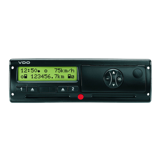
Product and system overview 1.2 Digital Tachograph DTCO 1381 Digital Tachograph DTCO 1381 1.2.1 DTCO 1381 Device description 12:50 0km/h 100436.8km Fig. 1 - 2: DTCO 1381 Front side Display Depending on the vehicle’s operational condition, different displays will appear, see chapter 3.2 "Display variations", page 3-5. - Page 24 (g) Release version (h) Part of the drawing reference number (10) Menu buttons Select desired function, acknowledge function or confirm actions, leave menu one step at a time or cancel the function. 1 - 8 © Siemens VDO Automotive AG Edition 07/2007...
-
Page 25: Dtco 1381 Rear Side
Product and system overview 1.2 Digital Tachograph DTCO 1381 1.2.2 DTCO 1381 Rear side Fig. 1 - 3: DTCO 1381 Rear side (11) Connection diagram Label with pin assignments and connection diagram (12) Seal for battery compartment Sealing against unauthorized opening of the battery com- partment (13) Battery compartment Buffer battery installed at factory... -
Page 26: Dtco 1381 Product Versions
/ none / positive orange / orange / positive green / none / positive green / green / positive Cover 0 standard (with Siemens VDO company logo) 1 without company logo 2 customer-specific company logo Housing 0 standard 1 with spacer... -
Page 27: Kitas 2171
Product and system overview 1.3 KITAS 2171 KITAS 2171 KITAS 2171 is part of the EC recording equipment, it provides real- time signals and cryptologically encoded data. The signals serve for recording the distance and speed. The DTCO 1381 can detect external interferences and influences by monitoring the data communication with the KITAS 2171 and com- paring this to the real-time signal. -
Page 28: Kitas 2171 Integrated Version
These KITAS versions are screwed into the gear output. A variety of lengths are available for the installation. KITAS 2171 Customer-specific version Fig. 1 - 6: KITAS 2171 Customer-specific version (example) Version KITAS 2171 Customer-specific version 2171.xx 1 - 12 © Siemens VDO Automotive AG Edition 07/2007... -
Page 29: Characteristics Of The Kitas 2171
The sensor cable must meet certain requirements, see chapter 2.2.6 "KITAS Sensor cable", page 2-19. The Siemens VDO standard sensor cables are available in a several different lengths, for example: 2.8 m, 8.5 m, or 15 m. Fig. 1 - 7:... -
Page 30: Tachograph Cards
If the authentication is positive, the following functions will be acti- vated: • Calibration • Test • Data download The DTCO 1381 can be activated only with a valid workshop card. 1 - 14 © Siemens VDO Automotive AG Edition 07/2007... - Page 31 Product and system overview 1.4 Tachograph cards Driver card The driver uses the driver card to identify himself to the DTCO 1381. (white) The card is used for normal driving and permits savings, displaying, or printing of activities under this identity. Company card The company card identifies a company, authorises access to the (yellow)
-
Page 32: Valid Combinations Of Tachograph Cards
No card Driver card – Control card – – – Workshop card – – – – Company card – – – = valid combination – = invalid combination ("cards conflict" event) 1 - 16 © Siemens VDO Automotive AG Edition 07/2007... -
Page 33: Chapter 2 Technical Data
Chapter 2 Technical data Edition 07/2007... - Page 34 KITAS 2171.0x Standard version ......2-16 2.2.4 KITAS 2171 Technical data ........ 2-17 2.2.5 Production date ..........2-18 2.2.6 KITAS Sensor cable ..........2-19 Connection diagram DTCO 1381 ......... 2-20 2 - 2 © Siemens VDO Automotive AG Edition 07/2007...
-
Page 35: Dtco 1381
Technical data 2.1 DTCO 1381 DTCO 1381 2.1.1 Installation dimensions and angle Installation dimensions Fig. 2 - 1: Installation dimensions of DTCO 1381 Permissible installation angle + 45° - 45° Fig. 2 - 2: Permissible installation angle of DTCO 1381 Installation angle of display Fig. -
Page 36: Pin Assignment
Term. W n-sensor signal input* CAN_H* CAN_GND* CAN_L* CAN_RES* Plug D Additional stylus, input 1* Additional stylus, input 2* TCO warning output v-pulse output* K-Line diagnosis interface* Info interface * Option 2 - 4 © Siemens VDO Automotive AG Edition 07/2007... -
Page 37: Connection Specifications
Technical data 2.1 DTCO 1381 2.1.3 Connection specifications Connection plug A (power supply, CAN bus) Function Parameter 12 V version 24 V version Comments min. typ. max. min. typ. max. Term. 30 Reference potential A5 Permanent Voltage [V] 10,5 voltage Short-time (max. - Page 38 Galvanic connection to pin A6 (optional capacitive con- nection) CAN_L Reference potential A7 Option Specification according to ISO 16844-6 (5) and ISO 11898 (6) 3) ADR variant: printer supply via pin A3 2 - 6 © Siemens VDO Automotive AG Edition 07/2007...
-
Page 39: Connection Plug B (Kitas 2171, Data Signals)
Technical data 2.1 DTCO 1381 Connection plug B (KITAS 2171, data signals) Function Parameter 12 V version 24 V version Comments min. typ. max. min. typ. max. v-sensor supply (+) Voltage [V] at I = 15 mA at I = 0 mA v-sensor connected to A5 supply (–) -
Page 40: Connection Plug C (N-System, Can Bus)
R = 120Ω connected to A4, C5 Option Specification according to ISO 16844-6 (5) and ISO 11898 (6) The symbol with current data in the "Comments" column indicates the direction of current. 2 - 8 © Siemens VDO Automotive AG Edition 07/2007... -
Page 41: Connection Plug D (Additional Stylus, Additional Functions)
Technical data 2.1 DTCO 1381 Connection plug D (additional stylus, additional functions) Function Parameter 12 V version 24 V version Comments min. typ. max. min. typ. max. Additional stylus Pulse width min. 100 ms input 1 at I = 0 mA at I = 1,7 mA High Additional stylus... -
Page 42: Pin Assignment Of Calibration And Download Interface
DTCO 1381 pin assignment of calibration and download interface Calibration interface Battery minus Data communication, K-Line Input/output signal calibration Battery plus (U - 3 V) Download interface Received data interface (RxD) Transmit data interface (TxD) 2 - 10 © Siemens VDO Automotive AG Edition 07/2007... -
Page 43: Technical Data
Technical data 2.1 DTCO 1381 2.1.5 Technical data Measurement range 0 ... 220 km/h 2 lines with 16 characters each, illuminated, dimmable* Installation angle of display ± 30° Character height 6.3 mm Operating voltage 24 V DC or 12 V DC* Power consumption 12 V DC* 24 V DC... -
Page 44: Production Date
M = Month of production January July February August March September April October November June M December YY= Year of production 04 2004 07 2007 05 2005 08 2008 06 2006 2 - 12 © Siemens VDO Automotive AG Edition 07/2007... -
Page 45: Printer Paper
Technical data 2.1 DTCO 1381 2.1.7 Printer paper Paper type Special paper approved for the DTCO 1381 Dimensions Diameter approx. 27,5 mm Width: approx. 56,5 mm Length: approx. 8 m Thickness: Ambient conditions -25 to 70 °C Order number 1381.90 03 03 00 Rear side of printer paper The test and approval marks are printed on the rear side of the printer paper. -
Page 46: Kitas 2171
Installation dimensions KITAS 2171.20 Integrated version Pin assignment Sensor supply (+) Sensor supply (–) Real time signal, v-sensor I/O data signal Fig. 2 - 9: Pin assignment KITAS 2171.20 Integrated version 2 - 14 © Siemens VDO Automotive AG Edition 07/2007... -
Page 47: Kitas 2171.50 Integrated Version
Technical data 2.2 KITAS 2171 2.2.2 KITAS 2171.50 Integrated version Installation dimensions KITAS 2171.50 35,2 90,2 115,2 33,8 88,8 113,8 64,8 64,8 64,8 Fig. 2 - 10: Installation dimensions KITAS 2171.50 Integrated version Pin assignment Sensor supply (+) Sensor supply (–) Real time signal, v-sensor I/O data signal Fig. -
Page 48: Kitas 2171.0X Standard Version
Fig. 2 - 12: Installation dimensions 2171.0x Standard version Pin assignment Sensor supply (+) Sensor supply (–) Real time signal, v-sensor I/O data signal Fig. 2 - 13: Pin assignment KITAS 2171.0x Standard version 2 - 16 © Siemens VDO Automotive AG Edition 07/2007... -
Page 49: Kitas 2171 Technical Data
Technical data 2.2 KITAS 2171 2.2.4 KITAS 2171 Technical data Integrated version Standard version 2171.20 xx 2171.50 xx 2171.0x Operational voltage U 6,5 ... 9 V DC 6,5 ... 9 V DC Power consumption max. 15 mA max. 15 mA Operating temperature Range A: -30 ... -
Page 50: Production Date
YY= Year of production 48 2004 51 2007 49 2005 52 2008 50 2006 M = Month of production January July February August March September April October November June M December 2 - 18 © Siemens VDO Automotive AG Edition 07/2007... -
Page 51: Kitas Sensor Cable
Technical data 2.2 KITAS 2171 2.2.6 KITAS Sensor cable Fig. 2 - 15: KITAS Sensor cable (1) Bayonet connection: DIN 72585-A1-4.1 • straight • 90 ° bend • with sealing eyebolts Protection type: DIN 40050 T9-IP69K (bayonet type connection) (2) Connection plug: AMP plug shell with Junior- (yellow) Power-Timer... -
Page 52: Connection Diagram Dtco 1381
2.3 Connection diagram DTCO 1381 Technical data Connection diagram DTCO 1381 Fig. 2 - 16: Connection diagram DTCO 1381 with KITAS 2171 and display instrument 2 - 20 © Siemens VDO Automotive AG Edition 07/2007... - Page 53 Chapter 3 Operating the DTCO 1381 Edition 07/2007...
- Page 54 Inserting workshop card ........3-16 Menu navigation after inserting workshop card ..........3-17 3.4.2 Removing workshop card ........3-20 Menu navigation after removing workshop card ..........3-20 Preparing for data download ........3-21 3 - 2 © Siemens VDO Automotive AG Edition 07/2007...
-
Page 55: General Instructions
Operating the DTCO 1381 3.1 General instructions General instructions 3.1.1 Handling the tachograph cards Attention! Possession of a tachograph card authorizes the holder to use the digital tachograph. The tachograph cards are person-specific (workshop cards are company-specific) and are therefore not trans- ferrable to others! An accredited workshop must securely retain, use, and administer its workshop card and PIN;... -
Page 56: Operating The Adr Variant
Retain the printouts where they will not be damaged by strong light, sunlight, moisture, or heat (making them illegible). Please obey your country's legal regulations surrounding the printouts, especially the obligation to preserve the printouts! 3 - 4 © Siemens VDO Automotive AG Edition 07/2007... -
Page 57: Display Variations
Operating the DTCO 1381 3.2 Display variations Display variations The display is a mixture of pictograms and text. 3.2.1 Selecting the text language The language will be determined by the tachograph card that is cur- rently inserted in card slot 1, the tachograph card that was most recently inserted, or the tachograph card with the higher value, such as the company card. -
Page 58: Display In Standby Mode
Explanation / meaning Operational notes If there is no tachograph card in card slot 1, this note will appear for approximately 20 seconds and then the standard display will appear. 3 - 6 © Siemens VDO Automotive AG Edition 07/2007... -
Page 59: Standard Display
Operating the DTCO 1381 3.2 Display variations 3.2.4 Standard display Menu display Explanation / meaning As soon as the vehicle starts moving, the standard display appears auto- matically. Time; the example shows local time Symbol of the displayed time with symbol ( ) = set local time without symbol ( ) = UTC time Mode;... -
Page 60: Selection Menu
Regardless of which display currently appears or whether the vehicle is moving or stationary, messages will be displayed with priority. Pictogram of the cause Text Memory code (position in error memory) ➥ Detailed information, see chapter 13 "Events and faults". 3 - 8 © Siemens VDO Automotive AG Edition 07/2007... -
Page 61: Special Displays
Operating the DTCO 1381 3.2 Display variations 3.2.7 Special displays Menu display Explanation / meaning Production status If the DTCO 1381 has not yet been activated to be an EC recording equipment, then the production status, symbol " " (1), will appear. The DTCO 1381 will not accept any tachograph cards except the workshop card. -
Page 62: Operational Notes As Information
The tachograph card has not yet been read completely. It is not possible to call up menu functions. These operational notes disappear automatically after three seconds. No steps must be taken. 3 - 10 © Siemens VDO Automotive AG Edition 07/2007... -
Page 63: Menu Functions
Operating the DTCO 1381 3.3 Menu functions Menu functions Please refer to the DTCO 1381 operating instructions for detailed information on the menu functions. 3.3.1 Setting the language As an alternative to the automatic language setting by the tacho- graph card, you can individually set a preferred language. Step / menu display Explanation / meaning –... -
Page 64: Retrieving Menu Functions
– Press the key Always follow the same procedure when making menu selections: – Select the desired menu function, such as printout driver 1, with the button – acknowledge with the button 3 - 12 © Siemens VDO Automotive AG Edition 07/2007... -
Page 65: Overview Of The Menu Structure
Operating the DTCO 1381 3.3 Menu functions 3.3.3 Overview of the menu structure Functions card slot 1 Functions card slot 2 Option only available in the production status or in calibration mode 3 - 13 Edition 07/2007 Technical Description DTCO 1381... -
Page 66: Menu Function "Service
After approx. one minute or pressing the button the DTCO 1381 returns to the menu "Service". Detailed information on the "Software-Upgrade" is contained in the Technical Description "Software-Upgrade DTCO 1381". 3 - 14 © Siemens VDO Automotive AG Edition 07/2007... -
Page 67: Leaving Menu Functions
Operating the DTCO 1381 3.3 Menu functions 3.3.5 Leaving menu functions Step / menu display Explanation / meaning – Press repetitively the button until the display "leave main menu" appears, – select " " with the button – acknowledge with the button –... -
Page 68: Calibration Mode
2. Eject any tachograph cards that may be already inserted. 3. Insert workshop card into card slot 1 with the chip facing up (after insertion, the card will be automatically locked mechani- cally). • The subsequent procedure is menu-guided. 3 - 16 © Siemens VDO Automotive AG Edition 07/2007... -
Page 69: Menu Navigation After Inserting Workshop Card
Operating the DTCO 1381 3.4 Calibration mode Menu navigation after inserting workshop card If the workshop card does not contain a preferred language or if the language is not available in the DTCO 1381, the text will appear in the language of the issuing member state, see chapter 3.2.1 "Selecting the text language", page 3-5. - Page 70 The beginning or end of the workday can be entered even without an inserted workshop card or at times other than during insertion or withdrawal of the card. 3 - 18 © Siemens VDO Automotive AG Edition 07/2007...
- Page 71 Operating the DTCO 1381 3.4 Calibration mode Step / menu display Explanation / meaning Continuation of reading the workshop card. The standard display appears; the DTCO 1381 still remains in opera- tional mode (2). The card symbol will be displayed only if the data of the driver card have been read completely.
-
Page 72: Removing Workshop Card
" " and – acknowledge with the button Continuation of data transfer to workshop card. The workshop card is released, the standard display and the opera- tional mode (1) appear. 3 - 20 © Siemens VDO Automotive AG Edition 07/2007... -
Page 73: Preparing For Data Download
For detailed information about the reading software, please refer to the appropriate documentation. For detailed information about a appropriate reading software, please refer to a Siemens VDO sales office or the traffic Ministry. 5. After downloading the data, make sure you always close the covering cap (1). - Page 74 3 - 22 © Siemens VDO Automotive AG Edition 07/2007...
-
Page 75: Chapter 4 Data Handling
Chapter 4 Data handling Edition 07/2007... - Page 76 Variable data .............4-20 4.3.3 Control card ............4-25 Fixed data ............4-25 Variable data .............4-26 4.3.4 Company card ...........4-27 Fixed data ............4-27 Variable data .............4-28 Data download ............4-29 Rights to access saved data .........4-30 4 - 2 © Siemens VDO Automotive AG Edition 07/2007...
-
Page 77: Chapter 4 Data Handling
Data handling 4.1 Data handling Data handling The DTCO 1381 registers in the internal data memory the activities and data of all drivers and the vehicle itself over a time period of at least 365 calendar days in accordance with CR (EEC) 3821/85, annex I B. -
Page 78: The Flow Of Data And Memory Behaviour
• Transfer of the updated data to the tachograph card and deletion of the data from the working memory (when requested by a tachograph card). 4 - 4 © Siemens VDO Automotive AG Edition 07/2007... -
Page 79: Buffer For V-Recording
Data handling 4.2 The flow of data and memory behaviour 4.2.2 Buffer for v-recording In two special cases, the buffer for v-recording will serve to store detailed speed data: • A large deceleration (a < -3 m/s ; such as hard braking, collision with an obstacle) –... -
Page 80: Contents Of The Data Memory
Recording control activities Identification of the DTCO Download procedures 1381 Recording of time adjust- Device calibrations Installation data ments Buffer for v-recording Fig. 4 - 2: Data in data memory, schematic diagram 4 - 6 © Siemens VDO Automotive AG Edition 07/2007... -
Page 81: Data Saved In The Data Memory
Data handling 4.2 The flow of data and memory behaviour 4.2.4 Data saved in the data memory The DTCO 1381 registers and saves the following legally stipulated data: Identification data of the • Name of manufacturer DTCO 1381 • Address of manufacturer •... - Page 82 365 days. Odometer At time 00:00 on every calendar day the following data will be regis- tered and saved: • Odometer reading • Date 4 - 8 © Siemens VDO Automotive AG Edition 07/2007...
- Page 83 Data handling 4.2 The flow of data and memory behaviour Detailed speed The following data will be registered and saved every second for the last 24 hours of driving time: • Momentary speed in km/h • Date and time Speed / rpm profiles After any use of the vehicle (from insertion to removal of the driver card), the DTCO 1381 assesses driven profiles.
- Page 84 Number of the same types of events on this day. Note This data can be recorded only after re- establishing the power supply, whereby the accuracy here can be one minute. 4 - 10 © Siemens VDO Automotive AG Edition 07/2007...
- Page 85 Data handling 4.2 The flow of data and memory behaviour Faults (errors) The DTCO 1381 saves faults (errors) with a resolution of one second. The following data will be saved for every fault (error): Fault Saving regulations Recorded data Card faults •...
- Page 86 – Display, printing, or downloading of data from memory – Display, printing, or downloading of card data With a download, the time period (from/to) of the copied data is reg- istered. 4 - 12 © Siemens VDO Automotive AG Edition 07/2007...
- Page 87 Data handling 4.2 The flow of data and memory behaviour Company locking data The following information is registered and saved from the last 20 company locking actions: • Lock-in – date and time • Lock-out – date and time • Number of the company card, issuing member state •...
-
Page 88: Tachograph Cards
Last name, first name (cardholder identification) • Date of birth • Preferred language • Driver’s license number • Issuing member state, name of the issuing authority / insti- tution, date of issuance 4 - 14 © Siemens VDO Automotive AG Edition 07/2007... -
Page 89: Variable Data
Data handling 4.3 Tachograph cards Variable data Data on vehicles used The data about the vehicles used is saved by calendar day and time period of usage: • Vehicle registration number, registering authority of member state • Date, time, and odometer the first time the vehicle is used or the first time the card is inserted, respectively. - Page 90 When special conditions are entered (manual entry by the driver), the following data is also saved: • Type of entry • Date and time At least 56 entries will be saved. 4 - 16 © Siemens VDO Automotive AG Edition 07/2007...
- Page 91 Data handling 4.3 Tachograph cards Events The following events are saved on the driver card: • Power interruption • Error in communication with the KITAS 2171 • Attempt to breach security • Time overlap* • Card insertion while driving* • Last card procedure not completely correctly* * This event will be saved only when the event was caused by the inserted driver card.
- Page 92 The card data download can be saved on the tachograph card only if this happens through the DTCO 1381. In other words, the card must be located in a card slot on the DTCO 1381. 4 - 18 © Siemens VDO Automotive AG Edition 07/2007...
-
Page 93: Workshop Card
Data handling 4.3 Tachograph cards 4.3.2 Workshop card All of the workshop-based data (fixed and variable) defined in CR (EEC)) 3821/85, annex I B is saved on the workshop card. An approved recording equipment manufacturer, vehicle manufac- turer, installer, or a workshop uses its card to identify itself to the DTCO 1381, enabling saving of activities under this identity. -
Page 94: Variable Data
Driving status (single or crew) • Insertion location of the card (slot 1 or 2) • Card status (inserted or not inserted) • Activity (time group) • Time of the change 4 - 20 © Siemens VDO Automotive AG Edition 07/2007... - Page 95 Data handling 4.3 Tachograph cards Location at the beginning and When the location at the beginning and end of the work time is end of the working time entered (manual entry), the following data is saved: • Date and time •...
- Page 96 • Place of registration of the vehicle, in which the event appeared The three most recent events of all types will be saved; in total, 18 entries will be saved. 4 - 22 © Siemens VDO Automotive AG Edition 07/2007...
- Page 97 Data handling 4.3 Tachograph cards Faults (errors) The following faults are saved on the workshop card: • Faults of the DTCO 1381 • Card fault if the workshop card is the object of the fault The following data will be saved about faults: •...
- Page 98 – Tire size – Legally permitted maximum speed – Odometer – old value – Odometer – new value – Date and time – old value – Date and time – new value 4 - 24 © Siemens VDO Automotive AG Edition 07/2007...
-
Page 99: Control Card
Data handling 4.3 Tachograph cards 4.3.3 Control card All of the control authority-based data (fixed and variable) defined in CR (EEC) 3821/85, annex I B is saved on the control card. An employee of an control authority uses the card to identify himself to the DTCO 1381, enabling saving of control activities under this identity. -
Page 100: Variable Data
Vehicle registration number • The vehicle’s place of registration • In the case of a driver card control – Card number – Issuing member state At least 230 entries will be saved. 4 - 26 © Siemens VDO Automotive AG Edition 07/2007... -
Page 101: Company Card
Data handling 4.3 Tachograph cards 4.3.4 Company card All of the company-based data (fixed and variable data about the owner or holder of the vehicle) defined in CR (EEC) 3821/85, annex I B is saved on the company card. The company representative uses the card to identify himself to the DTCO 1381, enabling saving of company activities under this identity. -
Page 102: Variable Data
In the case of card data downloading, number and issuing member state of the driver card • Vehicle registration number and registration authority of the vehicle in which a download was executed At least 230 entries will be saved. 4 - 28 © Siemens VDO Automotive AG Edition 07/2007... -
Page 103: Data Download
Data handling 4.4 Data download Data download Driver, vehicle, and calibration data can be downloaded (copied) over the download interface from the DTCO 1381 data memory and from an inserted driver card. The legislators have planned a data download for the following cases: •... -
Page 104: Rights To Access Saved Data
T1 = Driver activities of the last eight days without driver identi- fication data T2 = Driver identification only for the inserted card T3 = The associated company’s driver activities = No right to access data 4 - 30 © Siemens VDO Automotive AG Edition 07/2007... -
Page 105: Chapter 5 Installation
Chapter 5 Installation Edition 07/2007... - Page 106 Connection plug B ..........5-28 Connection plugs C and D ......... 5-29 Connection plug A ..........5-30 5.5.8 Mounting the DTCO 1381 ......... 5-31 Removing the DTCO 1381 ......... 5-32 5 - 2 © Siemens VDO Automotive AG Edition 07/2007...
-
Page 107: General Instructions
Installation 5.1 General instructions General instructions 5.1.1 Terminology definitions Installation of the DTCO 1381 is divided into the following steps: 1. Installation Mechanical and electrical installation of the DTCO 1381 compo- nents into the vehicle. 2. Preprogramming Preprogramming of all known or operationally necessary and legally required parameters. -
Page 108: Personnel Prerequisites
The equipment and tools required or recommended by the man- ufacturer must be available. • The equipment, testing devices, and furnishings must comply with the respective valid legal requirements for the country in which they are used. 5 - 4 © Siemens VDO Automotive AG Edition 07/2007... -
Page 109: Other Instructions
Installation 5.1 General instructions 5.1.4 Other instructions Proper use The DTCO 1381 is an EC recording equipment that complies with CR (EEC) 3821/85, annex I B for the registration, saving, display, printing, and outputting of driver-based and vehicle-based data. It may be used only for the purpose for which it is designed. -
Page 110: Handling The Tachograph Cards
Do not place it in direct proximity to strong electromagnetic fields. • Do not use the card beyond its period of validity. Apply for a new card in a timely manner before expiry. 5 - 6 © Siemens VDO Automotive AG Edition 07/2007... -
Page 111: Instructions On Installing The Dtco 1381
Installation 5.2 Instructions on installing the DTCO 1381 Instructions on installing the DTCO 1381 This chapter describes the correct installation of the DTCO 1381 components in the vehicle. Attention! Vehicles used for the carriage of dangerous goods During installation of the DTCO 1381 (ADR variant) in a vehicle for the carriage of dangerous goods it is essential to observe all addi- tional or different instructions, requirements, and work steps in chapter 6 "Installation of the ADR variant". -
Page 112: General Installation Instructions
When separating plug-in connections, do not pull on the cable, but rather on the plugs or the proper unlocking systems only. • For mounting tasks, use only original Siemens VDO Automotive installation parts and accessories. Install undamaged compo- nents only. -
Page 113: Working On The Electrical Onboard Power Supply
Installation 5.2 Instructions on installing the DTCO 1381 5.2.2 Working on the electrical onboard power supply Caution! Danger of short circuits Before working on the onboard power supply, please observe the relevant manufacturer's instructions! • Although disconnection of the vehicle’s battery will prevent short circuits, this may also result in other secondary effects: –... -
Page 114: Lead Sealing The Dtco 1381 Components
Observe the following notes when sealing the DTCO 1381 compo- nents: • When sealing, use only original tools from Siemens VDO Auto- motive and the sealing parts available as accessories. • The components can be lead-sealed during the individual oper- ating steps. -
Page 115: Preparing Sealing Tools
Installation 5.2 Instructions on installing the DTCO 1381 Preparing sealing tools Assembling the sealing tool To emboss the seal caps properly, equip and adjust the sealing pliers accordingly. 1. Insert an original Kienzle sealing insert (1) into the pliers and engage it using the locking screw (1a). -
Page 116: Criteria For The Installation Site
If installed remotely, the warning message must be labeled with a " " symbol and be shown in the color "amber" or "orange". 5.3.2 Manufacturer’s specifications Installation dimensions of DTCO 1381 Fig. 5 - 1: Installation dimensions of DTCO 1381 5 - 12 © Siemens VDO Automotive AG Edition 07/2007... - Page 117 Installation 5.3 Criteria for the installation site Installation angle of the DTCO 1381 + 45° - 45° Fig. 5 - 2: Installation angle of the DTCO 1381 Clearance for the installation and operation of the DTCO 1381 Fig. 5 - 3: Clearance for the installation and operation of the DTCO 1381 5 - 13 Edition 07/2007...
-
Page 118: Manufacturer's Recommendations
Fig. 5 - 5: Support at the rear of the radio compartment Support of the housing rear side of the DTCO 1381 at the suitable mounting in the radio compartment. 5 - 14 © Siemens VDO Automotive AG Edition 07/2007... -
Page 119: Tools And Installation Accessories
Installation 5.4 Tools and installation accessories Tools and installation accessories 5.4.1 Tools Fig. 5 - 6: Tools Special tools Seal crimpers Mounting tool for lead seals Removing aids (bracket) for removing of the DTCO 1381 from the installation frame (2 pieces) Special tools for disengaging the Junior-Power-Timer Standard tools You may need a standard automotive mechanic’s tool set for... -
Page 120: Installation Accessories
2170.80 01 08 50 Pulse cable (8.5 m or as appropriate) 1999.92 00 00 12 Seal wire 1999.92 00 00 15 Two-hole seal 2170.92 00 00 03 KITAS hexagonal seal 5 - 16 © Siemens VDO Automotive AG Edition 07/2007... -
Page 121: Performing The Installation
Installation 5.5 Performing the installation Performing the installation Definition Mechanical and electrical installation of the DTCO 1381 components into the vehicle. Requirements The description of installation assumes the following: • The place where the DTCO 1381 is installed meets all legal stipu- lations. -
Page 122: Checking The Condition Of The Dtco 1381 Upon Delivery
(display vehicle "technical data") the data stored in the DTCO 1381. Attention! If any of the above-mentioned points do not match the specifica- tions, do not install the DTCO 1381! 5 - 18 © Siemens VDO Automotive AG Edition 07/2007... -
Page 123: Checking The Buffer Battery
Installation 5.5 Performing the installation Checking the buffer battery The buffer battery must be replaced in the following cases to ensure reliable function of the DTCO 1381: • During installation, activation or initial calibration if the pro- duction date of the DTCO 1381 is more than 12 months ago. •... -
Page 124: Checking The Place Of Installation And The Cable Connections
Junior-Power-Timer. Caution! Danger of fire due to short circuit Damaged cables can cause short circuits, undesired interferences, or disturbances. Please replace damaged cables immediately! 5 - 20 © Siemens VDO Automotive AG Edition 07/2007... - Page 125 Installation 5.5 Performing the installation Manufacturer recommendations Fig. 5 - 8: Manufacturer recommendations • Make sure that the connection lines (1) are sufficiently long that an installed DTCO 1381 can be easily removed from its com- partment and additional connections can be realised as nec- essary.
-
Page 126: Installing The Kitas 2171
1. Screw in the KITAS 2171 – integrated version (2a) – into the transmission output (1). Screw the KITAS 2171 – standard version (2b) – onto the trans- mission output (1). Attention! Observe the maximum tightening torque (50 Nm). 5 - 22 © Siemens VDO Automotive AG Edition 07/2007... -
Page 127: Sealing The Kitas 2171 To The Transmission
Installation 5.5 Performing the installation 5.5.5 Sealing the KITAS 2171 to the transmission With sealing wire The following description describes the procedure for using the KITAS 2171 in the integrated, screw-in version. In the case of the other methods of installation, the procedure is identical. Fig. -
Page 128: With Kitas Hexagonal Seal
4. Connect the KITAS sensor cable (3) to the KITAS 2171 via the bayonet-type connection. Observe the instructions on sealing, see chapter 5.2.4 "Lead sealing the DTCO 1381 components", page 5-10. 5 - 24 © Siemens VDO Automotive AG Edition 07/2007... -
Page 129: Preparing The Radio Compartment
Installation 5.5 Performing the installation 5.5.6 Preparing the radio compartment Assembling installation frame in the radio compartment Fig. 5 - 12: Assembling installation frame in the radio compartment 1. Insert the installation frame (1). 2. Use a screwdriver to bend up cut-outs (2) with a screwdriver and hook them onto the dashboard so that the installation frame is sitting firmly in the radio compartment. -
Page 130: Checking The Radio Compartment With The Installation Frame
1. Check whether the spacer (1) is necessary for support at the rear of the compartment. 2. If necessary, screw the spacer to the rear of the housing of the DTCO 1381. 5 - 26 © Siemens VDO Automotive AG Edition 07/2007... -
Page 131: Connecting The Dtco 1381 To The Vehicle's Onboard Power Supply
Installation 5.5 Performing the installation 5.5.7 Connecting the DTCO 1381 to the vehicle’s onboard power supply Follow the following procedure in the proper order to connect the DTCO 1381 to the vehicle’s onboard power supply: 1. Connection plug B (motion sensor KITAS 2171, v-outputs). 2. -
Page 132: Connection Plug B
1. Insert the yellow plug (1) of the KITAS sensor cable into the con- nection plug "B" on the DTCO 1381. The KITAS sensor cable must meet special requirements, see chapter 2.2.6 "KITAS Sensor cable", page 2-19. 5 - 28 © Siemens VDO Automotive AG Edition 07/2007... -
Page 133: Connection Plugs C And D
Installation 5.5 Performing the installation Connection plugs C and D The pin assignments and connection diagram may vary depending on the version of the DTCO 1381. Fig. 5 - 16: Connect the DTCO 1381 connection plugs C and D 1. Insert the red plug (1) into connection plug "C" and the brown plug (2) into connection plug "D"... -
Page 134: Connection Plug A
Interrupt the respective power circuit by removing the fuse. 2. Then insert the white plug (1) into the connection plug "A" on the DTCO 1381. 3. Reconnect vehicle battery. Re-insert the fuses. 5 - 30 © Siemens VDO Automotive AG Edition 07/2007... -
Page 135: Mounting The Dtco 1381
Installation 5.5 Performing the installation 5.5.8 Mounting the DTCO 1381 Fig. 5 - 18: Mounting the DTCO 1381 in the radio compartment 1. On the rear of the DTCO 1381 (2) press the mounting cap (5) onto the spacer (3) or the threaded bolt (4). 2. -
Page 136: Removing The Dtco 1381
1. Feed the removal aids (1) into the openings on both outer sides of the DTCO 1381 until the engagement springs release. 2. Then press the removal aids lightly to the outside and pull the DTCO 1381 from the radio compartment. 5 - 32 © Siemens VDO Automotive AG Edition 07/2007... - Page 137 Chapter 6 Installation of the ADR variant Edition 07/2007...
- Page 138 Power supply DTCO 1381 (ADR variant) ....6-9 6.2.3 KITAS 2171 intrinsically safe circuitry ....6-10 DTCO 1381 (ADR variant) EC type-examination certificate ......... 6-11 KITAS 2171 EC type-examination certificate ....6-15 6 - 2 © Siemens VDO Automotive AG Edition 07/2007...
-
Page 139: Dtco 1381 In Vehicles Used For The Carriage Of Hazardous Goods
Installation of the ADR variant 6.1 DTCO 1381 in vehicles used for the carriage of hazardous goods DTCO 1381 in vehicles used for the carriage of hazardous goods This chapter describes – supplementary to Chapter 5 "Installation" – only the additional or different instructions, requirements, and work steps for correct installation of the DTCO 1381 components in a vehicle for the carriage of dangerous goods. -
Page 140: Tachograph System Requirements
EN 50020, intrinsic safety "ib" as an associated intrinsically-safe device. EC type-approval certificate For the KITAS 2171, an EC type-approval certificate was issued KITAS 2171 according to EN 50020, intrinsic safety "ib", as an intrinsically-safe device. 6 - 4 © Siemens VDO Automotive AG Edition 07/2007... -
Page 141: Requirements For The Connection Of External Devices
Installation of the ADR variant 6.1 DTCO 1381 in vehicles used for the carriage of hazardous goods 6.1.3 Requirements for the connection of external devices The connection of external devices to the interfaces (download-, remote- or info interface pin D8) of the DTCO 1381 is permissible only when these devices fulfil the following requirements: •... -
Page 142: Identification Of The Tachograph System
(ADR variant) Fig. 6 - 3: Model plate DTCO 1381 (ADR variant) Model designation: DTCO 1381.xxx Approval mark: TÜV 03 ATEX 2324X II 3(2)G EEx nA [Ib] IIC T6 0032 6 - 6 © Siemens VDO Automotive AG Edition 07/2007... -
Page 143: Kitas 2171 Pulse Generator
KITAS 2171 pulse generator EMC type approval e1-033434 EEC design approval e1-175 Manufacturer: Siemens VDO Automotive AG Villingen Approval mark: II2G EEx ib IIC T4 0032 TÜV 02 ATEX 1842X KITAS model designation, production date: 2171.xx xxxx YYM / 2171.xx xxxx YYM... -
Page 144: Performing The Installation
Only authorized repair centers may perform repairs to the DTCO 1381 and the KITAS 2171! Never attempt to open or make changes to the DTCO 1381 and the KITAS 2171. 6 - 8 © Siemens VDO Automotive AG Edition 07/2007... -
Page 145: Power Supply Dtco 1381 (Adr Variant)
Installation of the ADR variant 6.2 Performing the installation 6.2.2 Power supply DTCO 1381 (ADR variant) Fig. 6 - 5: Power supply attachment diagram DTCO 1381 (ADR variant) 1. Separate the vehicle’s battery from the on-board power supply Interrupt the respective power circuit by removing the fuse. 2. -
Page 146: Kitas 2171 Intrinsically Safe Circuitry
Fig. 6 - 6: KITAS 2171 intrinsically safe circuitry 1. Insert the yellow plug (1) of the KITAS sensor cable into the con- nection plug "B" on the DTCO 1381. 6 - 10 © Siemens VDO Automotive AG Edition 07/2007... -
Page 147: Dtco 1381 (Adr Variant) Ec Type-Examination Certificate
Installation of the ADR variant 6.3 DTCO 1381 (ADR variant) EC type-examination certificate DTCO 1381 (ADR variant) EC type-examination certificate Fig. 6 - 7: DTCO 1381 (ADR variant) EC type-examination certificate, page 1 6 - 11 Edition 07/2007 Technical Description DTCO 1381... - Page 148 6.3 DTCO 1381 (ADR variant) EC type-examination certificate Installation of the ADR variant Fig. 6 - 8: DTCO 1381 (ADR variant) EC type-examination certificate, page 2 6 - 12 © Siemens VDO Automotive AG Edition 07/2007...
- Page 149 Installation of the ADR variant 6.3 DTCO 1381 (ADR variant) EC type-examination certificate Fig. 6 - 9: DTCO 1381 (ADR variant) EC type-examination certificate, page 3 6 - 13 Edition 07/2007 Technical Description DTCO 1381...
- Page 150 6.3 DTCO 1381 (ADR variant) EC type-examination certificate Installation of the ADR variant Fig. 6 - 10: DTCO 1381 (ADR variant) EC type-examination certificate, page 4 6 - 14 © Siemens VDO Automotive AG Edition 07/2007...
-
Page 151: Kitas 2171 Ec Type-Examination Certificate
Installation of the ADR variant 6.4 KITAS 2171 EC type-examination certificate KITAS 2171 EC type-examination certificate Fig. 6 - 11: KITAS 2171 EC type-examination certificate 6 - 15 Edition 07/2007 Technical Description DTCO 1381... - Page 152 6 - 16 © Siemens VDO Automotive AG Edition 07/2007...
- Page 153 Chapter 7 Preprogramming Edition 07/2007...
- Page 154 Testing equipment ............7-4 Performing the preprogramming ......... 7-5 7.3.1 Legally stipulated parameters ......7-5 7.3.2 Device-specific parameters ........7-6 7.3.3 Other parameters ..........7-6 7.3.4 Entering parameters ........... 7-7 7 - 2 © Siemens VDO Automotive AG Edition 07/2007...
-
Page 155: General Instructions
Preprogramming 7.1 General instructions General instructions Installation of the DTCO 1381 is divided into the following steps: 1. Installation Mechanical and electrical installation of the DTCO 1381 compo- nents into the vehicle. 2. Preprogramming Preprogramming of all known or operationally necessary and legally required parameters. -
Page 156: Testing Equipment
MTC 1602.04 or ATC 1601.26. Fig. 7 - 1: Siemens VDO SDS test devices MTC 1602.04 / ATC 1601.26 For the preprogramming with the Siemens VDO SDS test devices the following testing equipment must be available: BTC test software, version DTCO 1381 or higher... -
Page 157: Performing The Preprogramming
Preprogramming 7.3 Performing the preprogramming Performing the preprogramming Definition Preprogramming of all known or operationally necessary and legally required parameters. Attention! During preprogramming, be absolutely certain that the DTCO 1381 is operated in the specified voltage range! 7.3.1 Legally stipulated parameters The following parameters are legally stipulated and must be prepro- grammed: •... -
Page 158: Device-Specific Parameters
The settings for the device-specific parameters are dependent on the customer or device type. 7.3.3 Other parameters Other parameters can be preprogrammed if necessary: • Installation date • Date of the next calibration • etc. 7 - 6 © Siemens VDO Automotive AG Edition 07/2007... -
Page 159: Entering Parameters
Preprogramming 7.3 Performing the preprogramming 7.3.4 Entering parameters Please refer to the test device instructions for information on how to enter the calibration parameters. Legally stipulated parameters The following parameters are legally stipulated and must be pro- grammed: • Vehicle identification number •... - Page 160 Other parameters can be preprogrammed if necessary: • Installation date • Date of the next calibration • etc. Attention! Check whether the programmed and saved parameters are according to the beforehand measured parameters. 7 - 8 © Siemens VDO Automotive AG Edition 07/2007...
-
Page 161: Chapter 8 Installation And Functional Test
Chapter 8 Installation and functional test Edition 07/2007... - Page 162 Chapter 8 Installation and functional test General instructions ............. 8-3 8.1.1 Installation and functional test ......8-4 Permissible error limits ..........8-5 8.2.1 Creating and sealing installation plate ....8-6 8 - 2 © Siemens VDO Automotive AG Edition 07/2007...
-
Page 163: General Instructions
Installation and functional test 8.1 General instructions General instructions Installation of the DTCO 1381 is divided into the following steps: 1. Installation Mechanical and electrical installation of the DTCO 1381 compo- nents into the vehicle. 2. Preprogramming Preprogramming of all known or operationally necessary and legally required parameters. -
Page 164: Installation And Functional Test
On a DTCO 1381 that is not yet activated, the compliance with the specified error limits can be performed only visually. 8 - 4 © Siemens VDO Automotive AG Edition 07/2007... -
Page 165: Permissible Error Limits
Installation and functional test 8.2 Permissible error limits Permissible error limits Distance Permissible error limit of the distance measurement (on a distance of at least 1000 m): • ± 1 % before installation • ± 2 % during installation and during the regularly inspections •... -
Page 166: Creating And Sealing Installation Plate
The installation plate must be replaced after every intervention into the system. * The name and address or company logo of the workshop or the manufacturer may be printed on the sealing foil. 8 - 6 © Siemens VDO Automotive AG Edition 07/2007... -
Page 167: Chapter 9 Activation
Chapter 9 Activation Edition 07/2007... - Page 168 Performing the activation ..........9-8 9.3.1 Inserting workshop card ........9-8 Menu navigation after inserting workshop card ............ 9-9 9.3.2 Removing workshop card ........9-11 Menu navigation after removing workshop card ..........9-11 9 - 2 © Siemens VDO Automotive AG Edition 07/2007...
-
Page 169: General Instructions
Activation 9.1 General instructions General instructions 9.1.1 Terminology definitions Installation of the DTCO 1381 is divided into the following steps: 1. Installation Mechanical and electrical installation of the DTCO 1381 compo- nents into the vehicle. 2. Preprogramming Preprogramming of all known or operationally necessary and legally required parameters. -
Page 170: Personnel Prerequisites
PIN must be entered, and the workshop card must be posi- tively authenticated. Note the legal provisions applicable in your country and check when and how the DTCO 1381 must be activated. 9 - 4 © Siemens VDO Automotive AG Edition 07/2007... -
Page 171: Pairing With The Kitas 2171
Activation 9.1 General instructions 9.1.4 Pairing with the KITAS 2171 • The DTCO 1381 and the KITAS 2171 are paired together auto- matically during activation (the first time a workshop card is inserted). • During the pairing process, the DTCO 1381 and the KITAS 2171 mutually authenticate each other and create a shared work key. -
Page 172: Handling The Tachograph Cards
Do not place it in direct proximity to strong electromagnetic fields. • Do not use the card beyond its period of validity. Apply for a new card in a timely manner before expiry. 9 - 6 © Siemens VDO Automotive AG Edition 07/2007... -
Page 173: Checking The Buffer Battery
Activation 9.2 Checking the buffer battery Checking the buffer battery The buffer battery must be replaced in the following cases to ensure reliable function of the DTCO 1381: • During installation, activation or initial calibration if the pro- duction date of the DTCO 1381 is more than 12 months ago. •... -
Page 174: Performing The Activation
1. Switch ignition on (required only for ADR variant). 2. Insert workshop card into card slot 1 with the chip facing up (after insertion, the card will be automatically locked mechani- cally). • The subsequent procedure is menu-guided. 9 - 8 © Siemens VDO Automotive AG Edition 07/2007... -
Page 175: Menu Navigation After Inserting Workshop Card
Activation 9.3 Performing the activation Menu navigation after inserting workshop card If the workshop card does not contain a preferred language or if the language is not available in the DTCO 1381, the text will appear in the language of the issuing member state, see chapter 3.2.1 "Selecting the text language", page 3-5. - Page 176 During activation, the DTCO 1381 resets the odometer reading to the value "0.0 km". After reading the workshop card the standard display appears, the DTCO 1381 is now in calibration mode " ". 9 - 10 © Siemens VDO Automotive AG Edition 07/2007...
-
Page 177: Removing Workshop Card
Activation 9.3 Performing the activation 9.3.2 Removing workshop card 1. Press the ejection button of the card slot in which the workshop card is located. • The subsequent procedure is menu-guided. 2. After the card has been released (mechanical unlocking of the card), remove the workshop card from the card slot. - Page 178 9.3 Performing the activation Activation Step / menu display Explanation / meaning The workshop card is released, the standard display and the opera- tional mode (1) appear. 9 - 12 © Siemens VDO Automotive AG Edition 07/2007...
-
Page 179: Chapter 10 First Calibration
Chapter 10 First calibration Edition 07/2007... - Page 180 10.5.4 Other parameters ........... 10-18 10.5.5 Entering parameters ........10-18 10.5.6 Removing workshop card ........ 10-20 Menu navigation after removing workshop card ..........10-20 10.5.7 Creating and sealing installation plate ..... 10-21 10 - 2 © Siemens VDO Automotive AG Edition 07/2007...
-
Page 181: General Instructions
First calibration 10.1 General instructions 10.1 General instructions 10.1.1 Terminology definitions Installation of the DTCO 1381 is divided into the following steps: 1. Installation Mechanical and electrical installation of the DTCO 1381 compo- nents into the vehicle. 2. Preprogramming Preprogramming of all known or operationally necessary and legally required parameters. -
Page 182: Personnel Prerequisites
The equipment and tools required or recommended by the man- ufacturer must be available. • The equipment, testing devices, and furnishings must comply with the respective valid legal requirements for the country in which they are used. 10 - 4 © Siemens VDO Automotive AG Edition 07/2007... -
Page 183: Handling The Tachograph Cards
First calibration 10.1 General instructions 10.1.4 Handling the tachograph cards Attention! Possession of a tachograph card authorizes the holder to use the digital tachograph. The tachograph cards are person-specific (workshop cards are company-specific) and are therefore not trans- ferrable to others! An accredited workshop must securely retain, use, and administer its workshop card and PIN;... -
Page 184: Calibration Instructions
The accredited workshop must guarantee that the calibration is per- formed only via one interface selected before and that the cali- bration functions of the other interfaces are deactivated. 10 - 6 © Siemens VDO Automotive AG Edition 07/2007... -
Page 185: Programming The Utc Time
First calibration 10.2 Calibration instructions 10.2.3 Programming the UTC time Before activating the DTCO 1381 as the EU control device, unre- stricted programming of the UTC time is possible. After activation of the DTCO 1381 and one-off programming of the UTC time, this function is blocked for security reasons. -
Page 186: Checking The Kitas 2171 And The Kitas Sensor Cable
10. Separate the test connection and reconnect the original KITAS sensor cable with DTCO 1381 and KITAS 2171. 11. Connect the DTCO 1381 to the supply voltage. 12. Remove the workshop card. 10 - 8 © Siemens VDO Automotive AG Edition 07/2007... -
Page 187: Pairing With The Kitas 2171
First calibration 10.2 Calibration instructions 10.2.6 Pairing with the KITAS 2171 • The DTCO 1381 and the KITAS 2171 are paired together auto- matically during activation (the first time a workshop card is inserted). • During the pairing process, the DTCO 1381 and the KITAS 2171 mutually authenticate each other and create a shared work key. -
Page 188: Testing Equipment
Siemens VDO SDS test devices MTC 1602.04 or ATC 1601.26. Fig. 10 - 1: Siemens VDO SDS test devices MTC 1602.04 / ATC 1601.26 For the calibration with the Siemens VDO SDS test devices the fol- lowing testing equipment must be available:... -
Page 189: Checking The Buffer Battery
First calibration 10.4 Checking the buffer battery 10.4 Checking the buffer battery The buffer battery must be replaced in the following cases to ensure reliable function of the DTCO 1381: • During installation, activation or initial calibration if the pro- duction date of the DTCO 1381 is more than 12 months ago. -
Page 190: Performing The First Calibration
EC recording equipment are prescribed within the first cali- bration. It is possible to access the calibration functions through the cali- bration interface, the CAN bus diagnosis, or the K-Line diagnosis without a workshop card. 10 - 12 © Siemens VDO Automotive AG Edition 07/2007... -
Page 191: Inserting Workshop Card
First calibration 10.5 Performing the first calibration Attention! If the workshop determines with the inspection – according to CR (EEC) 3821/85, annex I B, paragraph IV – that the housing switch was operated or is, the law-conformal functioning of the DTCO 1381 must be proven by appropriate inspections. -
Page 192: Menu Navigation After Inserting Workshop Card
– use the button to select the desired character or number of characters and – acknowledge with the button 10 - 14 © Siemens VDO Automotive AG Edition 07/2007... - Page 193 First calibration 10.5 Performing the first calibration Step / menu display Explanation / meaning If incorrect PIN entered – Acknowledge message with the button and re-enter the number. Cancel PIN entry – Press the ejection button of the card slot in which the workshop card is located.
- Page 194 • Calling up menu functions. • Requesting a tachograph card. After the card has been read, the DTCO 1381 switches to the cali- bration mode (3). 10 - 16 © Siemens VDO Automotive AG Edition 07/2007...
-
Page 195: Legally Stipulated Parameters
First calibration 10.5 Performing the first calibration 10.5.2 Legally stipulated parameters The following parameters are legally stipulated and must be updated or acknowledged: • Vehicle identification number • Vehicle registration number • Country of registration • Characteristic coefficient (w-value) • Recording equipment constant (k-value)* •... -
Page 196: Other Parameters
(2, 3) when the workshop card is removed. Via the menu functions you can print (printout vehicle "technical data") or display (display vehicle "technical data") the calibration date and the purpose for the calibration. 10 - 18 © Siemens VDO Automotive AG Edition 07/2007... - Page 197 First calibration 10.5 Performing the first calibration Device-specific parameters Depending on the variation of the DTCO 1381, other parameters that are not legally-stipulated must be updated or acknowledged: • n-constant • Drive shaft I/U • etc. Other parameter Other parameters can be updated or acknowledged if necessary: •...
-
Page 198: Removing Workshop Card
" " and – acknowledge with the button Continuation of data transfer to workshop card. The workshop card is released, the standard display and the opera- tional mode (1) appear. 10 - 20 © Siemens VDO Automotive AG Edition 07/2007... -
Page 199: Creating And Sealing Installation Plate
First calibration 10.5 Performing the first calibration 10.5.7 Creating and sealing installation plate After the first calibration, the installation plate must be attached on, in, or directly next to the recording equipment where it will be easily visible. 1. The following information must be transferred to the instal- lation plate: •... - Page 200 10 - 22 © Siemens VDO Automotive AG Edition 07/2007...
-
Page 201: Chapter 11 Regularly Inspection
Chapter 11 Regularly inspection Edition 07/2007... - Page 202 11.5.4 Other parameters ........... 11-18 11.5.5 Entering parameters ........11-18 11.5.6 Removing workshop card ........ 11-20 Menu navigation after removing workshop card ..........11-20 11.5.7 Creating and sealing installation plate ..... 11-21 11 - 2 © Siemens VDO Automotive AG Edition 07/2007...
-
Page 203: General Instructions
Regularly inspection 11.1 General instructions 11.1 General instructions 11.1.1 Personnel prerequisites In the following instructions, the manufacturer assumes that the personnel possess extensive professional knowledge, securely master the necessary technical activities, and have been trained in the use of the DTCO 1381 components as appropriate for the area of application. -
Page 204: Handling The Tachograph Cards
Do not place it in direct proximity to strong electromagnetic fields. • Do not use the card beyond its period of validity. Apply for a new card in a timely manner before expiry. 11 - 4 © Siemens VDO Automotive AG Edition 07/2007... -
Page 205: Calibration Instructions
Regularly inspection 11.2 Calibration instructions 11.2 Calibration instructions The CR (EEC) 3821/85, annex I B, defines the criteria for the cali- bration of EC recording equipment. Note the legal provisions applicable in your country and check, how the calibration must be performed and whether further tests of the EC recording equipment are prescribed. -
Page 206: Parameter Measurements
4. Check whether the programmed and saved parameters are according to the beforehand measured parameters. If one of the above-mentioned points is not fulfilled, locate the cause and repeat the measurement. 11 - 6 © Siemens VDO Automotive AG Edition 07/2007... -
Page 207: Checking The Kitas 2171 And The Kitas Sensor Cable
Regularly inspection 11.2 Calibration instructions 11.2.5 Checking the KITAS 2171 and the KITAS sensor cable Proceed as follows to check the KITAS 2171 and the KITAS sensor cable and to check whether the KITAS sensor cable is connected directly, i.e. without branchings, at DTCO 1381 and KITAS 2171. 1. -
Page 208: Pairing With The Kitas 2171
The KITAS 2171 can be paired either with the TCO type MTCO 1324 or DTCO 1381. With the first pairing, the KITAS 2171 is specified for one TCO type and can be used only for this TCO type! 11 - 8 © Siemens VDO Automotive AG Edition 07/2007... -
Page 209: Instructions For The Regularly Inspection
Regularly inspection 11.3 Instructions for the regularly inspection 11.3 Instructions for the regularly inspection The DTCO 1381 with its system components is an approved EC recording equipment in compliance with CR (EEC) 3821/85, annex I B. If the DTCO 1381 is installed in a vehicle that legally requires recording equipment, the vehicle will be subject to compulsory inspections: •... -
Page 210: Testing Equipment
Siemens VDO SDS test devices MTC 1602.04 or ATC 1601.26. Fig. 11 - 1: Siemens VDO SDS test devices MTC 1602.04 / ATC 1601.26 For the calibration with the Siemens VDO SDS test devices the fol- lowing testing equipment must be available:... -
Page 211: Checking The Buffer Battery
Regularly inspection 11.5 Checking the buffer battery 11.5 Checking the buffer battery The buffer battery must be replaced in the following cases to ensure reliable function of the DTCO 1381: • During installation, activation or initial calibration if the pro- duction date of the DTCO 1381 is more than 12 months ago. -
Page 212: Performing The Regularly Inspection
DTCO 1381 must be proven by appropriate inspections. The registered data starting from the last inspection must be clas- sified as not trustworthy, until the proof of the law-conformal func- tioning. 11 - 12 © Siemens VDO Automotive AG Edition 07/2007... -
Page 213: Inserting Workshop Card
Regularly inspection 11.6 Performing the regularly inspection 11.6.1 Inserting workshop card The following description of "Inserting workshop card" is based on a DTCO 1381 that is already activated. For detailed information on activating the DTCO 1381, see chapter 9.3 "Performing the activation", page 9-8. Fig. -
Page 214: Menu Navigation After Inserting Workshop Card
– use the button to select the desired character or number of characters and – acknowledge with the button 11 - 14 © Siemens VDO Automotive AG Edition 07/2007... - Page 215 Regularly inspection 11.6 Performing the regularly inspection Step / menu display Explanation / meaning If incorrect PIN entered – Acknowledge message with the button and re-enter the number. Cancel PIN entry – Press the ejection button of the card slot in which the workshop card is located.
- Page 216 • Calling up menu functions. • Requesting a tachograph card. After the card has been read, the DTCO 1381 switches to the cali- bration mode (3). 11 - 16 © Siemens VDO Automotive AG Edition 07/2007...
-
Page 217: Legally Stipulated Parameters
Regularly inspection 11.6 Performing the regularly inspection 11.6.2 Legally stipulated parameters The following parameters are legally stipulated and must be updated or acknowledged: • Vehicle identification number • Vehicle registration number • Country of registration • Characteristic coefficient (w-value) • Recording equipment constant (k-value)* •... -
Page 218: Other Parameters
(4) when the workshop card is removed. Via the menu functions you can print (printout vehicle "technical data") or display (display vehicle "technical data") the calibration date and the purpose for the calibration. 11 - 18 © Siemens VDO Automotive AG Edition 07/2007... - Page 219 Regularly inspection 11.6 Performing the regularly inspection Device-specific parameters Depending on the variation of the DTCO 1381, other parameters that are not legally-stipulated must be updated or acknowledged: • n-constant • Drive shaft I/U • etc. Other parameter Other parameters can be updated or acknowledged if necessary: •...
-
Page 220: Removing Workshop Card
" " and – acknowledge with the button Continuation of data transfer to workshop card. The workshop card is released, the standard display and the opera- tional mode (1) appear. 11 - 20 © Siemens VDO Automotive AG Edition 07/2007... -
Page 221: Creating And Sealing Installation Plate
Regularly inspection 11.6 Performing the regularly inspection 11.6.7 Creating and sealing installation plate After the first calibration, the installation plate must be attached on, in, or directly next to the recording equipment where it will be easily visible. 1. The following information must be transferred to the instal- lation plate: •... - Page 222 11 - 22 © Siemens VDO Automotive AG Edition 07/2007...
-
Page 223: Chapter 12 Maintenance And Cleaning
Chapter 12 Maintenance and cleaning Edition 07/2007... - Page 224 12.2.2 Disposal instructions ......... 12-5 12.2.3 Removing the DTCO 1381 ......... 12-6 12.2.4 Replacing the buffer battery ......12-7 12.2.5 Mounting the DTCO 1381 ......... 12-8 12.3 Cleaning ..............12-9 12.4 Disposal ..............12-10 12 - 2 © Siemens VDO Automotive AG Edition 07/2007...
-
Page 225: System Maintenance
Maintenance and cleaning 12.1 System maintenance 12.1 System maintenance The DTCO 1381 system components employ modern, maintenance- free technology. For this reason, preventive maintenance work is not required. Please refer to the appropriate documentation for maintenance instructions applicable to vehicle-specific display instruments (combi-instruments). -
Page 226: Buffer Battery
M = Month of production January July February August March September April October November June M December YY= Year of production 04 2004 07 2007 05 2005 08 2008 06 2006 12 - 4 © Siemens VDO Automotive AG Edition 07/2007... -
Page 227: Disposal Instructions
Maintenance and cleaning 12.2 Buffer battery Production date battery Only use batteries with a production date which is not more than 8 years ago. The production date is printed on the battery; please note the dif- ferent date code: Manufacturer / battery type Date code Vitzrocell Tekcell YY/MM... -
Page 228: Removing The Dtco 1381
1. Feed the removal aids (1) into the openings on both outer sides of the DTCO 1381 until the engagement springs release. 2. Then press the removal aids lightly to the outside and pull the DTCO 1381 from the radio compartment. 12 - 6 © Siemens VDO Automotive AG Edition 07/2007... -
Page 229: Replacing The Buffer Battery
12.2 Buffer battery 12.2.4 Replacing the buffer battery Important instructions! When replacing the battery, only use the approved Siemens VDO Automotive battery (type SB-AA02P, order number HS53.1600.057). If the DTCO 1381 is not connected to the vehicle’s voltage supply when changing the buffer battery, the device is no longer func-... -
Page 230: Mounting The Dtco 1381
When the DTCO 1381 is pushed in, the fastening cap (5) locks into this hole. Attention! When inserting the DTCO 1381 into the installation frame, make sure that none of the cables become pinched and damaged! 12 - 8 © Siemens VDO Automotive AG Edition 07/2007... -
Page 231: Cleaning
Maintenance and cleaning 12.3 Cleaning 12.3 Cleaning When dirty, use a slightly moistened cloth to clean the housing, the display, and the function keys on the DTCO 1381. Please note! Do not use solvents such as thinner or naphtha or abrasive cleaning agents because these substances will damage the device. -
Page 232: Disposal
CR (EEC) 89821/85, annex I B. EC recording equipment may be disposed only in compliance with the guidelines for disposing EC recording equipment effective in the respective member states. 12 - 10 © Siemens VDO Automotive AG Edition 07/2007... -
Page 233: Chapter 13 Events And Faults
Chapter 13 Events and faults Edition 07/2007... - Page 234 13.4.3 Work-time warning messages ......13-19 13.4.4 Fault warning messages ........13-20 13.4.5 Event warning messages ......... 13-27 13.4.6 Security breach warning messages ....13-32 13.4.7 Other events and faults ........13-35 13 - 2 © Siemens VDO Automotive AG Edition 07/2007...
-
Page 235: General Information About Messages
Events and faults 13.1 General information about messages 13.1 General information about messages The DTCO 1381 monitors the functionality of the system and auto- matically announces and registers when a legally defined event, a security breach, or a fault appears. The DTCO 1381 does the following with event, fault, or safety-vio- lation messages: •... -
Page 236: Messages Shown In The Display
(letter) (4) will appear in the "Cali- bration" mode that is not specified in CR (EEC) 3821/85, annex I B. This additional pictogram will not be shown when printing or dis- playing data. 13 - 4 © Siemens VDO Automotive AG Edition 07/2007... -
Page 237: Output Of Warning Messages On The Can Bus
Events and faults 13.1 General information about messages 13.1.2 Output of warning messages on the CAN bus The DTCO 1381 sends the status of the tachograph as part of the TCO1 message (error status, data byte 4). Warning messages will be sent as "System Event (SE)". The error status is emitted on the CAN bus until the warning message is acknowledged by pressing the button Certain warning messages will be cyclically emitted on the CAN bus... -
Page 238: Displaying The Event And Fault Memory
The 24 characters of a printout line are shown on two lines of the display! If you page backward while paging through the information, you will be able to move backward only about 20 printout lines. 13 - 6 © Siemens VDO Automotive AG Edition 07/2007... -
Page 239: Vehicle (Data Memory)
Events and faults 13.2 Displaying the event and fault memory 13.2.2 Vehicle (data memory) Purpose In this menu you can display the events and faults saved in the data memory. Step / menu display Explanation / meaning Starting from the standard display ... –... -
Page 240: Printing The Event And Fault Memory
– acknowledge with the button The DTCO 1381 starts the selected printout and displays this for approximately three seconds. The additional pictograms shown in the calibration mode will not be printed. 13 - 8 © Siemens VDO Automotive AG Edition 07/2007... -
Page 241: Vehicle (Data Memory)
Events and faults 13.3 Printing the event and fault memory 13.3.2 Vehicle (data memory) Purpose In this menu you can print the events and faults saved in the data memory. Step / menu display Explanation / meaning Starting from the standard display ... –... -
Page 242: Messages And Troubleshooting Measures
Siemens VDO Automotive AG Commercial Vehicles OEM-Support D-78052 Villingen-Schwenningen Jürgen Daucher Tel.: +49 (0) 7721 - 67 31 96 Fax: +49 (0) 7721 - 67 27 29 E-Mail: [email protected] 13 - 10 © Siemens VDO Automotive AG Edition 07/2007... -
Page 243: Overview Of The Messages
Events and faults 13.4 Messages and troubleshooting measures 13.4.1 Overview of the messages DTCO 1381 display Messages in the display are comprised of the following elements: Pictograms or pictogram combinations (Picto.) Additional pictogram in calibration mode (AP) Error text Memory code (MC) Error code The error code can be read-out over the diagnosis interfaces (CAN or K-Line) with a test device. - Page 244 ➥ page 13-30 4000000300 00000005B1 ➥ page 13-30 4000000200 ➥ page 13-31 4000000300 00000005B1 ➥ page 13-31 AP = Additional pictogram in calibration mode MC = Memory code (position in error memory) 13 - 12 © Siemens VDO Automotive AG Edition 07/2007...
- Page 245 Events and faults 13.4 Messages and troubleshooting measures DTCO 1381 display Meaning, cause and Picto. Error text Error code measures Security breach warning 8000002452 ➥ page 13-32 messages 8000002452 ➥ page 13-32 8000002452 ➥ page 13-33 8000002452 ➥ page 13-33 00000005B1 ➥...
-
Page 246: Operational Messages
– Wait until the other active process has been completed and the internal printer interface is free once more. If the error message continues to appear despite these measures, replace the DTCO 1381. 13 - 14 © Siemens VDO Automotive AG Edition 07/2007... - Page 247 Events and faults 13.4 Messages and troubleshooting measures DTCO 1381 display Picto. Error text Error code Meaning, cause and measures 00000005B3 A printout will be delayed or cancelled. Possible causes • Printing head has overheated Measures – After a long printout, the print head temperature is too high; wait to cool.
- Page 248 – Check to make sure the tachograph card is valid. – Make sure the tachograph card is correctly inserted and insert properly if needed. – Check tachograph card. – Check if another tachograph card is read correctly. 13 - 16 © Siemens VDO Automotive AG Edition 07/2007...
- Page 249 Events and faults 13.4 Messages and troubleshooting measures DTCO 1381 display Picto. Error text Error code Meaning, cause and measures 00000005B3 The inserted card is not a tachograph card. Possible causes • The card is not a valid tachograph card •...
- Page 250 A wrong PIN for the workshop card has been entered. Measures – Repeat or cancel PIN entry. This request will appear if no entry is made during an entry pro- cedure. Measures – Continue the entry. 13 - 18 © Siemens VDO Automotive AG Edition 07/2007...
-
Page 251: Work-Time Warning Messages
Events and faults 13.4 Messages and troubleshooting measures 13.4.3 Work-time warning messages The DTCO 1381 warns the driver about excessive driving times. The DTCO 1381 calculates on the basis of the actually determined driving times and warns the driver if he will exceed the driving time (before a statutory break). -
Page 252: Fault Warning Messages
DTCO 1381. These warning messages will be displayed repetitively every hour until the cause is withdrawn. These warning messages are not saved in the date memory during calibration mode. 13 - 20 © Siemens VDO Automotive AG Edition 07/2007... - Page 253 Events and faults 13.4 Messages and troubleshooting measures DTCO 1381 display Picto. Error text Error code Meaning, cause and measures 4000003000 Fault at v-pulse output (B7). Possible causes • The connection cable between the DTCO 1381 and the attached control device is defective. •...
- Page 254 The DTCO 1381 may not be the cause of the error. These warning messages will be displayed repetitively every hour until the cause is withdrawn. These warning messages are not saved in the date memory during calibration mode. 13 - 22 © Siemens VDO Automotive AG Edition 07/2007...
- Page 255 Events and faults 13.4 Messages and troubleshooting measures DTCO 1381 display Picto. Error text Error code Meaning, cause and measures 8000001177 Fault or interruption in the communication with an external display instrument (reset monitoring). Measures – Check the function / configuration of the DTCO 1381, correct if necessary.
- Page 256 DTCO 1381. These warning messages will be displayed repetitively every hour until the cause is withdrawn. These warning messages are not saved in the date memory during calibration mode. 13 - 24 © Siemens VDO Automotive AG Edition 07/2007...
- Page 257 Events and faults 13.4 Messages and troubleshooting measures DTCO 1381 display Picto. Error text Error code Meaning, cause and measures 4000000700 Printer fault. Possible causes • The printer’s supply voltage lies outside of the specified range or has failed. • The temperature of the print head is outside the spec- ified range or monitoring supplies values which are not plausible.
- Page 258 The inserted tachograph card will be ejected. These warning messages will be displayed repetitively every hour until the cause is withdrawn. These warning messages are not saved in the date memory during calibration mode. 13 - 26 © Siemens VDO Automotive AG Edition 07/2007...
-
Page 259: Event Warning Messages
Events and faults 13.4 Messages and troubleshooting measures 13.4.5 Event warning messages The DTCO 1381 detects events and outputs a corresponding warning message. The warning message consists of: • Entry in the DTCO 1381 data memory • Entry on the inserted tachograph cards •... - Page 260 Replace any defective components. These warning messages will be displayed repetitively every hour until the cause is withdrawn. These warning messages are not saved in the date memory during calibration mode. 13 - 28 © Siemens VDO Automotive AG Edition 07/2007...
- Page 261 Events and faults 13.4 Messages and troubleshooting measures DTCO 1381 display Picto. Error text Error code Meaning, cause and measures 8000002380 Error during sensor communication. Possible causes • No data signal (B4) • KITAS 2171 not paired with the DTCO 1381 Measures –...
- Page 262 1-16. These warning messages will be displayed repetitively every hour until the cause is withdrawn. These warning messages are not saved in the date memory during calibration mode. 13 - 30 © Siemens VDO Automotive AG Edition 07/2007...
- Page 263 Events and faults 13.4 Messages and troubleshooting measures DTCO 1381 display Picto. Error text Error code Meaning, cause and measures 4000000200 When a driver or workshop card (in card slot 1 or 2) is read it 4000000300 is determined that the card was not properly withdrawn in the last vehicle or the data was not saved properly.
-
Page 264: Security Breach Warning Messages
Replace KITAS 2171 if necessary. These warning messages will be displayed repetitively every hour until the cause is withdrawn. These warning messages are not saved in the date memory during calibration mode. 13 - 32 © Siemens VDO Automotive AG Edition 07/2007... - Page 265 Events and faults 13.4 Messages and troubleshooting measures DTCO 1381 display Picto. Error text Error code Meaning, cause and measures 8000002452 Error during authentication of the motion sensor during operation or error during the pairing procedure. Possible causes • Error during authentication of the motion sensor during operation •...
- Page 266 – Check workshop card, enter correct PIN. These warning messages will be displayed repetitively every hour until the cause is withdrawn. These warning messages are not saved in the date memory during calibration mode. 13 - 34 © Siemens VDO Automotive AG Edition 07/2007...
-
Page 267: Other Events And Faults
Events and faults 13.4 Messages and troubleshooting measures 13.4.7 Other events and faults The DTCO 1381 can also monitor other system functions in addition to the legally required functionality. Other events and faults are not saved in the date memory. The error code can be read-out over the diagnosis interfaces (CAN or K-Line) with a test device, but it will not be shown on the display of the DTCO 1381. - Page 268 – Repeat software upgrade. Note The DTCO 1381 is not the cause of the error. For these messages the memory code (MC) is not shown in the display of the DTCO 1381. 13 - 36 © Siemens VDO Automotive AG Edition 07/2007...
- Page 269 Events and faults 13.4 Messages and troubleshooting measures DTCO 1381 display Picto. Error text Error code Meaning, cause and measures 00000005B3 Communication error; the software upgrade was aborted. Possible causes • Software upgrade aborted by user. • Download interface of the DTCO 1381 defective. •...
- Page 270 13 - 38 © Siemens VDO Automotive AG Edition 07/2007...
-
Page 271: Chapter 14 Appendix
Chapter 14 Appendix Edition 07/2007... - Page 272 14.3.8 Rpm profiles ........... 14-21 14.4 Explanation of printout examples ......14-22 14.4.1 Specification of the data blocks ....... 14-22 Explanation ............ 14-22 14.5 Memory behaviour during events or faults ....14-31 14 - 2 © Siemens VDO Automotive AG Edition 07/2007...
-
Page 273: Operating Conditions Of The Dtco 1381
Appendix 14.1 Operating conditions of the DTCO 1381 14.1 Operating conditions of the DTCO 1381 14.1.1 Standby (Power Safe Mode) In the "Standby" condition, the power consumers of the DTCO 1381 are switched off to minimise battery discharge. Under the following conditions, the DTCO 1381 will switch into the "Standby"... -
Page 274: Undervoltage (Safe Prepare Mode)
12 V version: typ. 10,6 V ± 1 % • 24 V version: typ. 16,0 V ± 1 % If the supply voltage of the DTCO 1381 drops further, the DTCO 1381 switches to the "power interruption" mode. 14 - 4 © Siemens VDO Automotive AG Edition 07/2007... -
Page 275: Overvoltage
Appendix 14.1 Operating conditions of the DTCO 1381 14.1.3 Overvoltage If the voltage supply of the DTCO 1381 rises above the following maximum value of the specified range, the DTCO 1381 switches to the "overvoltage" mode: • 12 V version: 17,5 V (min. 16,4 V; max. 18,6 V) •... -
Page 276: Power Interruption (Safe Mode)
DTCO 1381 returns to the normal operating mode: • 12 V version: typ. 10,6 V ± 1 % • 24 V version: typ. 16,0 V ± 1 % 14 - 6 © Siemens VDO Automotive AG Edition 07/2007... -
Page 277: Emergency Run After Self-Test
Appendix 14.1 Operating conditions of the DTCO 1381 If the supply voltage of the DTCO 1381 drops further below the reset threshold (5,3 - 5,5 V), the DTCO 1381 switches off. As soon as the supply voltage of the DTCO 1381 rises once more above the limit value (6,0 - 7,2 V), the DTCO 1381 runs a restart pro- cedure. -
Page 278: Pictograms And Pictogram Combinations
Total / summary End of work day Manual entry of driver activities Location Specific conditions Recording equipment not required Ferry transfer / train transfer Qualifiers daily two weeks from or until 14 - 8 © Siemens VDO Automotive AG Edition 07/2007... -
Page 279: Pictograms And Pictogram Combinations
Appendix 14.2 Pictograms and pictogram combinations 14.2.2 Pictogram combinations Miscellaneous Control location Printout driver card Start time Printout vehicle / DTCO 1381 End time Entry vehicle / DTCO 1381 Begin out of scope: Recording equipment not Display driver card required End out of scope Display vehicle / DTCO 1381 Location at beginning of work day... - Page 280 Manual entry process Begin of work day? End of work day? Entry of location at beginning of work day Entry of location at end of work day 14 - 10 © Siemens VDO Automotive AG Edition 07/2007...
-
Page 281: Country Symbols
Appendix 14.2 Pictograms and pictogram combinations 14.2.3 Country symbols Value assignment Austria Iceland Albania Kazachstan Andorra Luxembourg Armenia Lithuania Azerbaijan Latvia Belgium Malta Bulgaria Monaco Bosnia and Herzegovina Republic of Moldavia Belarus Macedonia Switzerland Norway Cyprus The Netherlands The Czech Republic Portugal Germany Poland... -
Page 282: Printout Examples
14.3 Printout examples 14.3.1 Daily printout, driver card activities Friedrichshafen Peter Schmitt Hans Meier ... to the next page Fig. 14 - 1: Printout example: Daily printout, driver card activities, part 1 14 - 12 © Siemens VDO Automotive AG Edition 07/2007... - Page 283 Appendix 14.3 Printout examples ... continuation Fig. 14 - 2: Printout example: Daily printout, driver card activities, part 2 14 - 13 Edition 07/2007 Technical Description DTCO 1381...
-
Page 284: Saved Driver Card Events / Faults
14.3 Printout examples Appendix 14.3.2 Saved driver card events / faults Peter Schmitt Hans Meier Fig. 14 - 3: Printout example: Saved driver card events / faults 14 - 14 © Siemens VDO Automotive AG Edition 07/2007... -
Page 285: Daily Printout, Driver Activities From Dtco 1381
Appendix 14.3 Printout examples 14.3.3 Daily printout, driver activities from DTCO 1381 ... to the next page Fig. 14 - 4: Printout example: Daily printout, driver activities from DTCO 1381, part 1 14 - 15 Edition 07/2007 Technical Description DTCO 1381... - Page 286 14.3 Printout examples Appendix ... continuation Lindau Schmitt Peter Fig. 14 - 5: Printout example: Daily printout, driver activities from DTCO 1381, part 2 14 - 16 © Siemens VDO Automotive AG Edition 07/2007...
-
Page 287: Saved Dtco 1381 Events / Faults
Appendix 14.3 Printout examples 14.3.4 Saved DTCO 1381 events / faults Lindau Peter Schmitt Fig. 14 - 6: Printout example: DTCO 1381 events / faults 14 - 17 Edition 07/2007 Technical Description DTCO 1381... -
Page 288: Overspeeding Instances
14.3 Printout examples Appendix 14.3.5 Overspeeding instances Hausen im Tal Dieter Schmitt Heinz Mustermann Fig. 14 - 7: Printout example: Overspeeding instances 14 - 18 © Siemens VDO Automotive AG Edition 07/2007... -
Page 289: Technical Data Of Dtco 1381 / Vehicle
Appendix 14.3 Printout examples 14.3.6 Technical data of DTCO 1381 / vehicle Fig. 14 - 8: Printout example: Technical data of the DTCO 1381 14 - 19 Edition 07/2007 Technical Description DTCO 1381... -
Page 290: Speed Profiles
14.3 Printout examples Appendix 14.3.7 Speed profiles Fig. 14 - 9: Printout example: Speed profiles 14 - 20 © Siemens VDO Automotive AG Edition 07/2007... -
Page 291: Rpm Profiles
Appendix 14.3 Printout examples 14.3.8 Rpm profiles Fig. 14 - 10: Printout example: rpm profiles 14 - 21 Edition 07/2007 Technical Description DTCO 1381... -
Page 292: Explanation Of Printout Examples
Note If a tachograph card is not associated with a person, the name of the control body, the company, or the workshop will be printed instead of the person’s name. 14 - 22 © Siemens VDO Automotive AG Edition 07/2007... - Page 293 Appendix 14.4 Explanation of printout examples Pos. / block Data block specification / explanation Information about the Driver (cardholder to which this printout refers) • Last name • First name • Card identification • Card valid until ... Vehicle identification •...
- Page 294 • Starting and ending times and pictogram of the condition = Ferry transfer or train transfer = Recording equipment not required Withdrawal of driver card • Odometer reading and distance travelled Chronology of all activities from card slot 2 14 - 24 © Siemens VDO Automotive AG Edition 07/2007...
- Page 295 Appendix 14.4 Explanation of printout examples Pos. / block Data block specification / explanation Daily summary Entered locations • = Beginning time with country and possibly region • = Ending time with country and possibly region • Vehicle odometer reading Summary of times with no driver card in card slot 1 •...
-
Page 296: Memory Behaviour During Events Or Faults
• Identification of the driver card(s) (maximum of four entries) that was inserted at the beginning or at the end of the event or fault. • " " appears when no driver card is inserted. 14 - 26 © Siemens VDO Automotive AG Edition 07/2007... - Page 297 Appendix 14.4 Explanation of printout examples Pos. / block Data block specification / explanation Identification of the DTCO 1381 • Tachograph manufacturer • Address of the tachograph manufacturer • Part number • Type approval number • Serial number • Year of manufacture •...
- Page 298 • First name of driver • Card identification of the driver Remark If no data set for an instance of overspeeding appears in a block, then the following appears: " ". 14 - 28 © Siemens VDO Automotive AG Edition 07/2007...
- Page 299 Appendix 14.4 Explanation of printout examples Pos. / block Data block specification / explanation Handwritten information • = Location of control • = Signature of the controller • = Start time • = End time • = Signature of the driver Information about the cardholder of the recorded profile •...
-
Page 300: Memory Behaviour During Events Or Faults
Display fault 0, 6 Faults during downloading 0, 6 Sensor fault 0, 6 This event will be saved only on the driver card The DTCO 1381 will not save this event 14 - 30 © Siemens VDO Automotive AG Edition 07/2007... - Page 301 Appendix 14.5 Memory behaviour during events or faults Overview of the data record One of the 10 most recent events or faults purpose The longest event from one of the last 10 days during which an event appeared One of the 5 longest events of the last 365 days The most recent event from one of the last 10 days during which an event appeared The most serious event from one of the last 10 days during...
- Page 302 14 - 32 © Siemens VDO Automotive AG Edition 07/2007...