GE Profile PHP9036 Owner's Manual
36" electronic induction cooktop
Hide thumbs
Also See for Profile PHP9036:
- Operating instructions manual (72 pages) ,
- Owner's manual (60 pages) ,
- Owner's manual (60 pages)
Available languages
Available languages
Quick Links
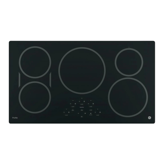
36" ELECTRONIC INDUCTION COOKTOP
WARNING
Electrical Shock Hazard
Death or serious injury can result from failure to follow these
instructions.
• Service by a qualified service technician only.
• Disconnect power before servicing this product.
• Reconnect all grounding devices after service.
• Replace all parts and panels before operating.
GROUNDING SPECIFICATIONS
Ground Path Resistance
0.10
Max.
Insulation Resistance
250 K Min.
INSTALLATION REQUIREMENTS
Power Supply
The cooktop must be connected to a supply circuit of the proper
voltage and frequency as specified on the rating plate. Wire size
must conform to the National Electrical Code or the prevailing local
code. The rating plate is located on the bottom of the burner box.
OVERCURRENT PROTECTION
36 Cooktops
NEC RATING
MAXIMUM KILOWATT RATING
208V
240V
50 Amp
10.4
12.0
The branch circuit load for one counter-mounted cooktop is the
rating on the nameplate of the appliance.
WIRING
Built-in power leads are UL-approved for connection to larger
gauge household wiring. The insulation of these leads is rated
at temperatures much higher than the temperature rating of
household wiring. The current-carrying capacity of a conductor is
governed by the temperature rating of the insulation around the
wire rather than the wire gauge alone.
WARNING:
IMPROPER CONNECTION OF ALUMINUM
HOUSE WIRING TO THESE COPPER LEADS CAN RESULT IN
A SERIOUS PROBLEM. USE ONLY CONNECTORS DESIGNED
FOR JOINING COPPER TO ALUMINUM AND FOLLOW THE
MANUFACTURER'S RECOMMENDED PROCEDURE CLOSELY.
CERAMIC GLASS COOKTOP
If the glass is damaged it must be replaced in combination with
the touch board; these two components come from the factory as
a single assembly. Do NOT attempt to remove and reuse the touch
board.
IMPORTANT
SERVICE INFORMATION
DO NOT DISCARD
31-17142 10-14 GE
Model Number - PHP9036
APPEARANCE DEFECTS
Scratches, marks, discoloration, stains, spots, etc. can be caused
by food, cookware, utensils, cleaning solutions or water.
BEFORE replacing the COOKTOP, use the cooktop cleaning
procedure outlined in the Owner's Manual.
NOTE: When servicing the cooktop, care must be taken not to
scratch or damage the glass.
• All components are accessible by removing the glass top.
DISASSEMBLY OF THE COOKTOP
follow these steps:
• Remove external screws from all 4 sides of the burner box.
terminals from the induction tray and RJ-45. Remove Glass and
Module assembly and place on a towel or padded surface.
• Remove external screws from all 4 brackets to the aluminum
plate.
• Remove the screws holding the aluminum plate to the generator
modules. Loosen the screws holding the terminated element
wires to the generator board. The logic harness runs between the
two trays.
• When replacing the module or fan, make sure the respective
gasket is in place.
REASSEMBLY OF THE COOKTOP
To reassemble, follow these steps:
• Place the shield over the modules and reverse the steps above.
See schematic for where elements are wired.
• It is easiest to drive one corner screw and then shift the
generator module as necessary to align other holes.
Reverse disassembly process. The wires are color coded with text
on the underside of the induction tray.
The two hex head screws by the louvers are to ensure that the
exhaust air from the louvers are not blocked by the counter or
cabinets.
Element Induction - 5X
Cover Heat Sink
Left
Blower Centrifugal 12V
Left
Gasket Fan
Left
Board Generator ASM - 2X
Left
Board Filter
Left
Induction Tray
Left
Gasket Bottom
Left
Enclosure Fan
Left
Cover Hole
Housing RJ45
Board RJ45 Connector
Bracket Hold Down - 2X
Maintop Glass ASM
Plate Aluminum
Insulation Induction
Cover Heat Sink
Right
Blower Centrifugal 12V
Right
Gasket Fan
Right
Shield EMI
Left
Board Generator ASM
Right
Shield EMI
Right
Board Filter
Right
Induction Tray
Right
Gasket Bottom
Right
Enclosure Fan
Right
Bottom Burn Box
Conduit Wire ASM
Baffle

Related Manuals for GE Profile PHP9036


Summary of Contents for GE Profile PHP9036
- Page 1 Do NOT attempt to remove and reuse the touch Housing RJ45 Bottom Burn Box board. Board RJ45 Connector IMPORTANT Conduit Wire ASM SERVICE INFORMATION Bracket Hold Down - 2X DO NOT DISCARD Baffle 31-17142 10-14 GE Model Number - PHP9036...
- Page 2 Fan, UI and induction Tray. J8 Pin7 Fan Low Speed. +5VDC Active service replacement board. RJ-45 is a service jack provided for GE technicians to use on the Replace fan. J8 Pin8 front left bottom corner of the unit. Fan2 is not running at...
- Page 3 C THERMISTOR 229C6361G003 229C6361G001 (2.00) 1BK BOARD ID GEN BOARD CTR (2.00) 1BK J502 BOARD ID BOARD ID GEN BOARD LT J502 BOARD ID IMPORTANT SERVICE INFORMATION USER INTERFACE BOARD DO NOT DISCARD 31-17142 10-14 GE Model Number - PHP9036...
- Page 4 RACCORDER DU CUIVRE SUR DE L’ALUMINIUM ET RESPECTEZ châssis - Droite SCRUPULEUSEMENT LA PROCÉDURE RECOMMANDÉE PAR LE Boîtier RJ-45 FABRICANT. Caisson de brûleur inférieur Connecteur RJ-45 INFORMATION DE SERVICE IMPORTANTE Ferrure de retenue - 2x NE PAS JETER Déflecteur 31-17142 10-14 GE Numéros De Modèle - PHP9036...
- Page 5 Remplacer la carte IU. J1 Pin6 sonnerie et voir la version du logiciel sur la minuterie. secondes. (Sur les IU des appareils GE, toutes les DEL peuvent Impossible de s’allumer durant les premières 10 secondes avant de voir SEt J1 Pin7 Le tableau ci-dessous décrit les diagnostics associés à...
- Page 6 229C6361G003 229C6361G001 (2.00) 1BK BOARD ID GEN BOARD CTR (2.00) 1BK J502 BOARD ID BOARD ID GEN BOARD LT J502 BOARD ID INFORMATION DE SERVICE IMPORTANTE USER INTERFACE BOARD NE PAS JETER 31-17142 10-14 GE Numéros De Modèle - PHP9036...