Available languages
Available languages
Quick Links
Before you begin - Read these instructions completely
and carefully. IMPORTANT – OBSERVE ALL
GOVERNING CODES AND ORDINANCES. Note to
Installer – Be sure to leave these instructions with the
Consumer. Note to Consumer – Keep these instructions
with your Owner's Manual for future reference.
NOTES:
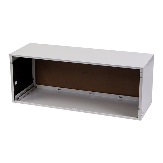
• Handle the case carefully.
• The cardboard stiffener inside the case, and the rear
protective panel must retain in place until the chassis
is installed to assure case rigidity and squareness.
• If a sub-base is to be used, it may be desirable to
assemble it to the case before securing the case in
the wall.
CRITICAL DIMENSIONS
Outside wall
"C"
NOTE: Care should be taken in location of electrical
supply entry in relationship to wall sleeve to ensure
access to power once the unit is installed.
Ceiling
"A"
"B"
Roomside
"D"
Installation Instructions
for your new
RAB81
Assembly Required
RAB81B
Fully Assembled
Wall Case for All AZ Series
Zoneline Models
CASE LOCATION
Dimensions Recommended Installation Clearance
A
B
recommended.
C
D
E
INSTALL CASE LEVEL IN ALL DIRECTIONS
Top of case
"E"
31-5000402 Rev. 0 03-19 GEA
Outside wall
"E"

Related Manuals for GE RAB81


Summary of Contents for GE RAB81
- Page 1 Installation Instructions for your new RAB81 Assembly Required RAB81B Before you begin - Read these instructions completely Fully Assembled and carefully. IMPORTANT – OBSERVE ALL GOVERNING CODES AND ORDINANCES. Note to Installer – Be sure to leave these instructions with the Wall Case for All AZ Series Consumer.
-
Page 2: Installation Instructions
Installation Instructions STEP 1: Preparation of the wall STEP 2: Preparation of the RAB81 only case Assemble Wall Sleeve Front View 2. Locate left side panel. Front View Front View Header - 4” x 4” or Main stud two 2” x 4” on edge Jack studs 4. - Page 3 Installation Instructions STEP 4: RAB81, RAB81B Installation of the case in the wall opening Steel lintel Caulk* Caulk* Room IMPORTANT: Case cabinet Install case level from side to side and from front to rear. Outdoor Using a level, allowable tilt to the outside is maximum of grille 1/4 bubble.
-
Page 4: Drain Kit
Installation Instructions Electrical Requirements (230V/208V) Drain Kit RAD10 Internal/External Drain Wall Case with RAD10 Drain Unit Internal Drain NOTE: Shaded parts Note: S haded part s included with RAD10 included w ith See detail “G” drain Kit. “F” RAD10 dr ain ki t below Inside Square drain holes... - Page 5 Instructions d’installation pour le nouveau RAB81 Assemblage requis RAB81B Complètement assemblé Avant de commencer - Veuillez lire ces instructions attentivement et en totalité. IMPORTANT – OBSERVEZ TOUS LES CODES ET RÈGLEMENTS EN VIGUEUR. Gaine murale pour tous les modèles Note à l’installateur – Assurez-vous de laisser ces instructions au consommateur.
-
Page 6: Instructions D'installation
Cripple Rear View Jack studs REMARQUE : ÉTAPE 3 : (facultatif) RAB81, RAB81B Utilisez un linteau pour supporter les briques, les Cornières de gaine blocs, etc., au-dessus de la gaine du climatiseur. (Il n’est pas nécessaire d’utiliser un linteau immédiate- ment sous un seuil de fenêtre.) - Page 7 Instructions d’installation ÉTAPE 4: RAB81, RAB81B Installation de ÉTAPE 5: Étanchéisation la gaine dans l’ouverture murale et la gaine avec du calfeutrage ou un produit d’étanchéisation équivalent. et prévenir le scellement des trous de vidange dans le re- bord arrière de la gaine. Cela facilite l’installation d’un drain...
- Page 8 Square drain holes Neoprene sponge gasket ” O.D. drain tube Steel mounting plate directement dans une prise murale exposée. Type “A” screws raccorder l’alimentation électrique. REMARQUE: Il peut être souhaitable ou nécessaire celle-ci dans le mur. Un produit de qualité GE Appliances...