
Related Manuals for Honeywell MO953 Series


Summary of Contents for Honeywell MO953 Series
-
Page 3: Specifications
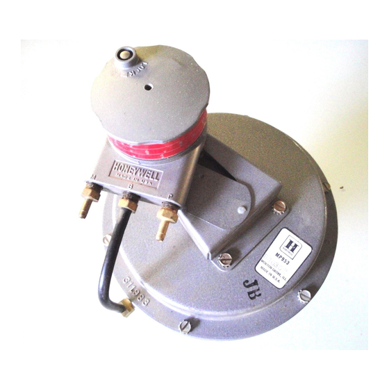
GENERAL DESCRIPTION proportionally control steam or hot and cold liquids in The MO953 and MP953 Pneumatic Valve Actuators HVAC systems. (“Actuators”) are used with V5011 and V5013 Valves and can control older steam and water valves via adapters. The SPECIFICATIONS directed to the MP953 Actuators. - Page 4 Table 1. MO953hW53 Specifications (Continued). MP953 MO953 Travel in Device Type Active Inactive Active Inactive In (mm) In (mm) Cl166 Direct acting no Relay or positioner 8-12 (55-83) 4-l 1 (28-76) 250 (121) 3-7 (21-48) 8-12 (55-83) 4-l 1(28-76) 8 (203) 160 (71) 3-7 (21-48) 8-12 (55-83)
-
Page 5: Operation
OPERATION THERMOSTAT In a direct-acting (n.o. valve) system, an increase in POSITIONER control (branch/pilot) air pressure forces the Actuator diaphragm and cup assembly downward, forcing the valve stem down to proportionally close off the flow through the valve (Fig. 1). In a reverse-acting (nc. - Page 6 SET OPERATING RANGE Change the operating range of MP953E and F by replacing the feedback spring with one for the range (see REPAIR). Use Wrench 301572A to loosen the cover locking screw (Fig. 2). Unscrew the start point adjustment knob until thread ADJUST START POINT is disengaged.
-
Page 7: Troubleshooting
TROUBLESHOOTING EQUIPMENT NEEDED SYMPTOMS AND CORRECTIVE ACTION Troubleshooting procedures require Pressure Gage 14003519 (0 to 30 psi [O to 207 kPa]). Figures 3 and 4 show troubleshooting flowcharts. CHECK THAT ACTUATOR IS SECURELY MOUNTED AND STEM EU-lTON IS PROPERLY LATCHED PRESSURETO DOES RANGE VALUE... - Page 8 IS SECURELY h4OUNTED AND STEM 6UlTON Is PROPERLY LATCHED REPLACE ACTUATOR ADEQUATE FOR DIAPHRAGM AND/OR COMPLETE SLEEVE ACTUATOR IS OK. RESTORE SYSTEM TO SERVICE. MATERIAL; AND/OR REPAIR DISC, SEAT, AND STEM; AND/OR REPACK VALVE Fig. 4. Troubleshooting Flowchart for MP953C, D (without Gradutrol Relay/Positioner).
- Page 9 REPAIR Table 4. Loosening and Removing Actuator Bases from Valve Bonnets. GENERAL Device Actuator Tools Required Series Dia (In.) Model This section lists tools needed to disassemble and reassemble Actuators and gives procedures for replacing or T-25 Torx bit parts of actuators. See PARTS AND ACCESSORIES for parts diagrams and lists.
- Page 10 GRA DUTRO 31371 I SPRING -@ 313695 J 6-32 X l/4 ROUND H SCREW 0-80X 5/16 ROUND HD NUT OS0 X .05 IN. THICK PARTS BELOW COMMON TO AU RELAYS PARTS BELOW COMMON TO ALL RELAYS VALVE UNIT CUP ASSY THE 313711A AND D MODELS HAVE DUAL BARBED CONNECTORS;...
- Page 11 CONVERSION MO953 Maximum temperature 250F (121C) CONVFRT A8 DWICF- JO CONVFRT A4 DFVICF- Used on MP953B, D and F - S C R E W 13 IN. (330 MM) RELAY ASSY 313695J RELAY ASSY 313695J FEEDBACK SPRING FEEDBACK SPRING Maximum temperature 250F (12 1C) 3 13696-00063 CUP 315178-00062 CUP 315178-00062...
- Page 12 Reinstall small sleeve cup, ring, and screws. replace every second cover screw with a 5/ Install new main diaphragm, checking that it is 16-18 x 3 in. bolt. properly located. 7. Continue sequentially loosening all bolts/screws until Reinstall cup, lockwasher, and nut. Tighten nut all original (short) bolts/screws are disengaged.
- Page 13 NOTE: Considerable force may be required before See WARNING in this section. Sequentially loosen fasteners securing base to frame. Base pops up from the positioner begins to turn because of the frame when fasteners disengage. large O-ring that seals the Relay/positioner to the Actuator cover.
- Page 14 Check that ends of bias and feedback springs are Replace service plate and reinstall positioner. properly located. Install new Relay/positioner 6. Reconnect tubing and restore system to service. bracket assembly on Actuator cover. Replace short tube from Relay/positioner branch port INSTALL STEM ANTISPIN to fitting on side of Actuator cover.
-
Page 15: Parts And Accessories
PARTS Figures 8 through 11 show exploded diagrams of 11 list parts shown in the figures. Fig. 9. MO/MP953B and MP953F Exploded View. Fig. 8. MO/MP953A and MP953E Exploded View. - Page 16 Table 6. MOLMP953A and MP953E Parts. Feedback spring for l-l/2-in. stroke MP953A (see NOTE 2) 313696-00063 Feedback spring for 3/4-in. stroke MP953A (see NOTE 2) Frame for g-in. models, includes screws Frame for 13-in. models Base for 5-in. models, includes screws Base for g-in.
- Page 17 Table 7. MO/MP953B and MP953F Parts. Description Part Number Gradutrol Relay assembly for MP953B, use 14004138-001 Positive Positioning Retrofit Kit. Obtain locally Hex-head screw (2), lo-24 x 506 in. 3 16579 Filters (3) Tubing connector, l/8 NPT, for MP953B Obtain locally Positive positioner and bracket assembly for MP953F, includes filter 14001865-001 Copper or plastic tubing, l/4 in.
- Page 18 Fig. 10. MOjMP953C Exploded View. Fig. 11. MO/MP9531> Exploded View_...
- Page 19 Table 8. MO/MP953C Parts. Description Part Number 312817 Cover for 5-in. Series 2 model Cover for 8-in. model 311748 Cover for 13-m. model 312103 Obtain locally Fillister-head screw, 6-32 x l/2 in. for early models (8) Fillister-head screw, 8-32 x l/2 in. for 5-in. model (4) Obtain locally Obtain locally Filhster-head screw, l/4-20 x 3/4 in.
- Page 20 Table 9. MO/MP953D Parts. Obtain locally Hex-head screw with lockwasher (6), lo-24 x 3/4 in. 1 4 0 0 4 6 6 0 - 0 0 1 Cover 3 1220.5 304733-00021 Lockwasher 312199 Washer for 3/4-in. stroke model 12200-00767 3 14650A Support Assembly with helicoil insert for Series 2 models only.
- Page 21 POSITIONER RETROFIT AND SPRING KITS Table 12. MP953 Positive Positioner Retrofit Kits. Table 13. MP953 Feedback Spring Kits. Part No. Part No. Description* Description* 1400421 l-001 For 3/4-in. (19-mm) stroke DA vahs 14004138-001 For RA valve actuators (Fig 12) 14004139-001 For 8- and 13-in. (203- and 330-mm), 14004213-001 For RA valve actuators (includes bias actuators (Fig.
- Page 22 GREEN BLUE 10 PSI (69 KPA) GRAY 5 PSI (34 KPA) YELLOW 5 PSI (34 KPA) O-RING 312602 3 PSI (21 KPA) B L A C K D-RING 312602 FEEDBACK SPRING KIT FEEDBACK SPRING K Fig. 14. Positive Positioner Retrofit Kit 14QO4 140-001 Fig.
- Page 23 EXTENSION 312518-00062 BUTTON ACTUATOR STEM EXTENSION 311851-00062 - 8 IN. MODEL ACTUATOR STEM AND SETSCREW 13 IN. MODEL. l-1/2 IN. STROKE 314 IN. STROKE ADAPTER POSITION INDICATOR FOR. ADAPTS MP953C TO V053, REFERENCE iNFORMATION ON VALVES, SEE 95-5579 Fig. 15. MSC 3858...
- Page 24 Honeywell Home and Building Control Home and Building Control Helping You Control Your World Honeywell Inc. Honeywell Limited-Honeywell Limit&z Honeywell Plaza 740 Ellesmere Road P.O. Box 524 Scarborough, Ontario Minneapolis, MN 55408-0524...