Mitsubishi Electric FR-D700 Series Instruction Manual
Hide thumbs
Also See for FR-D700 Series:
- Instruction manual (290 pages) ,
- Manual (34 pages) ,
- Installation manuallines (28 pages)
INVERTER
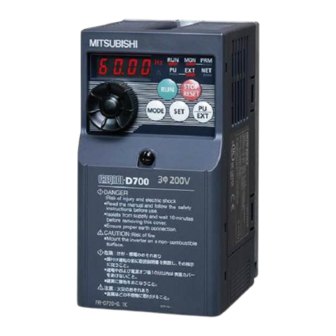
FR-D700
INSTRUCTION MANUAL (BASIC)
FR-D720-0.1K to 15K
FR-D740-0.4K to 15K
FR-D720S-0.1K to 2.2K
FR-D710W-0.1K to 0.75K
Thank you for choosing this Mitsubishi Electric Inverter.
This Instruction Manual (Basic) provides handling information and precautions for use of the equipment.
Please forward this Instruction Manual (Basic) to the end user.
OUTLINE ...................................................................................1
1
INSTALLATION AND WIRING ...................................................5
2
PRECAUTIONS FOR USE OF THE INVERTER.........................19
3
4
DRIVING THE MOTOR.............................................................23
5
ENERGY SAVING OPERATION FOR FANS AND PUMPS ........31
6
PARAMETERS .........................................................................32
7
TROUBLESHOOTING ..............................................................36
8
PRECAUTIONS FOR MAINTENANCE AND INSPECTION ........41
9
SPECIFICATIONS ....................................................................43
10
To obtain the Instruction Manual (Applied) and the
Safety stop function instruction manual
Contact where you purchased the inverter, your Mitsubishi Electric sales
representative, or the nearest Mitsubishi Electric FA Center for the
following manuals:
Instruction Manual (Applied) [IB(NA)-0600366ENG]
Safety stop function instruction manual [BCN-A211508-000]
These manuals are required if you are going to utilize functions and
performance.
The PDF manuals are also available for download at the Mitsubishi
Electric FA Global Website (URL: http://www.MitsubishiElectric.co.jp/fa/).
CONTENTS
700
1
2
3
4
5
6
7
8
9
10
Table of Contents

Related Manuals for Mitsubishi Electric FR-D700 Series


Summary of Contents for Mitsubishi Electric FR-D700 Series
-
Page 1: Table Of Contents
SPECIFICATIONS ..............43 To obtain the Instruction Manual (Applied) and the Safety stop function instruction manual Contact where you purchased the inverter, your Mitsubishi Electric sales representative, or the nearest Mitsubishi Electric FA Center for the following manuals: Instruction Manual (Applied) [IB(NA)-0600366ENG] ... - Page 2 This Instruction Manual (Basic) provides handling information and precautions for use of this product. Please forward this Instruction Manual (Basic) to the end user. 2. Fire Prevention This section is specifically about safety matters CAUTION Do not attempt to install, operate, maintain or inspect this ...
- Page 3 The inverter must be used for three-phase induction motors. Caution labels are used to ensure safety during use of Connection of any other electrical equipment to the product Mitsubishi Electric inverters. output may damage the equipment. Apply the following labels to the inverter if the "retry function"...
-
Page 4
PU: Operation panel and parameter unit (FR-PU04/FR-PU07) Inverter: Mitsubishi Electric inverter FR-D700 series FR-D700: Mitsubishi Electric inverter FR-D700 series Pr.: Parameter number (Number assigned to function) PU operation: Operation using the PU (operation panel/FR-PU04/FR-PU07) ... -
Page 5: Outline
1 OUTLINE Product checking and parts identification Unpack the inverter and check the capacity plate on the front cover and the rating plate on the inverter side face to ensure that the product agrees with your order and the inverter is intact. Inverter model FR - D740... - Page 6 Lit to indicate monitoring mode. etc. STOP operation Setting dial Used to stop operation commands. (Setting dial: Mitsubishi Electric inverter Used to reset a fault when the protective dial) function (fault) is activated. The setting dial is used to change the frequency and parameter settings.
- Page 7 Operation panel 1.2.2 Basic operation (factory setting) Operation mode switchover At power-ON (External operation mode) PU Jog operation mode (Example) PU operation mode Value change and frequency appear alternately. (output frequency monitor) Frequency setting has been written and completed. STOP Output current monitor Output voltage monitor Display the...
- Page 8 Operation panel 1.2.3 Changing the parameter setting value Operation example Change the Pr. 1 Maximum frequency setting. Operation Screen at power-ON The monitor display appears. REMARKS Operation mode change is displayed...Why? Press to choose the PU operation mode. PU indicator is lit. Parameter setting mode appears ..Write disable error appears ..
-
Page 9: Installation And Wiring
2 INSTALLATION AND WIRING AC power supply Use within the permissible power supply specifications of the inverter. To ensure safety, use a molded case circuit breaker, RS-232C - RS-485 converter is earth leakage circuit breaker or magnetic Enclosure surface operation required when connecting to PC contactor to switch power ON/OFF. - Page 10 Peripheral devices Peripheral devices Check the inverter model of the inverter you purchased. Appropriate peripheral devices must be selected according to the capacity. Refer to the following list and prepare appropriate peripheral devices. Molded Case Circuit Breaker (MCCB) Input Side Magnetic or Earth Leakage Circuit Reactor Motor...
- Page 11 Installation of the inverters and precautions Installation of the inverters and precautions (1) Installation of the inverter Enclosure surface mounting Remove the front cover and wiring cover to mount the inverter to the surface. (Remove the covers in the directions of the arrows.) FR-D720-0.1K to 0.75K FR-D720-1.5K to 3.7K...
- Page 12 Wiring Wiring 2.3.1 Terminal connection diagram 1 DC reactor (FR-HEL) *6 Terminal P1 is not available for When connecting a DC reactor, remove the single-phase 100V power input model. Sink logic jumper across P1 and P/+. Main circuit terminal Single-phase 100V power input model is *7 Brake resistor (FR-ABR, MRS type, MYS type) not compatible with DC reactor.
- Page 13 Wiring 2.3.2 Terminal specifications Terminal Type Terminal Name Terminal Specification Symbol Connect to the commercial power supply. R/L1, S/L2, Do not connect anything to these terminals when using the high power factor converter (FR- AC power input T/L3 HC2) or power regeneration common converter (FR-CV). ...
- Page 14 Wiring Terminal Type Terminal Name Terminal Specification Symbol 1 changeover contact output indicates that the inverter Contact capacity:230VAC Relay output protective function has activated and the output stopped. A, B, C 0.3A (power factor =0.4) (fault output) Fault: discontinuity across B-C (continuity across A-C), 30VDC 0.3A Normal: continuity across B-C (discontinuity across A-C) Switched Low when the inverter output frequency is equal to or...
- Page 15 Wiring 2.3.3 Terminal arrangement of the main circuit terminal, power supply and the motor wiring Three-phase 200V/400V class FR-D720-0.1K to 0.75K FR-D720-1.5K to 3.7K FR-D740-0.4K to 3.7K Jumper N/- P/+ Jumper R/L1 S/L2 T/L3 R/L1 S/L2 T/L3 Power supply Motor Motor Power supply...
- Page 16 Wiring (1) Cable sizes etc., of the main control circuit terminals and earth (ground) terminals Select the recommended cable size to ensure that a voltage drop will be 2% or less. If the wiring distance is long between the inverter and motor, a main circuit cable voltage drop will cause the motor torque to decrease especially at the output of a low frequency.
- Page 17 Wiring (2) Total wiring length The overall wiring length for connection of a single motor or multiple motors should be within the value in the table below. Cable Pr. 72 Setting 3.7K Voltage Class 0.1K 0.2K 0.4K 0.75K 1.5K 2.2K Type (carrier frequency) or Higher...
- Page 18 Wiring (2) Wiring method Wiring Use a blade terminal and a wire with a sheath stripped off for the control circuit wiring. For a single wire, strip off the sheath of the wire and apply directly. Insert the blade terminal or the single wire into a socket of the terminal. 1) Strip off the sheath about the length below.
- Page 19 Wiring Wire removal Pull the wire with pushing the open/close button all the NOTE way down firmly with a flathead screwdriver. Pulling out the terminal block forcefully without pushing Open/close button the open/close button all the way down may damage the terminal block.
- Page 20 Wiring 2.3.5 Assigning signals (output stop signal (MRS), reset signal (RES), etc.) to contact input terminals POINT Use Pr.178 to Pr.182 (input terminal function selection) to select and change the functions assigned to input terminals. To assign the output stop signal (MRS) to the terminal RH, for example, assign "24" to Pr.182 RH terminal function selection.
- Page 21 Wiring 2.3.6 Safety stop function (1) Description of the function The terminals related to the safety stop function are shown below. Terminal Description Symbol For input of safety stop channel 1. Between S1 and SC / S2 and SC Open: In safety stop mode.
- Page 22 (Always install a thermal relay when using a brake resistor whose capacity is 11K or higher.) When the power supply is 400V class, install a step-down transformer. Power Thermal Relay Type Supply Brake Resistor (Mitsubishi Electric Rated Operating Current Voltage product) MRS120W200 TH-T25-0.7A 120VAC: 2A (NO contact) /...
-
Page 23: Precautions For Use Of The Inverter
PRECAUTIONS FOR USE OF THE INVERTER 3 PRECAUTIONS FOR USE OF THE INVERTER The FR-D700 series is a highly reliable product, but using incorrect peripheral circuits or incorrect operation/handling methods may shorten the product life or damage the product. Before starting operation, always recheck the following items. - Page 24 PRECAUTIONS FOR USE OF THE INVERTER (10) A short circuit or earth (ground) fault on the inverter output side may damage the inverter modules. Fully check the insulation resistance of the circuit prior to inverter operation since repeated short circuits may damage ...
- Page 25 PRECAUTIONS FOR USE OF THE INVERTER (19) Instructions for overload operation When performing operation of frequent start/stop of the inverter, rise/fall in the temperature of the transistor element of the inverter will repeat due to a repeated flow of large current, shortening the life from thermal fatigue. Since thermal fatigue is related to the amount of current, the life can be increased by reducing current at locked condition, starting current, etc.
-
Page 26: Failsafe Of The System Which Uses The Inverter
When a fault occurs, the inverter output is shut off to output a fault signal. However, a fault output signal may not be output at an inverter fault occurrence when the detection circuit or output circuit fails, etc. Although Mitsubishi Electric assures best... -
Page 27: Driving The Motor
Start/stop from the operation panel (PU operation) 5 DRIVING THE MOTOR The inverter needs frequency command and start command. Frequency command Frequency command (set frequency) determines the rotation speed of the motor. Turning ON the start command starts the motor to rotate. Frequency Output (Hz) - Page 28 Start/stop from the operation panel (PU operation) 5.1.2 Using the setting dial like a potentiometer to perform operation POINT Set "0" (extended parameter valid) in Pr. 160 Extended function display selection. Set "1" (setting dial potentiometer mode) in Pr. 161 Frequency setting/key lock operation selection. Operation example Change the frequency from 0Hz to 60Hz during operation Operation...
- Page 29 Start/stop from the operation panel (PU operation) 5.1.3 Setting the frequency by switches (three-speed setting) (Pr. 4 to Pr. 6) POINT Use the operation panel ( to give a start command. Switch ON the RH, RM, or RL signal to give a frequency command. ...
- Page 30 Start/stop from the operation panel (PU operation) 5.1.4 Setting the frequency by analog input (voltage input/current input) POINT Use the operation panel ( ) to give a start command. Use the potentiometer (frequency setting potentiometer) (voltage input) or 4-to-20mA input (current input) to give a frequency command.
- Page 31 Start and stop using terminals (External operation) Start and stop using terminals (External operation) POINT From where is the frequency command given? Operation at the frequency set in the frequency setting mode of the operation panel Refer to 5.2.1 (Refer to page 27) ...
- Page 32 Start and stop using terminals (External operation) 5.2.2 Setting the frequency by switches (three-speed setting) (Pr. 4 to Pr. 6) POINT Switch ON the STF (STR) signal to give a start command. Switch ON the RH, RM, or RL signal to give a frequency command. [Connection diagram] Inverter Speed 1...
- Page 33 Start and stop using terminals (External operation) 5.2.3 Setting the frequency by analog input (voltage input/current input) POINT Switch ON the STF (STR) signal to give a start command. Use the potentiometer (frequency setting potentiometer) (voltage input) or 4-to-20mA input (current input) to give a frequency command.
- Page 34 Start and stop using terminals (External operation) 5.2.4 Operating at 60Hz or higher using the external potentiometer < How to change the maximum frequency> Changing When you want to use 0 to 5VDC input frequency setting potentiometer to change the frequency at 5V from 60Hz (initial value) example to 70Hz, make adjustment to output "70Hz"...
-
Page 35: Energy Saving Operation For Fans And Pumps
ENERGY SAVING OPERATION FOR FANS AND PUMPS 6 ENERGY SAVING OPERATION FOR FANS AND PUMPS Set the following functions to perform energy saving operation for fans and pumps. (1) Load pattern selection (Pr. 14) Select the optimum output characteristic (V/F characteristic) that is suitable for the Pr. -
Page 36: Parameters
Simple mode parameters 7 PARAMETERS Simple variable-speed operation can be performed with the inverter in the initial settings. Set the required parameters according to the load and operating conditions. Use the operation panel to set or change a parameter. (Refer to Chapter 4 of the Instruction Manual (Applied) for the detailed description of parameters.) Simple mode parameters... - Page 37 Parameter list Parameter list REMARKS indicates simple mode parameters. The parameters surrounded by a black border in the table allow its setting to be changed during operation even if "0" (initial value) is set in Pr. 77 Parameter write selection. Initial Initial Name...
- Page 38 Parameter list Initial Initial Name Setting Range Name Setting Range Value Value Rated motor frequency 10 to 120Hz 60Hz STF terminal function selection Motor constant (R1) 0 to 50 , 9999 9999 STR terminal function Auto tuning setting/status 0, 11, 21 0 to 5, 7, 8, 10, selection PU communication station...
- Page 39 Parameter list Initial Initial Name Setting Range Name Setting Range Value Value Parameter for manufacturer setting. Do not set. FM terminal calibration — — (900) Magnitude of frequency 0, 0.01, 0.10, change setting 1.00, 10.00 Terminal 2 frequency setting 1 to 6, 0 to 400Hz Password lock level...
-
Page 40: Troubleshooting
Reset method of protective function 8 TROUBLESHOOTING When a fault occurs in the inverter, the inverter output is shut off and the PU display automatically changes to one of the following fault or alarm indications. If the fault does not correspond to any of the following faults or if you have any other problem, please contact your sales representative. - Page 41 List of fault displays List of fault displays When a fault occurs in the inverter, the inverter trips and the PU display automatically changes to one of the following fault or alarm indications. The error message shows an operational error. The inverter output is not shut off. Warnings are messages given before faults occur.
- Page 42 List of fault displays Function Name Description Corrective action Display Set the acceleration time longer. (Shorten the downward acceleration time in vertical lift application.) If "E.OC1" always appears at start, disconnect the motor once and restart the inverter. If "E.OC1" still appears, the inverter may be faulty.
- Page 43 List of fault displays Function Name Description Corrective action Display Reduce the load and operate less frequently. The external thermal relay connected to the OH External thermal relay Even if the relay contacts are reset automatically, the inverter operation...
- Page 44 Check first when you have a trouble Check first when you have a trouble Description Countermeasure Check start and frequency command sources and enter a start command (STF, etc.) and a Motor does not start. frequency command. Motor or machine is making abnormal Take EMC measures if a steady operation cannot be performed due to EMI.
-
Page 45: Precautions For Maintenance And Inspection
Inspection items 9 PRECAUTIONS FOR MAINTENANCE AND INSPECTION The inverter is a static unit mainly consisting of semiconductor devices. Daily inspection must be performed to prevent any fault from occurring due to the adverse effects of the operating environment, such as temperature, humidity, dust, dirt and vibration, changes in the parts with time, service life, and other factors. - Page 46 Estimated lifespan for when the yearly average surrounding air temperature is 40°C (without corrosive gas, flammable gas, oil mist, dust and dirt etc.) Output current: 80% of the inverter rated current NOTE For parts replacement, contact the nearest Mitsubishi Electric FA Center.
-
Page 47: Specifications
Rating 10 SPECIFICATIONS 10.1 Rating Three-phase 200V power supply Model FR-D720-K 0.75 Applicable motor capacity (kW) 0.75 Rated capacity (kVA) 12.7 17.9 23.1 Rated current (A) 10.0 16.5 23.8 31.8 45.0 58.0 Overload current rating 150% 60s, 200% 0.5s (inverse-time characteristics) ... - Page 48 Approximate mass (kg) The applicable motor capacity indicated is the maximum capacity applicable for use of the Mitsubishi Electric 4-pole standard motor. The rated output capacity assumes the following output voltages: 230V for three-phase 200V/single-phase 200V/single-phase 100V, and 440V for three- phase 400V.
- Page 49 Outline dimension drawings 10.3 Outline dimension drawings FR-D720-0.1K to 0.75K FR-D720-1.5K to 15K FR-D720S-0.1K to 0.75K FR-D740-0.4K to 15K FR-D710W-0.1K to 0.4K FR-D720S-1.5K, 2.2K FR-D710W-0.75K φC φC (Unit: mm) Three-phase 200V class Inverter Model FR-D720-0.1K 80.5 FR-D720-0.2K FR-D720-0.4K 112.5 FR-D720-0.75K 132.5 FR-D720-1.5K...
- Page 50 CE marking. The authorized representative in the EU The authorized representative in the EU is shown below. Name: Mitsubishi Electric Europe B.V. Address: Mitsubishi-Electric-Platz 1, 40882 Ratingen, Germany (1) EMC Directive We declare that this inverter, when equipped with the EMC Directive compliant EMC filter, conforms with the EMC Directive and affix the CE marking on the inverter.
- Page 51 (2) Low Voltage Directive We have self-confirmed our inverters as products compliant to the Low Voltage Directive and affix the CE marking on the inverters. Low Voltage Directive: 2014/35/EU Standard: EN61800-5-1:2007 Outline of instructions Do not use an earth leakage circuit breaker as an electric shock protector without connecting the equipment to the earth. Connect the equipment to the earth securely.
- Page 52 When you set the electronic thermal relay function dedicated to the Mitsubishi Electric constant-torque motor, this characteristic curve 105% 52.5% applies to operation at 6Hz or higher. (For selection of the operation characteristic, Inverter output current (%) (% to the inverter rated current) refer to Chapter 4 of the Instruction Manual.)
- Page 53 Model Manufacturer Rated Voltage, Vac MMP-T32 Mitsubishi Electric Corp. 480Y/277 Suitable for use in a circuit capable of delivering not more than 50 or 25 kA rms symmetrical amperes, 480Y/277 volts maximum when protected by the Type E combination motor controllers indicated in the above table.
- Page 54 The SERIAL number (refer to Appendix 3) can be checked on the rating plate (refer to page 1) of the product. • Authorized sales representative (importer) in the CU area The authorized sales representative (importer) in the CU area is shown below. Name: Mitsubishi Electric (Russia) LLC Address: 52, bld 1 Kosmodamianskaya Nab 115054, Moscow, Russia Phone: +7 (495) 721-2070...
- Page 55 Appendix 5 Restricted Use of Hazardous Substances in Electronic and Electrical Products The mark of restricted use of hazardous substances in electronic and electrical products is applied to the product as follows based on the “Management Methods for the Restriction of the Use of Hazardous Substances in Electrical and Electronic Products”...
- Page 56 (1) Damages caused by any cause found not to be the responsibility of Mitsubishi Electric. (2) Loss in opportunity, lost profits incurred to the user by Failures of Mitsubishi Electric products. (3) Special damages and secondary damages whether foreseeable or not, compensation for accidents, and compensation for damages to products other than Mitsubishi Electric products.
- Page 57 MEMO...
- Page 58 REVISIONS *The manual number is given on the bottom left of the back cover. Revision Date Revision Manual Number Aug. 2010 IB(NA)-0600438ENG-A First edition Apr. 2012 IB(NA)-0600438ENG-B Addition Safety stop function Energy saving operation for fans and pumps Jun.
- Page 59 COMERCIO E SERVICOS LTDA. (CHINA) LTD. Tianjin FA Center India Pune FA Center Avenida Adelino Cardana, 293, 21 andar, Room 2003 City Tower, No.35, Youyi Road, MITSUBISHI ELECTRIC INDIA PVT. LTD. Bethaville, Barueri SP, Brazil Hexi District, Tianjin, China Pune Branch TEL. 55-11-4689-3000 TEL.
- Page 60 HEAD OFFICE: TOKYO BUILDING 2-7-3, MARUNOUCHI, CHIYODA-KU, TOKYO 100-8310, JAPAN FR-D700 MODEL INSTRUCTION MANUAL (BASIC) MODEL 1A2-P34 CODE IB(NA)-0600438ENG-D(1901)MEE Printed in Japan Specifications subject to change without notice.