Table of Contents
Quick Links
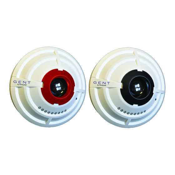
S4 Beam Sensor & brackets
(for Vigilon and Nano Systems)
Transmitter (red retainer) Receiver (black retainer)
¨
Beam sensor pair (Transmitter & Receiver)
S4-34740
¨
Beam Transmitter only
S4-34741
¨
Beam Receiver only
S4-34742
¨
Angle bracket with base
S4-34741-01
Sleeve
¨
Parallel bracket with base
S4-34741-03
¨
Light Shield (5 per pack)
S4-34741-99
4188-969 issue 3_Part 1_07-11_S4 Beam & brackets
042bh/01
Base
Test Cards
S4-34741-50
The Beam Sensor pair allows the detection of
smoke over distances from 2 m to 100 m, using a
'beam transmitter' and a 'beam receiver', each
mounted on a base fixed to either bracket.
Technical Data
Standards -
EN54 : Part 12 : 2002
designed to meet
EN54 : Part 17 : 2005
Approvals
LPCB Approved
STATES 0, 1, 2 and 3
Overall
Transmitter or receiver:
Æ 117 x d 54
assembled
dimensions in mm
Angle bracket with base:
h 145 x w 106 x d 130
Parallel bracket with base:
Æ 152 x d 27
Light shield: Æ 50 x 75
Assembled weight
Transmitter or receiver:105g
(approximate)
Angle bracket + base: 620g
Parallel bracket + base: 600g
Light shield: 14g
Enclosure
ABS
Colour (Sensor)
RAL9010
Storage
-20 to +70ºC
temperature
Ambient operating
-10 to +50°C
temperature
Relative Humidity
up to 95%
(Non condensing)
Temperature +5 to +45°C
Emission
BS EN61000-6-3: 2007 EMC
for residential, commercial &
light Industry.
Immunity
BS EN50130-4: 1996 +
A1:1998 +A2 2003
for alarm systems
Ingress Protection
IP30
(estimated)
IP20 mounted on bracket
Operating voltage 35-41V
Indicators
Two Red and Seven Green
LEDs visible at 500LUX
ambient light levels 5m
EN54-17 : 2005
V
max
(section 4.8)
V
nom
data:
V
min
V
SO max
Z
C max
Vigilon : MCC ³ V4.41 / V3.96
Compatible
is possible, refer to
Nano
your supplier
by Honeywell
42V
I
0.4A
C max
40V
I
1A
S max
24V
I
20mA
L max
16V
V
8V
SO min
0.130W
LPC ³ V4.39 / V3.96
: MC ³ V1.39
³ V1.03
LD
1
Table of Contents

Related Manuals for Honeywell GENT S4


Summary of Contents for Honeywell GENT S4
- Page 1 Data and Installation S4 Beam Sensor & brackets by Honeywell (for Vigilon and Nano Systems) The Beam Sensor pair allows the detection of smoke over distances from 2 m to 100 m, using a 'beam transmitter' and a 'beam receiver', each mounted on a base fixed to either bracket.
- Page 2 Data and Installation S4 Beam Sensor & brackets Do's and Dont's A general guidance on Do's and Dont's is illustrated here, however for full information on siting beam sensor pair refer to BS5839 Part 1. Metal Ceiling IR Beam projection Cladding panels / Plaster board Unistrut IR Beam...
- Page 3 S4 Beam Sensor & brackets Data and Installation Test Keyswitch A test keyswitch unit can be connected to the 'beam transmitter' to facilitate simulation of a test fire condition. The test keyswitch function is supported on Vigilon system only. The keyswitch unit is required to have a series resistor of value 470W coupled with an end-of-line 10KW resistor wired as illustrated below.
- Page 4 S4-34742 0832-CPD-1365 Gent by Honeywell reserves the right to revise this publication from time to time and make changes to the content hereof without obligation to notify any person of such revisions of changes. Hamilton Industrial Park, Waterside Road, Leicester LE5 1TN, UK Website: www.gent.co.uk...
- Page 5 Commissioning information S4 Beam Sensor & brackets by Honeywell (for Vigilon and Nano Systems) This document describes how to adjust the Commissioning checks beam sensor using adjusters on the angle or parallel bracket, align beam sensor pairs and Compatibility test the installation.
- Page 6 Commissioning information S4 Beam Sensor & brackets How to align a Beam Sensor pair Overall process to align Beam sensor pair [Autogain] the ‘beam receiver’ [Align] the ‘beam sensor pair’ Adjust the ‘beam transmitter’ [Autogain] at the device Adjust the ‘beam receiver’ [Autogain] at the device Check Gain value matches the distance [Autogain] the ‘beam receiver’...
- Page 7 S4 Beam Sensor & brackets Commissioning information " On first power up of the system having beam sensors a light indication of 'Sensor out of Specification' is given at each beam sensor, with the left most Red LED on the beam sensor lit. Assuming the beam sensor pair are in rough alignment at the control panel activate the [Autogain] function on the 'beam receiver' of the beam sensor pair to be commissioned.
- Page 8 Commissioning information S4 Beam Sensor & brackets Procedure for Nano panel (Access level 4) Menu Select Select Engineering Loop > Beams > 16:15 Mon 16/02/09 Warning! Selecting this option will initiate the beam alignment procedure. Enter Beam TX Address [ 1] Accept Select Select...
- Page 9 S4 Beam Sensor & brackets Commissioning information Brackets How to adjust the Parallel bracket To adjust the parallel bracket follow these procedures: Adjusters The parallel bracket shown is without Metal box the base and sensor fitted for clarity ‘Y’ axis Up to ±...
- Page 10 Commissioning information S4 Beam Sensor & brackets How to adjust the Angle bracket The bracket shown is without the sensor fitted for clarity Base Up to ± 25 adjustment is possible ‘Y’ axis in the X and Y axis using pivot stop in centre position (factory setting).
- Page 11 S4 Beam Sensor & brackets Commissioning information Alignment Angles The table below shows the maximum misalignment angles at the medium sensitivity setting of 25% (and the default sensitivity of 50%). Transmitter Receiver ± 3 degree ± 5 degree Measurable signal during installation ±...
- Page 12 Commissioning information S4 Beam Sensor & brackets Light Shield How to fit a Light Shield A 'light shield' must only be fitted to the 'beam receiver' to prevent sunlight or strong light affecting signals received at the 'beam receiver'. Align the 'light shield' with lens retainer on the 'beam receiver'. Press the 'light shield' onto the 'lens retainer' of the 'beam receiver' until it locks into place, a 'click' sound can be heard when there is a positive lock.
- Page 13 S4 Beam Sensor & brackets Commissioning information Find Device How to find a 'Beam receiver' or 'Beam transmitter' You can find a 'beam transmitter' or 'beam receiver' device on a loop circuit by using the Find Device function at the control panel. To speed up the search to find the location of a Beam sensor you must first refer to the 'as fitted wiring drawings' which provides the address or approximate address of the device on the loop circuit.
- Page 14 Commissioning information S4 Beam Sensor & brackets Beam sensor STATES The Beam Sensor is designed to operate in any one of the following sensor STATES. & Do not use beam sensor STATES that are not listed below, as selecting an UNUSED STATE will be interpreted by the panel as STATE 0.
- Page 15 S4 Beam Sensor & brackets Commissioning information How to set up a Beam sensor STATE The Beam Sensor is factory set to operate at STATE 0. To configure the beam sensor to operate in a different STATE you will need to change the device setup of the 'beam receiver'. The STATE setting of a 'beam receiver' is usually done during commissioning of the system using the commissioning tool, however it is possible to use the panel menus to change the sensor operating STATE.
- Page 16 Commissioning information S4 Beam Sensor & brackets Time averages How to read the time average values of a beam sensor Where two people are available for commissioning beam sensor pairs, then it may be appropriate to view the time average readings to get the best bit value setting during fine adjustment. Procedure for Vigilon panel [Info] [UserCode]...
- Page 17 S4 Beam Sensor & brackets Commissioning information Gain Value How to view the 'Status' of a Beam sensor and check the set Gain value At the control panel use the Device Status function to view the beam sensor STATUS. You will need to know the device address of the 'beam transmitter' or 'beam receiver' and the loop number on which the devices are installed.
- Page 18 Commissioning information S4 Beam Sensor & brackets Test How to test a beam sensor pair After all the beam sensor pairs are fully commissioned use the appropriate test card (S4-34741-50) to obscure the beam to simulate a FIRE or FAULT condition. If a Test Keyswitch unit is connected to a 'beam transmitter' of a beam sensor pair then, if appropriate, operate the switch to test the beam sensor pair.
- Page 19 S4 Beam Sensor & brackets Commissioning information Commissioning tool Vigilon - Commissioning tool The S4 Beam sensor pairs connected to the loop circuits of a Vigilon panel be configured using Commissioning tool (³ V1.26). Ensure the 'working indicator' operation and 'monitoring type' are correctly configured for each beam sensor pair.
- Page 20 Commissioning information S4 Beam Sensor & brackets Backward compatibility The S4 Programming tool (S4-BASE-PROGRAM) and S4 Programming Base Interface for S4 Beam sensor pair software is used to convert an S4 Beam Sensor pair to be compatible with the older type 34740 Beam sensor pair.
- Page 21 S4 Beam Sensor & brackets Commissioning information Click on the S4 Beam tab. S4 Beam Programming Base Interface software The S4 Beam programming base interface application can be downloaded from Gent Expert S4 Beam Mk II V1.00 19/05/09 (http://gentexpert.co.uk/). Once the software is S4 Beam mode - Active downloaded onto your computer simply Run the setup.exe of the application.
- Page 22 Do not dispose of with your normal household waste. Do not burn. Gent by Honeywell reserves the right to revise this publication from time to time and make changes to the content hereof without obligation to notify any person of such revisions of changes.