Quick Links
DIGITAL CONTROLLERS WITH
ENERGY SAVING MANAGEMENT
XRB06CH AND XRB07CH
1
GENERAL WARNINGS.............................................................................................................. 1
2
GENERAL DESCRIPTION ......................................................................................................... 1
3
REGULATION ........................................................................................................................... 1
4
AUTOMATIC SUPER COOLING FUNCTION ............................................................................. 1
5
DEFROST ................................................................................................................................. 1
6
FANS ........................................................................................................................................ 1
7
AUTOMATIC ENERGY SAVING FUNCTION.............................................................................. 1
8
FRONT PANEL COMMANDS .................................................................................................... 1
9
PARAMETERS .......................................................................................................................... 2
10
DIGITAL INPUTS ....................................................................................................................... 3
11
INSTALLATION AND MOUNTING.............................................................................................. 3
12
ELECTRICAL CONNECTIONS .................................................................................................. 3
13
USE THE HOT KEY ................................................................................................................... 4
14
ALARM SIGNALLING ................................................................................................................ 4
15
TECHNICAL DATA .................................................................................................................... 4
16
CONNECTIONS ........................................................................................................................ 4
17
DEFAULT SETTING VALUES .................................................................................................... 4
1
GENERAL WARNINGS
1.1
PLEASE READ BEFORE USING THIS MANUAL
This manual is part of the product and should be kept near the instrument for easy and quick
reference.
The instrument shall not be used for purposes different from those described hereunder. It cannot
be used as a safety device.
Check the application limits before proceeding.
1.2
SAFETY PRECAUTIONS
Check the supply voltage is correct before connecting the instrument.
Do not expose to water or moisture: use the controller only within the operating limits avoiding
sudden temperature changes with high atmospheric humidity to prevent formation of condensation
Warning: disconnect all electrical connections before any kind of maintenance.
Fit the probe where it is not accessible by the End User. The instrument must not be opened.
In case of failure or faulty operation send the instrument back to the distributor or to "Dixell S.r.l."
(see address) with a detailed description of the fault.
Consider the maximum current which can be applied to each relay (see Technical Data).
Ensure that the wires for probes, loads and the power supply are separated and far enough from
each other, without crossing or intertwining.
In case of applications in industrial environments, the use of mains filters (our mod. FT1) in
parallel with inductive loads could be useful.
Dixell Srl reserves the right to change the composition of its products, even without notice,
ensuring the same and unchanged functionality.
2
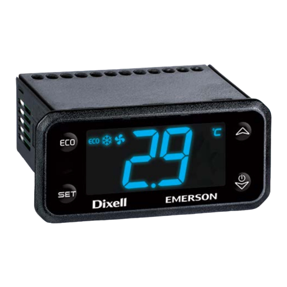
GENERAL DESCRIPTION
The XRB06CX, format 32 x 74 x 60 mm, is microprocessor based controller, suitable for applications on
medium or low temperature ventilated refrigerating units. It has three relay outputs to control compressor,
fan, lights or defrost which can be either electrical or reverse cycle (hot gas). The device is also provided
with 2 NTC probe inputs, the first one for temperature control and the second one to be located onto the
evaporator, to control the defrost termination temperature and to control the ventilators. It is also
equipped with a couple of configurable digital inputs.
The XRB07CX has an additional configurable relay.
With the HOTKEY it's possible to program the instrument in a quick and easy way.
3
REGULATION
The regulation is performed according to
the temperature measured
by the
thermostat
probe
with
a
positive
differential from the set point: if the
temperature increases and reaches set
point plus differential the compressor is
started and then turned off when the
temperature reaches the set point value
again.
In case of fault in the thermostat probe the start and stop of the compressor are timed through
parameters CY and Cn.
4
AUTOMATIC SUPER COOLING FUNCTION
This function is used to cool quickly the goods when the cabinet is filled.
Different parameters are used for this function depending on the working mode:
Normal mode will use: 1H, 1S and 1t
Energy Saving mode will use: 2H, 2S, 1t
Here below the parameter description:
-
1H, 2H overheating before activating the super cooling function: (0.0 to 12.0°C; 0 to 21°F) value
added to Set-Point to determine the start temperature of sub-cooling cycle.
-
1S, 2S Subcooling: (0.0 to 12.0°C; 0 to 21°F) value subtracted to Set-Point to determine the end
temperature of sub-cooling cycle.
-
1t maximum duration for super cooling function: 0 to 99 min
If the temperature is higher than SET+HY+1H or SET_ES+HYE+2H, the super cooling function starts and
the compressor is not stopped till the temperature is 1S or 2S degrees below the set point SET or
SET_ES. To disable this function set 1S, 2S=0.
1592033060 - XRB06-07CH GB r1.0 12.02.2018.docx
5
DEFROST
Two defrost modes are available through the td parameter:
td=EL defrost through electrical heater (compressor OFF)
td=in hot gas defrost (compressor ON).
Other parameters are used to control the interval between defrost cycles (id), its maximum length (Md)
and two defrost modes: timed or controlled by the evaporator's probe. At the end of defrost dripping time
is started, its length is set in the dt parameter. With dt=0 the dripping time is disabled.
6
FANS
With FC parameter it can be selected the fans functioning:
FC=Cn will switch ON and OFF with the compressor and not run during defrost
FC=on fans will run even if the compressor is off, and not run during defrost
After defrost, there is a timed fan delay allowing for drip time, set by means of the Fd parameter.
FC=Cy fans will switch ON and OFF with the compressor and run during defrost
FC=oY fans will run continuously also during defrost.
An additional parameter FS provides the setting of temperature, detected by the evaporator probe, above
which the fans are always OFF. This is used to make sure circulation of air only if his temperature is
lower than set in FS.
6.1
FANS CYCLICAL ACTIVATION WITH COMPRESSOR OFF
When FC=Cn or CY (fans in parallel to the compressor), by means of the Fn and FF parameters the fans
can carry out on and off cycles even if the compressor is switched off. When the compressor is stopped
the fans go on working for the Fn time. With Fn=0 the fans remain always off, when the compressor is
off.
6.2
FANS AND DIGITAL INPUT
When the digital input is configured as door switch (iF=do) fan and compressor status depends on the
dC parameter value:
dC=no normal regulation
dC=Fn fans OFF
dC=CP compressor OFF
dC=FC compressor and fans OFF
When rd=Y, the regulation restart with door open alarm.
7
AUTOMATIC ENERGY SAVING FUNCTION
FROM
TO
Standard
E.S.
E.S.
Standard
NOTE: the cycles (ES → Standard mode → ES ....) are always operating with iF or 2F=do and Et and
St different from zero.
With Et or St=0 the controller doesn't change the operating mode, and it's possible to pass from the
standard mode to E.S. by using the ECO button or with iF or 2F=ES.
Note: the energy saving status is saved in EEPROM to resume previous operation if a power failure
occurs.
8
FRONT PANEL COMMANDS
To display target set point, in programming mode it selects a parameter or
confirm an operation.
XRB06CH – XRB07CH
CHANGED BY
- Push the ECO button
- Door continuously closed for the Et time
- Push the ECO button
- Controller in ES mode for the St time
-
If the controller is in ES and the door is open more than do time,
the controller restart standard set point.
1/5

Related Manuals for Emerson Dixell XRB06CH


Summary of Contents for Emerson Dixell XRB06CH
- Page 1 DEFROST DIGITAL CONTROLLERS WITH Two defrost modes are available through the td parameter: td=EL defrost through electrical heater (compressor OFF) ENERGY SAVING MANAGEMENT td=in hot gas defrost (compressor ON). Other parameters are used to control the interval between defrost cycles (id), its maximum length (Md) XRB06CH AND XRB07CH and two defrost modes: timed or controlled by the evaporator’s probe.
- Page 2 PARAMETERS (ECO) for light or energy saving mode activation/deactivation REGULATION (UP) In programming mode it browses the parameter codes or increases Differential in standard mode: (0.1 to 25°C; 1 to 45°F) differential for set point used in normal the displayed value. mode.
-
Page 3: Digital Inputs
Temperature alarm delay: (0 to 99 min) time interval between the detection of an alarm ECO key configuration (long pressure): (dE; Li; Au; P2; ES) dE=defrost; Li=light; Au=do condition and alarm signalling. not use; P2=probe P2 value visualisation; ES=energy saving mode Exclusion of temperature alarm at start-up: (0 to 99 min) time interval between the DOWN key configuration (long pressure): (nu;... -
Page 4: Alarm Signalling
13 USE THE HOT KEY 16 CONNECTIONS 13.1 HOW TO PROGRAM THE HOT KEY FROM THE INSTRUMENT 16.1 XRB06CH – 20+8+5A (UPLOAD) Program a controller by using the keypad. When the controller is ON, insert the “Hot Key” and push UP key. The "uP"... - Page 5 Temperature differential forced Parameter code table Read Only - - - 0 to 50°C; 0 to 90°F activation of fans Fans stop temperature -55 to 50°C; -67 to 99°F 50.0°C (*) available only for XRB07CH Fan ON time 0 to 15 min Fan OFF time 0 to 15 min Probe selection for fan management...