Siemens SIMATIC Ident Function Manual
Rfid systems. ident profile, add-on instruction for rockwell systems
Hide thumbs
Also See for SIMATIC Ident:
- System manual (362 pages) ,
- Function manual (142 pages) ,
- Operating manual (80 pages)
Table of Contents
Quick Links
See also:
Function Manual, System Manual
SIMATIC Ident
RFID systems
Ident profile, Add-on instruction for
Rockwell systems
Function Manual
01/2019
C79000-G8976-C410-03
___________________
Preface
___________________
Introduction
___________________
Description
Configuring with Studio 5000
___________________
Logix Designer
___________________
Configuring the instructions
___________________
Error messages
___________________
Appendix
1
2
3
4
5
A
Table of Contents

Related Manuals for Siemens SIMATIC Ident


Summary of Contents for Siemens SIMATIC Ident
- Page 1 ___________________ Preface ___________________ Introduction ___________________ SIMATIC Ident Description Configuring with Studio 5000 ___________________ Logix Designer RFID systems Ident profile, Add-on instruction for ___________________ Rockwell systems Configuring the instructions ___________________ Error messages Function Manual ___________________ Appendix 01/2019 C79000-G8976-C410-03...
- Page 2 Note the following: WARNING Siemens products may only be used for the applications described in the catalog and in the relevant technical documentation. If products and components from other manufacturers are used, these must be recommended or approved by Siemens. Proper transport, storage, installation, assembly, commissioning, operation and maintenance are required to ensure that the products operate safely and without any problems.
-
Page 3: Preface
We reserve the right to make changes to these application examples at any time without prior notice. If there are any deviations between the recommendations provided in these application examples and other Siemens publications – e.g. Catalogs – the contents of the other documents have priority. - Page 4 Preface Ident profile, Add-on instruction for Rockwell systems Function Manual, 01/2019, C79000-G8976-C410-03...
-
Page 5: Table Of Contents
Table of contents Preface ..............................3 Introduction ............................. 7 Description .............................. 9 Area of application and features ....................9 Functions of the instructions ....................10 Configuring with Studio 5000 Logix Designer ..................11 Configuring with Studio 5000 Logix Designer ................. 11 Integrating modules into Studio 5000 Logix Designer ............ - Page 6 Table of contents 4.5.5 RESET instructions ........................ 53 4.5.5.1 Reset_RF68xR ........................53 4.5.5.2 Reset_MV ..........................53 4.5.5.3 Reset_RF200 ......................... 54 4.5.5.4 Reset_RF300 ......................... 55 4.5.5.5 Reset_RF600 ......................... 56 4.5.5.6 Reset_Univ ..........................57 Programming the Ident profile ....................58 4.6.1 Structure of the Ident profile ....................58 4.6.2 Assigning parameters for the instruction ................
-
Page 7: Introduction
Siemens AG. Naming of the functions The elements typically referred to as "blocks" at Siemens are called "Add-On Instructions" at Rockwell. In the remainder of this manual the typical Rockwell names are used. Ident profile, Add-on instruction for Rockwell systems... - Page 8 Siemens’ products and solutions undergo continuous development to make them more secure. Siemens strongly recommends that product updates are applied as soon as they are available and that the latest product versions are used. Use of product versions that are no longer supported, and failure to apply the latest updates may increase customers’...
-
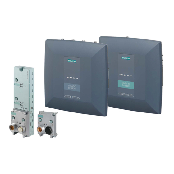
Page 9: Description
Description Area of application and features The Ident profile can be used in Rockwell controllers with an Ethernet/IP interface. The modules can be configured using the "Studio 5000 Logix Designer" or "RSLogix 5000" programs. Figure 2-1 Configurable module: RFID 181EIP and RF680R/RF685R Ident profile, Add-on instruction for Rockwell systems Function Manual, 01/2019, C79000-G8976-C410-03... -
Page 10: Functions Of The Instructions
Description 2.2 Functions of the instructions Functions of the instructions The "Ident_Profile" instruction serves as the communication interface between an Ident device (e.g. RFID 181EIP) and the user program. The instruction supports the following functions: ● Configuration ● Editing commands ●... -
Page 11: Configuring With Studio 5000 Logix Designer
The modules must be integrated into the Studio 5000 Logix Designer via an EDS file. The EDS file is contained in the Add-On Instructions library. You can find the latest file on the pages of the Siemens Industry Online Support (https://support.industry.siemens.com/cs/ww/en/ps/14971/dl). With RF68xR readers, the file is also stored on the readers themselves and on the DVD that is supplied with the RF68xR readers. -
Page 12: Creating A Studio 5000 Logix Designer Project
Configuring with Studio 5000 Logix Designer 3.3 Creating a Studio 5000 Logix Designer project Creating a Studio 5000 Logix Designer project The modules can be integrated into Rockwell automation systems using Studio 5000 Logix Designer. The connection is via Ethernet/IP. Following this, you can configure the RF68xR reader using WBM while you control the work with the module using the add-on instructions of Studio 5000 Logix Designer. -
Page 13: Configuring The Instructions
To program Ident systems using the Studio 5000 Logix Designer, you require add-on instructions. You can find the add-on instructions on the DVD supplied with the RF68xR readers or on the pages of the Siemens Industry Online Support (https://support.industry.siemens.com/cs/ww/en/ps/14971/dl). Requirement The Studio 5000 Logix Designer was started and a project was created. -
Page 14: Overview Of The Add-On Instructions
Configuring the instructions 4.2 Overview of the add-on instructions Overview of the add-on instructions To program the various identification systems, a library with add-on instructions is available. The following table provides an overview of the currently available add-on instructions. Table 4- 1 Overview of the add-on instructions Position Symbolic name... - Page 15 Configuring the instructions 4.2 Overview of the add-on instructions Position Symbolic name Description Data types System data types IID_CMD_STRUCT Data type for the Ident profile for setting the command parameters. IID_DATA_RF68xR Data type for parameter data for the reader / communication module and data for synchro- IID_DATA_RFID181EIP nizing the instructions for all read points of a...
-
Page 16: General Structure Of The Add-On Instructions
Configuring the instructions 4.3 General structure of the add-on instructions General structure of the add-on instructions Form of the instruction as an example The following graphic shows an example of a instruction with input and output parameters as they exist in the same way in all instructions. Figure 4-1 Example instructions Description of the parameters... -
Page 17: Project Preparation
Configuring the instructions 4.4 Project preparation Project preparation To prepare the project and configure the individual instructions, you must first perform the following steps: 1. Configure the parameter instruction ("Param_*") and address the modules. 2. Assign parameters to the "RESET" instruction. You can then configure the required instructions accordingly. -
Page 18: Configuring The Reset Instruction
Configuring the instructions 4.4 Project preparation Feed for instruction "Param_*" Proceed as follows to create the "Param_*" instruction: 1. Drag the instruction from the "Controller Organizer" into the project. 2. Create a instance variable. 3. Create a global variable for the "CONFIGDATA" parameter. The variable of the data type "IID_DATA_*". - Page 19 Configuring the instructions 4.4 Project preparation Feed for instruction "RESET*" The procedure is described below using a specific "WRITE-CONFIG" instruction. The procedure for using the Ident profile with a "WRITE-CONFIG" command is identical. Proceed as follows to create the "Reset_*" instruction: 1.
-
Page 20: Programming Add-On Instructions
Configuring the instructions 4.5 Programming add-on instructions 11.When using the RF68xR reader: If applicable, select the "Connected" and "Large Connection" check boxes if they were activated beforehand in step 7. 12.Select the relevant input word of the reader/CM for the parameter "STATUS_WORD" (:I.Data[0]). - Page 21 Configuring the instructions 4.5 Programming add-on instructions Instruction "Param_RFID181EIP" Figure 4-3 Instruction "Param_RFID181EIP" Table 4- 3 Explanation for the instruction "Param_RFID181EIP" Parameter Data type Default values Description MOBY_MODE SINT MOBY mode for the connected Ident system on the channels of the RFID 181EIP: 0x05 = RF200/RF300/RF600;...
-
Page 22: Basic Instructions
Configuring the instructions 4.5 Programming add-on instructions 4.5.2 Basic instructions 4.5.2.1 Read The "Read" instruction reads the user data from the transponder and enters this in the "IDENT_DATA" buffer. The physical address and the length of the data are transferred using the "ADDR_TAG"... -
Page 23: Write
Configuring the instructions 4.5 Programming add-on instructions Parameter Data type Default values Description EPCID_UID SINT[62] Buffer for up to 62 bytes EPC-ID, 8 bytes UID or 4 bytes handle ID. 2 - 62-byte EPC-ID is entered at • the start of the buffer (length is set by "LEN_ID") 8-byte UID is entered at the start •... - Page 24 Configuring the instructions 4.5 Programming add-on instructions Table 4- 5 Explanation for the instruction "Write" Parameter Data type Default values Description ADDR_TAG DINT 0x00 Physical address on the transponder where the write starts. You will find more information on addressing in the section "Transponder addressing (Page 96)".
-
Page 25: Read_Mv
Configuring the instructions 4.5 Programming add-on instructions 4.5.2.3 Read_MV The "Read_MV" instruction reads the read result of an optical reader. The "Read" instruction must be used to read the configuration. The length of the data to be read is calculated automatically by the instruction based on the length of the created receive buffer. -
Page 26: Set_Mv_Program
Configuring the instructions 4.5 Programming add-on instructions 4.5.2.4 Set_MV_Program Using the "Set_MV_Program" instruction, you can change the program in a camera. The required program number is transferred using the "PROGRAM" parameter. Figure 4-7 Instruction "Set_MV_Program" Table 4- 7 Explanation for the instruction "Set_MV_Program" Parameter Data type Default values... -
Page 27: Extended Instructions
Configuring the instructions 4.5 Programming add-on instructions 4.5.3 Extended instructions 4.5.3.1 Config_Upload/-_Download Using the "Config_Upload" and "Config_Download" instructions, you can read ("Config_Upload") or write ("Config_Download") the configuration of the RFID181 EIP reader and RF68xR reader communications modules connected to this controller. The configuration data is not interpretable data. - Page 28 Configuring the instructions 4.5 Programming add-on instructions Figure 4-8 Instruction "Config_Upload" Table 4- 9 Explanation for the instruction "Config_upload" Parameter Data type Default value Description IDENT_DATA SINT[10] Data buffer for configuration data. The real length of the data depends on the complexity of the configuration and the firmware version of the read- er.
-
Page 29: Inventory
Configuring the instructions 4.5 Programming add-on instructions Figure 4-9 Instruction "Config_download" Table 4- 10 Explanation for the instruction "Config_download" Parameter Data type Default value Description IDENT_DATA SINT[10] Data buffer for configuration data. The real length of the data depends on the complexity of the configuration and the firmware version of the read- er. - Page 30 Configuring the instructions 4.5 Programming add-on instructions Special features of the RF68xR reader Note that the length of the data buffer ("IDENT_DATA") must correspond to at least the length of the maximum expected data. If more transponders are identified and data read out than have space in the assigned buffer length of "IDENT_DATA", the data of these transponders is lost.
- Page 31 Configuring the instructions 4.5 Programming add-on instructions Figure 4-10 Instruction "Inventory" Table 4- 11 Explanation for the instruction "Inventory" Parameter Data type Default values Description ATTRIBUTE SINT 0x00 Selecting the status mode: RF620R, RF630R: 0x82 (read out • next data record), 0x83, 0x85, 0x90, 0x91, 0x92 RF68xR: 0x80, 0x81, 0x86, 0x87 •...
- Page 32 Configuring the instructions 4.5 Programming add-on instructions Parameter Data type Default values Description NUMBER_TAGS Number of transponders in the anten- na field LEN_DATA 0x00 Length of the valid data During command processing = 0 Result for RF68xR The number of "TAG_DATA[x]" elements of the data types of the ATTRIBUTE "0x80" and "0x81"...
- Page 33 If required, you can create these data types. You can find information on this in the manual "Ident profile and Ident blocks, standard function for Ident systems (https://support.industry.siemens.com/cs/ww/en/ps/14971/man)". Ident profile, Add-on instruction for Rockwell systems Function Manual, 01/2019, C79000-G8976-C410-03...
-
Page 34: Read_Epc_Mem
Configuring the instructions 4.5 Programming add-on instructions 4.5.3.3 Read_EPC_Mem The "Read_EPC_Mem" instruction reads data starting at address 4 from the EPC memory of the RF600 transponder. Access is to bank 1 as of the start address 4. The length of the EPC memory to be read out is specified by the "LEN_DATA"... -
Page 35: Read_Tid
Configuring the instructions 4.5 Programming add-on instructions 4.5.3.4 Read_TID The "Read_TID" instruction reads data from the TID memory area (Tag Identification Memory Bank) of the RF600 transponder. The length of the TID to be read is specified by the "LEN_DATA" parameter. The length of the TID varies depending on the transponder and can be found in the transponder data sheet. -
Page 36: Read_Uid
Configuring the instructions 4.5 Programming add-on instructions 4.5.3.5 Read_UID The "Read_UID" instruction reads the UID of an HF transponder. The UID always has a fixed length of 8 bytes. Figure 4-13 Instruction "Read_UID" Table 4- 16 Explanation for the instruction "Read_UID" Parameter Data type Default value... - Page 37 Configuring the instructions 4.5 Programming add-on instructions Table 4- 17 Explanation for the instruction "Set_Ant_RF300" Parameter Data type Default values Description ANTENNA BOOL 0 = turn antenna off 1 = turn antenna on Set_Ant_RF600 Figure 4-15 Instruction "Set_Ant_RF600" Table 4- 18 Explanation for the instruction "Set_Ant_RF600"...
-
Page 38: Set_Param
Configuring the instructions 4.5 Programming add-on instructions 4.5.3.7 Set_Param Using the "Set_Param" instruction, you can change UHF parameters during runtime (e.g. the antenna power). Note Settings saved only temporarily Note that the parameters in the "Set_Param" instruction are only stored temporarily. If the power for the reader is interrupted, the stored values are lost and must be set again. - Page 39 Configuring the instructions 4.5 Programming add-on instructions All parameters listed in the table below are valid for RF68xR. Table 4- 20 Parameter values PARMID PARMID Parameter VALUE (hex) (ASCII) 0x41315057 A1PW Antenna 01: Radiated power Range of values: 0.5 ... 33 Increment: 0.25 0x41325057 A2PW...
- Page 40 Configuring the instructions 4.5 Programming add-on instructions PARMID PARMID Parameter VALUE (hex) (ASCII) 0x52364353 R6CS Modulation scheme Range of values: 32, 33, 34, 35, 37, Modulation scheme of the read point Specification of which transponder types are identified (ISO 18000-63/- 62).
-
Page 41: Write_Epc_Id
Configuring the instructions 4.5 Programming add-on instructions 4.5.3.8 Write_EPC_ID The "Write_EPC_ID" instruction overwrites the EPC-ID of the RF600 transponder and adapts the length of the EPC-ID in the memory of the transponder. The new EPC-ID length to be written is specified with the "LEN_ID_NEW" parameter and the previous EPC-ID is specified using the "LEN_ID"... -
Page 42: Write_Epc_Mem
Configuring the instructions 4.5 Programming add-on instructions 4.5.3.9 Write_EPC_Mem The "Write_EPC_Mem" instruction overwrites the EPC memory of the RF600 transponder starting at address 4. The length of the EPC memory to be overwritten is specified by the "LEN_DATA" parameter. Figure 4-18 Instruction "Write_EPC_Mem"... -
Page 43: Advancedcmd
Configuring the instructions 4.5 Programming add-on instructions 4.5.3.10 AdvancedCMD Using the "AdvancedCmd" instruction, every command can be executed including commands not represented by other instructions. This general structure can be used for all commands and is intended only for trained users. This instruction gives you the option of sending the command as a chained command. -
Page 44: Status Instructions
Configuring the instructions 4.5 Programming add-on instructions 4.5.4 Status instructions 4.5.4.1 Reader_Status The "Reader_Status" instruction reads status information from the reader or communications module ("CM configuration_1" module) For the various reader families, there are different status modes that you can select using the "ATTRIBUTE" parameter. Figure 4-20 Instruction "Reader_Status"... - Page 45 Configuring the instructions 4.5 Programming add-on instructions Results Apply the correct data type that is assigned to the ATTRIBUTE value at the "IDENT_DATA" input of the instruction so that the data can be correctly interpreted. Only an Array of Byte can be created at the "Ident Data"...
- Page 46 Configuring the instructions 4.5 Programming add-on instructions Table 4- 27 ATTRIBUTE "0x89" (data type "IID_READSTAT_89_RF68xR") compatible with RF68xR Name Type Comment status info SINT SLG status mode(Subcommand) hardware version SINT Version of hardware firmware version SINT[4] Version of firmware config ID DINT Unix timestamp inventory_status...
- Page 47 Configuring the instructions 4.5 Programming add-on instructions Table 4- 29 ATTRIBUTE "0x88" (data type "IID_READSTAT_88_RF600") Name Type Comment status info SINT SLG status mode(Subcommand) hardware SINT Type of hardware hardware version Version of hardware reserved word1 Reserved firmware SINT Type of firmware firmware version HB SINT Version of firmware (High-Byte)
- Page 48 Configuring the instructions 4.5 Programming add-on instructions Name Type Comment reserved byte4 SINT Reserved error command1 Last command (has lead to error code) "last error" error command2 Last command (has lead to error code) "last error" error command3 Last command (has lead to error code) "last error" reserved word5 Reserved reserved_array_byte...
-
Page 49: Tag_Status
Configuring the instructions 4.5 Programming add-on instructions The identifiers of the status modes correspond to the following identifiers in the other manuals: 0x81 ≙ 0x01 0x82 ≙ 0x02 0x83 ≙ 0x03 0x85 ≙ 0x05 0x87 ≙ 0x07 0x88 ≙ 0x08 0x90 ≙... - Page 50 Configuring the instructions 4.5 Programming add-on instructions Table 4- 31 Explanation for the instruction "Tag_Status" Parameter Data type Default values Description ATTRIBUTE SINT 0x00 Identifier of the status modes / possi- ble entries: RF200: 0x83 • RF300: 0x04, 0x82, 0x83 •...
- Page 51 Configuring the instructions 4.5 Programming add-on instructions Table 4- 33 ATTRIBUTE "0x82" ("IID_TAG_STATUS_82_RF300" data type) Name Type Comment reserved SINT status info SINT MDS status mode SINT[8] SINT Magnetic flux density: correlation between limit-value SINT Error counter passive: distortion without communication SINT Error counter active: distortion during communication ANWZ...
- Page 52 Configuring the instructions 4.5 Programming add-on instructions Table 4- 36 ATTRIBUTE "0x85" ("IID_TAG_STATUS_85_RF600" data type) Name Type Comment status info SINT MDS status mode antenna SINT Antenna which has observed the MDS channel SINT Channel SINT[8] DT_glimpsed_1 SINT Time elasped between acknowledgement and first read in [ms]1 Highbyte DT_glimpsed_2 SINT...
-
Page 53: Reset Instructions
Configuring the instructions 4.5 Programming add-on instructions 4.5.5 RESET instructions The reset instructions described in this section are required if you want to operate the RF68xR readers or the RFID181 EIP communication modules with a Rockwell controller. Remember that the default value will be used automatically if you do not select a value manually. -
Page 54: Reset_Rf200
Configuring the instructions 4.5 Programming add-on instructions Table 4- 37 Explanation for the instruction "Reset_MV" Parameter Data type Default values Description PROGRAM SINT Program selection B#16#0: Reset without program • selection or in the case of diagnos- tics, the error code for "IN_OP = 0" is shown at the "STATUS"... -
Page 55: Reset_Rf300
Configuring the instructions 4.5 Programming add-on instructions 4.5.5.4 Reset_RF300 Figure 4-25 Instruction "Reset_RF300" Table 4- 39 Explanation for the instruction "preset_RF300" Parameter Data type Default values Description TAG_CONTROL SINT Presence check 0 = Off • 1 = on • 4 = presence (antenna is off. The •... -
Page 56: Reset_Rf600
Configuring the instructions 4.5 Programming add-on instructions 4.5.5.5 Reset_RF600 Note that this reset instruction is only compatible with the RF620R and RF630R readers. Figure 4-26 Instruction "preset_RF600" (RF620R/RF630R) Table 4- 40 Explanation for the instruction "preset_RF600" (RF620R/RF630R) Parameter Data type Default values Description TAG_CONTROL... -
Page 57: Reset_Univ
Configuring the instructions 4.5 Programming add-on instructions Parameter Data type Default values Description UID_HANDLE BOOL False Meaning of the UID in the command: True = Handle ID, only the least signif- icant 4 bytes of the UID are evaluated; False = UID/EPC-ID with a length of 8 bytes BLACK_LIST BOOL... -
Page 58: Programming The Ident Profile
Configuring the instructions 4.6 Programming the Ident profile Table 4- 42 Structure of the "PARAM" parameter Byte 2...5 7...8 13...14 Value 0x04 0x00 0x0A 0x00 scan- param option_ dis- No. of field_ field_ ning_ tance_ tran- time limiting spond- control time Programming the Ident profile 4.6.1... - Page 59 Configuring the instructions 4.6 Programming the Ident profile Figure 4-28 The input parameters of the Ident profile Note Working with multiple channels If you work with several channels, you must ensure that for each channel, the block is called with a separate instance DB. Ident profile, Add-on instruction for Rockwell systems Function Manual, 01/2019, C79000-G8976-C410-03...
- Page 60 Configuring the instructions 4.6 Programming the Ident profile Interface description Table 4- 43 Input parameter Input parameter Data type Default value Meaning HW_CONNECT HW_CONNECT Global parameter of type "IID_HW_CONNECT" to address the communication module and reader and to synchronize the blocks. This parameter is located in the variables of the type "IID_DATA_ *".
- Page 61 Configuring the instructions 4.6 Programming the Ident profile Table 4- 44 Output parameter Output parameter Data type Default value Meaning DONE BOOL FALSE TRUE = Command was executed free of errors. ERROR BOOL FALSE TRUE = Error was detected. The error is output in the "STATUS" parameter. The bit is reset automatically when a new command is started.
-
Page 62: Assigning Parameters For The Instruction
Configuring the instructions 4.6 Programming the Ident profile Output parameter Data type Default value Meaning UIN0 BOOL FALSE With RFID readers, the number of transponders in the an- tenna field is indicated. UIN0 ... UIN3 can be interpreted as UIN1 BOOL FALSE binary values. - Page 63 Configuring the instructions 4.6 Programming the Ident profile ● IDENT_DATA_RXREF ● HW_CONNECT ● MSG_READ ● MSG_WRITE ● STATUS_WORD ● CONTROL_WORD Example of parameter assignment IdentProfile Create a instance variable. CMDREF Assign a variable to the "CMDREF" parameter. This variable has the "IID_CMD_STRUCT[10]"...
-
Page 64: Data Structure Of The Ident Profile
Configuring the instructions 4.6 Programming the Ident profile The element numbers are assigned as follows: ● Element 0 for channel 1: ...Data[0] ● Element 1 for channel 2: ...Data[1] Figure 4-30 Automatically created input and output variables MSG_WRITE and MSG_READ Assign a "MESSAGE"... - Page 65 Configuring the instructions 4.6 Programming the Ident profile Figure 4-31 Data structure example of the Ident profile Ident profile, Add-on instruction for Rockwell systems Function Manual, 01/2019, C79000-G8976-C410-03...
-
Page 66: Commands Of The Ident Profile
Configuring the instructions 4.6 Programming the Ident profile Explanation of the data structure example ● CMDREF[0]: Command "WRITE-CONFIG", OFFSETBUFFER = 0 At the "CMDREF[0]" point you need to set the "WRITE-CONFIG" command so that the "INIT/Reset" is correctly executed. ● CMDREF[1]: Command "WRITE", OFFSETBUFFER = 15 ●... - Page 67 Configuring the instructions 4.6 Programming the Ident profile Command Command code Parameters used Description ASCII 0x65 OFFSETBUFFER, Transfers further commands not specified in the EPCID_UID, LEN_ID, standard profile. To this end, a corresponding data LEN_DATA structure is defined in the send data buffer for each command.
-
Page 68: Command Structure
Configuring the instructions 4.6 Programming the Ident profile 4.6.4.2 Command structure Before you can start a command with "EXECUTE" or "INIT", you need to define the command. To allow simple definition of a command, the command buffer "CMDREF" was created using the "IID_CMD_STRUCT" data type. In the command buffer, you have 10 areas available in which commands can be programmed. - Page 69 Configuring the instructions 4.6 Programming the Ident profile Parameter Data type Default val- Description EXT_UHF STRUCT Structure for additional parameters (RF680R/RF685R only) LEN_ID SINT Length of the valid data in the "EPCID_UID" field. MEM_BANK SINT Memory bank on the transponder 0x00 = RESERVED •...
-
Page 70: Commands
Configuring the instructions 4.6 Programming the Ident profile 4.6.4.3 Commands All relevant parameters and parameter values for the individual commands are listed below. Parameters that are not listed receive the default value specified in the previous section. Table 4- 47 PHYSICAL-READ Parameter Value / description... - Page 71 Configuring the instructions 4.6 Programming the Ident profile Table 4- 48 PHYSICAL-WRITE Parameter Value / description 0x71 OFFSETBUFFER Offset in the "TXREF" send buffer LEN_DATA Length of the data to be written RF300 Gen1: Max. 57,085 bytes per write operation ADDR_TAG Address on the transponder CHAINED...
- Page 72 Configuring the instructions 4.6 Programming the Ident profile Table 4- 50 TAG-STATUS Parameter Value / description 0x73 OFFSETBUFFER Offset in the "RXREF" receive buffer ATTRIBUTES Identifier of the status modes / possible entries: RF200: 0x83 • RF300 (RF300T): 0x04, 0x82 •...
- Page 73 Configuring the instructions 4.6 Programming the Ident profile Table 4- 51 INVENTORY Parameter Value / description 0x69 OFFSETBUFFER Offset in the "RXREF" receive buffer ATTRIBUTES Identifier of the status modes / possible entries: RF68xR: 0x80 ≙ inventory with brief transponder information •...
- Page 74 Configuring the instructions 4.6 Programming the Ident profile Parameter Value / description INVENTORY_DUR_UNIT Only for 0x80 and 0x81: Unit for "DURATION" 0x00 ≙ time [ms] • 0x01 ≙ inventories • 0x02 ≙ number of transponders that achieve the "Observed" state •...
- Page 75 Configuring the instructions 4.6 Programming the Ident profile Table 4- 54 Explanation of the structure of the data attachment for the "FORMAT" command Byte Description Bytes 1...8 Reserved for security code (must be assigned "0", since SIMATIC RFID has had no code previously) Byte 9 Length of the following data, here 6...
- Page 76 Configuring the instructions 4.6 Programming the Ident profile Table 4- 56 PUT (not with RF68xR) Parameter Value / description 0x65 OFFSETBUFFER Offset in the "TXREF" send buffer LEN_DATA Length of the parameter data to be sent TXREF Parameter data to be written Table 4- 57 Data structure of the PUT command Put_SET_ANT...
- Page 77 Configuring the instructions 4.6 Programming the Ident profile Table 4- 58 WRITE-ID (only with RF68xR) Parameter Value / description 0x67 OFFSETBUFFER Offset in the "TXREF" send buffer EPCID_UID Previous EPC-ID 0x00 ≙ unspecified single tag access LEN_ID Length of the previous EPC-ID (2-62 bytes) 0x00 ≙...
- Page 78 Configuring the instructions 4.6 Programming the Ident profile Table 4- 61 EDIT-BLACKLIST (only with RF68xR) Parameter Value / description 0x7A EDIT_BLACKLIST_MODE 0x00 ≙ add EPC-ID • 0x01 ≙ Add all "Observed" transponders • 0x02 ≙ Delete EPC-ID • 0x03 ≙ delete all •...
- Page 79 Configuring the instructions 4.6 Programming the Ident profile Table 4- 64 READ-CONFIG Parameter Value / description 0x61 OFFSETBUFFER Offset in the "RXREF" receive buffer RXREF Read reset parameters Table 4- 65 WRITE-CONFIG Parameter Value / description 0x78 OFFSETBUFFER Offset in the "TXREF" send buffer LEN_DATA Length of the parameter data CONFIG...
- Page 80 Configuring the instructions 4.6 Programming the Ident profile Structure of the configuration data attachment of "WRITE-CONFIG" For RF68xR: ● When CONFIG = 0x01: Reset_Reader; LEN_DATA = 0x00 ● When CONFIG = 0x03: When replacing a module, it is possible to read all the configuration data from the CM/reader and to store it on the controller.
- Page 81 Configuring the instructions 4.6 Programming the Ident profile Table 4- 67 Bytes of the "PARAM" parameter Byte Value RFID system Meaning Byte 9 scanning_ RF200, 0x00 (reserved) time RF300 RF600 "scanning_time" describes the radio profile according to EPC Global. Set the cor- rect standard according to the country in which you want to operate the reader.
- Page 82 Configuring the instructions 4.6 Programming the Ident profile Byte Value RFID system Meaning Value of bit 3 ... 0 Value Operating Description of bit 3 mode ... 0 0x00 Reserved reserved for the setting with the switch or GSD pa- rameter assignment 0x01 MOBY I...
- Page 83 RF200 0x00 (reserved) limiting RF300 Note: This parameter is intended for trained users. Siemens recommends that (only untrained users use the default value. RF380R) Readers of the 1st generation: With this parameter you can change the transmit power (output power) of the RF380R reader of the 1st generation (6GT2801- 3AB10).
- Page 84 Configuring the instructions 4.6 Programming the Ident profile Byte Value RFID system Meaning Value RF630R RF620R RF620R transmit power radiated power (internal antenna) transmit power ETSI CMIIT dBm / (mW) dBm / dBm / dBm / (mW) dBm / (mW) (mW) (mW) EIRP...
- Page 85 Configuring the instructions 4.6 Programming the Ident profile Byte Value RFID system Meaning ScanningMode (relevant for multitag mode): 0x00 = Normal multitag mode without ScanningMode (including "re- • peat_command") 0x01 = ScanningMode • Unspecified read commands (UID = 0x00) are also accepted by the CM/reader if there is more than one transponder in the antenna field.
- Page 86 Configuring the instructions 4.6 Programming the Ident profile Byte Value RFID system Meaning 0x20 ISO 14443 e.g. MDS E600, E611, E623, E624 (MOBY E, E6xx) 0x31 General mode Activation of the so-called "General mode" for pro- (ISO, RF300, cessing the transponder types RF300, ISO 15693 and MOBY E) ISO 14443.
-
Page 87: Expanded Commands For Optical Reader Systems (Mv400/Mv500)
Configuring the instructions 4.6 Programming the Ident profile Byte Value RFID system Meaning 0x00: Default; the channels of the reader are used in four channel mode. Note: The setting "0x0F" is identical to "0x00". With bits 0 to 3 of the "field_ON_time" byte, a channel (frequency) plan can be created for the situation in which several readers are operated in close proximity. - Page 88 Configuring the instructions 4.6 Programming the Ident profile The "PHYSICAL-WRITE" command The optical reader systems MV400/MV500 have further commands that can be transferred with the "PHYSICAL-WRITE" command. Table 4- 70 PHYSICAL-WRITE OFFSET ADDR_TA LEN_DATA TXREF BUFFER 0x71 Offset in 0x0000 Length of data to be sent to the read- Sub command with data to be sent to the read- er.
- Page 89 Configuring the instructions 4.6 Programming the Ident profile Table 4- 73 Command data area "TXREF" command identifier 0x03 (write match string) Address Value Meaning 0x0000 0x03 Command identifier "Write match string" 0x0001 0x00...0xFF Match string length high byte 0x0002 0x00...0xFF Match string length low byte 0x0003 1st character of the match string...
- Page 90 Configuring the instructions 4.6 Programming the Ident profile Table 4- 78 Command data area "TXREF" command identifier 0x08 (set Digital Out) Address Value Meaning 0x0000 0x08 Command identifier "Set Digital Out" 0x0001 0x01...0x04 Number of the logical external signal. Corre- sponds to "EXT_1", "EXT_2", "EXT_3"...
-
Page 91: Effect Of The Commands
Configuring the instructions 4.6 Programming the Ident profile The "PHYSICAL-READ" command The "PHYSICAL-READ" command is used for the following functions: ● Reading codes ● Follow-on command after "activate read program number" for reading out the program number ● Follow-on command after "activate read match string" for reading out the match string Table 4- 79 PHYSICAL-READ OFFSET... -
Page 92: Editing Commands
Configuring the instructions 4.6 Programming the Ident profile 4.6.4.6 Editing commands Follow the steps below to edit the commands: 1. Write the "CMDREF" (SINT[n]) parameter with the required commands. The content of "CMDREF" = [0] is reserved for initialization. It is executed when the "INIT" input of the Ident profile is set and "CMDSEL"... -
Page 93: Parameter Assignment For Starting Up And Restarting
Configuring the instructions 4.6 Programming the Ident profile 4.6.4.7 Parameter assignment for starting up and restarting The communications module and the reader are restarted by setting the "INIT" parameter. With the parameter, the CM or the reader and the Ident profile are reassigned parameters and synchronized. - Page 94 Configuring the instructions 4.6 Programming the Ident profile Command Command code Description ASCII INVENTORY 0x69 Requests a list of all currently accessible transpond- ers within the antenna range. FORMAT 0x66 Initializes the transponder. 0x65 Transfers further commands not specified in the standard profile.
-
Page 95: Digital Inputs/Outputs
Configuring the instructions 4.7 Digital inputs/outputs If several commands are executed in the chain for which data is returned, the position of the data in the receive buffer "RXREF" can be set for each individual command using the "IID_CMD_STRUCT[x].OFFSETBUFFER" parameter. Note "IID_CMD_STRUCT[0]"... -
Page 96: Transponder Addressing
Configuring the instructions 4.8 Transponder addressing Transponder addressing Addressing Addressing of the transponders is linear from address "0x0000" (or the specified start address) to the end address. The CM or reader automatically recognizes the size of the memory on the transponder. If the end address on the transponder is exceeded, you receive an error message. - Page 97 Configuring the instructions 4.8 Transponder addressing System Addressing 16-bit hexadecimal number Start address 0xFFF0 Length 0x0008 Address space of the transponder versions for RF300 System Addressing 16-bit hexadecimal number RF300 20 bytes of data memory (EEPROM) R/W or OTP memory (EEPROM) (The EEPROM user memory for RF300 can be used either as R/W memory or as an OTP memory (see RF300 system manual)) Start address...
- Page 98 Configuring the instructions 4.8 Transponder addressing System Addressing 16-bit hexadecimal number Start address 0xFF00 End address 0xFF13 R/W memory (FRAM) Start address 0x0000 End address 0xFEFC ID-Nr.: (fixed-coded; can only be output as a whole) Start address 0xFFF0 Length 0x0008 RF300: General notes on the meaning of the OTP memory RF300 transponders and ISO transponders have a memory area that can be protected against overwriting.
- Page 99 Configuring the instructions 4.8 Transponder addressing RF300: Address mapping of OTP memory on the RF300 transponder R/W EEPROM memory and OTP memory is only available once on the transponder. The following table shows the mapping of addresses on the transponder. Data can be read via the R/W address or the OTP address.
- Page 100 Configuring the instructions 4.8 Transponder addressing Address space of the transponder versions for RF600 Tags Chip type User RESERVED Special [hex] (read only) (passwords) Area / Area / length Access Area / length Area / length KILL-PW Lock func- length tion (max.
- Page 101 Configuring the instructions 4.8 Transponder addressing Tags Chip type User RESERVED Special [hex] (read only) (passwords) Area / Area / length Access Area / length Area / length KILL-PW Lock func- length tion (max. and default) RF680T NXP G2XM 00 - 3F FF00-FF1D / 240 read/ FFC0-FFC7...
- Page 102 Configuring the instructions 4.8 Transponder addressing Ident profile, Add-on instruction for Rockwell systems Function Manual, 01/2019, C79000-G8976-C410-03...
-
Page 103: Error Messages
Error messages Structure of the "STATUS" output parameter There is always an error status in the "Ident profile" instruction if the output parameter "ERROR = TRUE" is set. The error can be analyzed (decoded) using the "STATUS" output parameter. The "STATUS" output parameter is made up of the following 4 bytes: Table 5- 1 Bytes of the "STATUS"... -
Page 104: Errors From The Communications Module/Reader
Error messages 5.2 Errors from the communications module/reader Errors from the communications module/reader The causes of these errors can, for example, be as follows: ● Errors have occurred in communication between the CM and the reader or between the reader and the transponder. ●... - Page 105 Error messages 5.2 Errors from the communications module/reader Error mes- Description sage (hex) 0xE1FE84 General transponder error 0xE1FE85 The transponder has too little power to execute the command. 0xE2FE01 Field disturbance on reader • Reader is receiving interference pulses from the environment. –...
- Page 106 Error messages 5.2 Errors from the communications module/reader Error mes- Description sage (hex) 0xE2FE88 General radio protocol error 0xE4FE01 Short circuit or overload of the 24 V outputs The reader is using too much current. • The reader cable is causing a short-circuit. •...
- Page 107 Error messages 5.2 Errors from the communications module/reader Error mes- Description sage (hex) 0xE4FE8C Communication error between Ident profile and communications module. Handshake error. • – UDT of this communications module is overwritten by other program sections – Check parameter settings of communications modules in the UDT –...
- Page 108 Error messages 5.2 Errors from the communications module/reader Error mes- Description sage (hex) 0xE5FE0B Incorrect sequence of acknowledgement frames (TDB / DBN) 0xE5FE0C Synchronization error (incorrect increment of AC_H / AC_L and CC_H / CC_L in the cyclic control word). "INIT"...
- Page 109 Error messages 5.2 Errors from the communications module/reader Error mes- Description sage (hex) 0xE6FE85 Reserved 0xE6FE86 The inventory command failed. 0xE6FE87 Read access to the transponder has failed. 0xE6FE88 Write access to the transponder has failed. 0xE6FE89 Writing the EPC-ID on the transponder has failed. 0xE6FE8A Enabling write protection on the transponder has failed.
-
Page 110: Errors From Ethernet/Ip
Error messages 5.3 Errors from Ethernet/IP Errors from Ethernet/IP The transport layer of the bus system being used (Ethernet/IP) is signaling an error. For precise troubleshooting and analysis, a tracer can be useful. For Ethernet/IP, the open source software "Wireshark" can be used. The system diagnostics of Ethernet/IP can provide further information about the cause of the error. -
Page 111: Warnings
Error messages 5.4 Warnings Warnings Byte 3 of the "STATUS" output parameter indicates warnings if byte 0 of the "STATUS" (instruction numbers) has the value "Fxh" or "Dxh". Table 5- 3 Possible warnings when working with the Ident profile Bytes 0...2 Byte 3 Meaning FxFExxh... - Page 112 Error messages 5.4 Warnings Ident profile, Add-on instruction for Rockwell systems Function Manual, 01/2019, C79000-G8976-C410-03...
-
Page 113: Appendix
Appendix Internal status parameter Status variables Every Ident block has status outputs to allow a suitable reaction in the user program if an error occurs and to simplify error diagnostics on the device. In addition to this, every Ident block has a time stamp and an error memory to be able to better understand previous problems. - Page 114 Appendix A.1 Internal status parameter Further status variables exist in the "IID_HW_CONNECT" variable. Table A- 2 Status variables in "IID_HW_CONNECT" Name Data type Description STATUS_IN_WORK BOOL Command is currently being executed True = a block or the Ident profile is •...
-
Page 115: Service & Support
Service & Support Industry Online Support In addition to the product documentation, the comprehensive online information platform of Siemens Industry Online Support at the following Internet address: Link 1: (https://support.industry.siemens.com/cs/de/en/) Apart from news, there you will also find: ● Project information: Manuals, FAQs, downloads, application examples etc. - Page 116 Appendix A.2 Service & Support Ident profile, Add-on instruction for Rockwell systems Function Manual, 01/2019, C79000-G8976-C410-03...