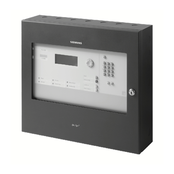
Siemens FC901 Installation Instruction
System installation instruction, wiring diagram, software clearance declaration
Hide thumbs
Also See for FC901:
- System installation instructions (24 pages) ,
- Programming manual (66 pages) ,
- Installation instruction (3 pages)
Summary of Contents for Siemens FC901
- Page 1 FC2005/FC901 System installation instruction Wiring diagram Software clearance declaration FC901 FC2005 Building Technologies Fire Safety & Security Products...
- Page 2 4. Connect the cables to the corresponding position marked on the drawing (The power supply input cable and output cable are not included in the FC901 and FC2005 package). 4. Tie the cables to the enclosure with cable tie, refer to the Figure 1(Cable tie features).
- Page 3 FC2005/FC901 installation instruction Battery, Power supply and City tie PCB assembly installation instruction Pay attention to the battery polarity at 2.1 and 2.2 Detail A 5.2(1) 4.1 and 5.1(1) 5.1(2) Cable tie feature 5.2(2) Power supply DC output Figure 1 Installation instruction(Front view with front door open)
- Page 4 FC2005/FC901 installation instruction City tie cable,Main board and EOL installation instruction From 1 to 4 From left to right: TP1295,TP1294,TP1293,TP1292 TP1295,TP1294,TP1293,TP1292 X2 Output 2 X3 Output 1 Connect to 3.2 Connect to 3.3 Detail B City tie cabling Detail C...
- Page 5 FC2005/FC901 installation instruction Power supply MOV(Metal Oxide Varistor) Installation instruction Step 1: Bend the MOV connector pin refer to the picture for an example Step 2: Fix or weld the MOV onto the power input connector.Take the picture as reference Step 3: Fix the AC input cable and screws on the connector.
- Page 6 FC2005/FC901 installation instruction Installation instruction without Trim kit 5 7/64” 18 1/8” Cerberus Mount Control Unit at a convenient height for access to display and controls Building Technologies Document ID: A5Q00039713A FC2005/FC901 installation instruction Fire Safety & Security Products Page 5/12...
- Page 7 FC2005/FC901 installation instruction Installation instruction with Trim kit 4 1/4” MAX 21 1/4” Cerberus Mount Control Unit at a convenient height for access to display and controls Building Technologies Document ID: A5Q00039713A FC2005/FC901 installation instruction Fire Safety & Security Products Page 6/12 02.2012...
- Page 8 FC2005/FC901 SYSTEM CONNECTION DIAGRAM FC2005/FC901 SYSTEM GENERAL SPECIFICATION Environm ental SLC Addressable Device Circuits Operating temperature - 32 - 120°F (0 - 49°C) 32 VDC Max Relative humidity - Up to 93% @ 90°F (32°C) Pow er limited To be installed in a indoor dry protected environment only Supervised Max.
- Page 9 FC2005/FC901 SYSTEM CONNECTION DIAGRAM FC2005/FC901 SYSTEM CONNECTION DIAGRAM Note: All the wiring must be in according with local codes and National Electric Code. Building Technologies Document ID: A5Q00039713A FC2005/FC901 installation instruction Fire Safety & Security Products Page 8/12 02.2012...
- Page 10 FC2005/FC901 SYSTEM CONNECTION DIAGRAM FC2005/FC901 SYSTEM CONNECTION DIAGRAM SLC loop connections Supervised and power limited, detail device compatibility list refer to user manual Appendix B Class A Class B 50 max devices Auxiliary power Non supervised and power limited Auxiliary power output 2...
- Page 11 FC2005/FC901 SYSTEM CONNECTION DIAGRAM FC2005/FC901 SYSTEM CONNECTION DIAGRAM Series Interface Circuit Power limited City tie or lease line power limited C it y t ie and leased line r at ing Output 1 Output 2 100mA@26VDC Active (19-28VDC on Battery)
- Page 12 FC2005/FC901 SYSTEM CONNECTION DIAGRAM FC2005/FC901 SYSTEM CONNECTION DIAGRAM DACT Power limited DACT compatibility list Device m odule Manufacture MX8000 Honeyw ell (Primary Lines Incoming Telco Phone Lines) (Secondary Lines Incoming Telco Phone Lines) Ring Ring Ring Ring To premises phones...


