Table of Contents
Quick Links
Table of Contents

Related Manuals for Emerson Dixell XC645D


Summary of Contents for Emerson Dixell XC645D
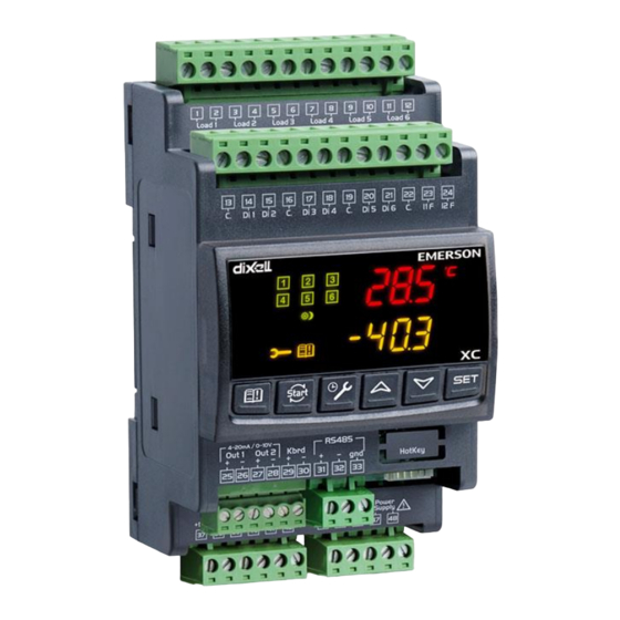
- Page 1 XC645D (v. 3.4)
-
Page 2: Table Of Contents
INDEX BEFORE PROCEEDING XC645D HECK THE SW REL OF THE GENERAL WARNING LEASE READ BEFORE USING THIS MANUAL AFETY RECAUTIONS GENERAL DESCRIPTION COMPONENTS RELATED TO THE XC645D PP07, PP11, PP30 PP50: 4÷20 PRESSURE TRANSDUCERS NP4-67: PIPE MOUNTING TEMPERATURE PROBE WIRING & ELECTRICAL CONNECTIONS ENERAL WARNINGS IRING CONNECTIONS ROBES CONNECTION... - Page 3 12.2 UTPUT DISABLED SIGNALING 12.3 EGULATION WITH SOME OUTPUTS DISABLED RUNNING HOURS OF LOADS 13.1 OW TO DISPLAY THE RUNNING HOURS OF A LOAD 13.2 OW TO RESET THE RUNNING HOURS OF A LOAD ALARM MENU 14.1 OW TO SEE THE ALARMS KEYBOARD LOCKING 15.1 OW TO LOCK THE KEYBOARD...
-
Page 4: Before Proceeding
1. BEFORE PROCEEDING 1.1 Check the sw rel. of the XC645D Look at the SW rel. of XC64D printed on the label of the controller. If the SW release is 3.4, proceed with this manual otherwise contact Dixell to get the right manual. -
Page 5: General Description
3. General description The XC645D is designed to manage both compressors and fans in a condensing system such as a pack. The compressors can be digital scroll or Stream, simple, multistage. Control is by means of a neutral zone and is based on the pressure or temperature sensed in the LP suction (compressors) and HP (condenser) circuits. -
Page 6: Wiring & Electrical Connections
5. WIRING & ELECTRICAL CONNECTIONS 5.1 General warnings Before connecting cables make sure the power supply complies with the instrument’s requirements. Separate the probe cables from the power supply cables, from the outputs and the power connections. Do not exceed the maximum current allowed on each relay 5A resistive, in case of heavier loads use a suitable external relay. -
Page 7: P Robes Connection
5.3 Remote keyboard connection – Only for XC645D -7x0xx- or XC645D -7x2xx- **** ONLY FOR THE MODELS WITH 90-260Vac POWER SUPPLY IDENTIFIED BY THE FOLLOWING PART NUMBERS: XC645D -7x0xx- or XC645D -7x2xx-**** The VC660, remote keyboard for XC600D series, can be connected only to the models with the above part numbers. -
Page 8: Load Connections
5.5 LOAD CONNECTIONS !!!WARNING: Digital Scroll valve coil can operate at main voltage (230Vac or 115Vac) or 24Vac. In case of 24Vac short circuit terminals 1-2. 5.5.1 Connections for models at 230V or 115V and coil of digital valve at 115 or 230V. - Page 9 LOAD TERM. SAFETY TERMINALS SETTING CONNECTION INPUT Load 1 13-14 iF01 = oA1 (digital) Load 2 13-15 iF02 = oA2 Load 3 9-10 16-17 iF03 = oA3 Load 4 11-12 16-18 iF04 = oA4 5.6.2 Additional Configurable digital inputs. The controller XC645D is provided with 3 additional configurable digital inputs, one of them can operate also as probe.
-
Page 10: Mounting & Installation
Terminals Related parameter 25[+] – 26[-]. Analog output 1 AOC: Kind of signal (4-20mA/0-10V) AOF: function 27[+] – 28[-]. Analog output 2 2AOC: Kind of signal (4-20mA/0-10V) 2AOF: function 5.9 How to connect monitoring system - RS485 Serial line The Adr parameter is the number to identify each electronic board. Address duplication is not permitted, in this case the communication with monitoring system is not guaranteed (the Adr is also the ModBUS address). -
Page 11: First Installation
7. First installation At first installation, it’s necessary the following: Select the kind of gas. Set the range of the pressure probes. In the following paragraph a short cut for the above operations. Chapters 11 Parameters programming and 17 will show in detail these operations. 7.1 How to set the kind of gas The kind of gas is set by the parameter FtyP. -
Page 12: User Interface
Select the PA04, adjustment of read out corresponding to 4mA (0.5V), parameter. Press the “SET” key: the value of the parameter will start blinking. Set the lower value of the probe range. Push the SET key to confirm the value. The PA20: adjustment of read out corresponding to 20mA (4.5V) parameter will be displayed. -
Page 13: Icon
In programming mode: it browses the parameter codes or decreases the displayed value. Manual restart of loads: By holding it pressed for 3s, it switches on again loads previous locked by a safety digital input alarm. MAINTEINANCE/CLOCK: To display the loads running hours By holding it pressed for 3s the Maintaining menu is entered To enter the Alarm menu KEY COMBINATIONS... -
Page 14: How To See And Modify The Set Point(S)
9. How to see and modify the set point(s) 9.1 How to see the set point of compressors and/or fans If the controller is managing both compressors and fans, both the set points are displayed in sequence, otherwise only the set point of the enabled section will be displayed. Push and release the SET key;... -
Page 15: Parameters Programming
• LInJ: status of the injection output (“On” – “OFF”), This information is available only if one relay, oA2 ÷oA4 is set as “Lin”. • SEtd: value of the Dynamic Set point. This information is available only if the Dynamic set point function is enabled (par. dSEP ≠... -
Page 16: H Ow To Change Parameter Values
NOTE: each parameter in “Pr2” can be removed or put into “Pr1” (user level) by pressing “SET” + n. When a parameter is present also in “Pr1” decimal point of the lower display is on. 11.3 How to change parameter values 1. -
Page 17: Running Hours Of Loads
13. Running hours of loads 13.1 How to display the running hours of a load. The controller memorizes the running hours of each load. To see how long a load has been working follow this procedure: Press and release the “MAINTENANCE/CLOCK ( )”... -
Page 18: Keyboard Locking
15. Keyboard locking 15.1 How to lock the keyboard Keep the o and n keys pressed together for more than 3 s the o and n keys. The “POF” message will be displayed and the keyboard is locked. At this point it is only possible to view the set point or enter the HACCP menu. - Page 19 oA2 (term. 7-8), oA3 (term. 9-10), oA4 (term. 11-12), outputs 2 3 4 configuration: by means of these parameters the plant can be dimensioned according to the number and type of compressors and/or fans and the number of steps for each one. Each relay according to the configuration of the oA(i), where (i) = 1, 2, 3, 4, parameter can work as: Not used: oA(i) = nu...
- Page 20 Plant with 4 compressors with inverter for fans: oA1 = dGS, oA2 = CPr, oA3 = CPr, oA4 = CPr, dGty = SCrL AOC = tEn AOF = InF dGty Kind of digital compressor SCrL = Digital Scroll: the range of capacity modulation starts from 10% to 100% StrM = Digital Stream: the range of capacity modulation starts from 0% to 100% Valve outputs (unloader) polarity: polarity of the outputs for capacity valves.
-
Page 21: P Robes Configuration
NOTE: The digital scroll compressor is always started as first and switched off as last. In any case, if it is locked because of safety timers, it can be started to maintain the pressure in the regulation band. See par. dGSP Fan rotation enabling YES = rotation enabled: this algorithm distributes the working time between the various fans to ensure even run times. -
Page 22: C Onfigurable Digital Inputs Configuration
3P04: Adjustment of read out for the Probe 3 (used only if P3c=Cur or tEn). corresponding to 4mA or 0.5V input signal, given by the delivery probe (-1.0 ÷ FA20bar; -15÷FA20PSI; -100 ÷ FA20KPA) 3P20: Adjustment of read out for the Probe 3 corresponding to 20mA or 4.5V input signal, given by the condensing probe (PA04 ÷... -
Page 23: D Isplay And M Easurement Unit
NB: THE ABOVE FUNCTIONALITIES ARE ENABLED ONLY WHEN P4C=NP. With P4C = nt10 or nt86 this input is operating as a NTC 10K temperature sensor or NTC 86K temperature sensor iF08 Digital input 8 configuration (terminals 22-24): For the values see iF01; Factory setting iP01 Digital input 1 polarity (13-14): oP: the digital input is activated by opening the contact;... -
Page 24: C Ompressor Regulation
dEU: Selection of the kind of measurement unit: pressure or temperature dEU = tMP: the parameters referred to pressure/temperature will be expressed in temperature according to the value of the CF parameter (°C or °F) dEU = PrS: the parameters referred to pressure/temperature will be expressed in pressure according to the value of the PMU parameter (bar, PSI or KPA) Measurement unit for temperature: it is used only with dEU = tMP, and it set the measurement unit for parameters referred to temperature/pressure. -
Page 25: L Iquid Injection Thermostat
tMin Maximum DGS functioning time at a capacity lower than MinP, before working at full capacity (PMA) (1÷255min) tMAS Time of DGS functioning at maximum capacity (PMA) to restore the right lubrication (1÷255min) Energy saving value for compressors: (-20÷20bar; -50÷50°C) this value is add to the compressor set point. -
Page 26: A Larms – Compressor Section
Time delay between the insertion of two different fans (0÷255sec). Time delay between switching off of two different compressors (0÷255 sec) Minimum set point for fan: The measurement unit depends on dEU parameter. It sets the minimum value that can be used for the set point, to prevent the end user from setting incorrect values. -
Page 27: A Larms – Fans Section
17.10 Alarms – fans section Low pressure alarm – fans section: The measurement unit depends on the dEU LAF: parameter: (FA04 ÷ HAF bar; -50.0÷HAF °C; FA04÷HAF PSI; -58÷HAF °F) It’s independent from the set point. When the value LAF is reached the LA2 alarm is enabled, (possibly after the AFd delay time). -
Page 28: D Ynamic Set Point For Fan
ASH9 Probe selection for superheat monitoring (nP, P3, P4) ASH9 = nP no superheat control ASH9 = P3 the probe to calculate the superheat (SH) is the probe P3 (term. 38-42) ASH9 = P4 the probe to calculate the superheat (SH) is the probe P4 (term. 22-23). In this case also the parameter P4C must be set as nt10 or nt86. -
Page 29: O Ther
17.14 Other Alarm relay silencing: by pushing one of the keypad buttons. no= alarm relay stays on; yES= alarm relay is switched off by pushing any keys. Alarm relay output polarity: cL=closed when activated; oP= opened when activated Switching ON/OFF enabling from keyboard: (no = disabled; yES= enabled) It permits the switching ON/OFF of the instrument by pressing the SET key for more than 4s. - Page 30 18.1.2 Regulation Start: increasing capacity The regulation starts when the suction pressure (temperature) increases and reaches the value SET-Pbd/2+(Pbd*PM)/100. At first, if available, the digital compressor is powered, and it is modulated in PWM mode. NOTE: At start up the valve is energized for SUt seconds. Within the adjustment range (SET–Pbd/2 ÷...
- Page 31 This procedure continues with all active loads, with the shutdowns spaced out by the doF time setting. When only the DGS remains on, at the end of the doF time the DGS is shut down too. 18.1.4 Digital Stream: Main parameters set up EG: Plant with 2 compressors Stream 6D and 2 fans default configuration with PP11, PP30 pressure transducers: oA1 = dGS...
-
Page 32: P Roportional B And Regulation - Only For Fans
18.1.5 Limitation of digital compressor capacity by parameters PM and The capacity of the DGS compressor can be limited by the PM and PMA parameters, as shown in the following diagram. The capacity of the DGS compressor is limited by the PM and PMA parameters, where PM: in percentage, it sets the minimum capacity of the DGS activation during a period tdS. - Page 33 Regulation according to the running hours The algorithm switch on and off the loads according to the running hours of each load. In this way the running hours are balanced. Example 4 Fans: oA2 =FAn; oA3 = FAn; oA4 = FAn; oA6 = FAn: rot = yES rotation enabled ALL LOADS ON Set+Pb/2...
- Page 34 18.3 Condenser with Inverter or Ec Fans–Analog Output Setting This configuration is used when all fans of the condensing group are ECI fans or driven by one inverter or a chopped phase driver. The capacity used by the inverter is proportional to the delivery pressure value inside the regulation band (SETF-Pb/2÷...
- Page 35 18.4.1 Analog output “free” configurations and Parameters Parameter Description Action AoC = tEn Analog output setting Set the output as 0-10V AoF = FrE Analog output function Set the output to drive for instance a de- superheater It’s possible to set only P3 or P4 probes. AOP = P3 Reference probe...
- Page 36 19. Additional functions 19.1 Compressor running proof function The digital inputs are normally used to signal a compressor or fan failure It’s also possible to set the digital inputs for running proof signalling. That means when compressor relay is activated, after a configurable delay the digital input related to the compressor should goes on too (usually a contact from compressor contactor) and the controller has the “confirmation”...
- Page 37 19.2 Flood protection function To ensure the maximum safety of the plant, a relay is activated when the compressors can’t be switched on since they are blocked due to safety times or for other issues or stopped for maintenance. This output can be used to block the liquid injection to the cabinets to avoid to flood the suction collectors.
- Page 38 19.3.1 Suction Superheat detecting To detect the suction superheat an auxiliary probe among P3 (term. 38-42) or P4 (term. 22- 23) has to be set as superheat temperature probe. To do this set ASH9 = P3 or P4. Controller automatically calculates the suction superheat using...
-
Page 39: Alarm List
ASH7 < Superheat < ASH7 – ASH8 Status. Dove SH = valore di SH 19.4.3 Special conditions With ASH9 = nP: none probe set as SH probe and one relays set as HGi (valve for hot gas injection) the configuration error is displayed “no Probe For SH”, and the relay set as HGi is never activated.. - Page 40 Mess. Errata Corrige • StEP ConFiG Load (step) configuration A relay oA(i) has been set as Error error compressor without a previous relay oA(i-1) has been set as compressor. EI oA1 = StP • no P3 ProbE The P3 probe is Check the parameters P3C PrESEnt requested for a function,...
- Page 41 Electronic low pressure: every time the suction temperature/pressure is less than ELP value all the compressors are switched off. The instrument restarts the standard operating mode when pressure/ temperature increases. 20.1.3 E0H1, E0L1 Pressure switch alarm, suction and condensing sections Terminals WARNING: THESE TERMINALS REQUIRE A MAIN OF VOLTAGE CONNECTION Low pressure switch input: 44-45, high pressure switch input:...
-
Page 42: B Uzzer Muting
Recovery Automatic as soon as probe restarts working. 20.1.6 C1HA, C1LA, F-HA, F-LA High and low pressure (temperature) alarms for compressors or fans This alarm signals that the pressure (temperature) is out of limits established by parameters LAL and HAL for compressors and LAF –HAF for fans. The tAo and AFd parameters set the delay between alarm condition and alarm signaling. - Page 43 Code Description Cause Action Reset P1 probe Probe failure or Automatically as soon as the probe restarts working. failure alarm out of range compressors are activated according to the SPr or PoPr parameters. P2 probe Probe failure or Automatically as soon as the probe restarts working.
- Page 44 Code Description Cause Action Reset Liquid level Input enabled signaling only Automatically as soon as the input is disabled alarm Configuratio See par. 18.1 n alarms Load A load has - signaling only Manually: reset the running hour of the compressor maintenance worked for the (see par.0...
-
Page 45: Technical Features
21. Technical features Housing: Self extinguishing ABS. Case: 4 DIN modules 70x135mm with male and female connectors; depth 60mm. Mounting: DIN RAIL mounted in an omega (3) din rail. Protection: IP20. Connections: pluggable screw terminal block 2.5 mm wiring. Power supply: 230Vac ±10%. - Page 46 Value Menù Description Range Label Load 3 configuration nu - CPr1 - CPr2 - StP - dGS - 6dG - dGSt - InC1 - InC2 - FAn - InF - LIn – ALr – Liq - HGi Load 4 configuration nu - CPr1 - CPr2 - StP - dGS - 6dG - dGSt - InC1 - InC2 - FAn - InF - LIn –...
- Page 47 Value Menù Description Range Label Configurable digital input 5 function nu - OA1- OA2 - OA3 - OA4 - OA5 - OA6 - (terminals 19-20) InF - LP1 - LP2 - HP - ES - OFF - LL - SIL – iF05 EAL –...
- Page 48 Value Menù Description Range Label Max time at MinP to start the safety 1÷255min tMin lubrication function Time at PMA for digital compressor to restore 1÷255min tMAS the right lubrication Energy saving for compressors regulation -50.0÷50.0(°C) -90÷90(°F) - 20.0÷20.0(BAR) -300÷300(PSI) - 2000÷2000(KPA) Minimum delay between 2 switching on of the 0 ÷...
- Page 49 Value Menù Description Range Label DLT high temperature alarm threshold 0÷180°C 32÷356°F 110.0 DLT high temperature alarm delay 0÷15min DLT high temperature alarm differential for 0.1÷25.5°C 1÷50°F 15.0 recovery Probe selection for DLT control nP - P3 - P4 dtLi Digital Compressor Capacity percentage in 0÷80(%) dtLP...
- Page 50 Value Menù Description Range Label Maximum analog output percentage when 0 ÷ 100 (%) silence mode function is enabled Alarm relay silencing no – yES Polarity alarm relay OP – CL off function enabled no – yES Buzzer enabled no – yES Serial address 1 ÷...