Quick Links
Digital controller with cooling or heating action
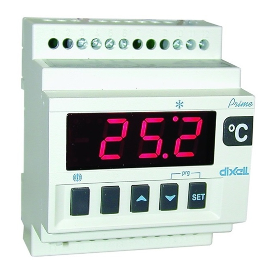
XR10C – XR10D
1. GENERAL WARNING
1.1 PLEASE READ BEFORE USING THIS MANUAL
This manual is part of the product and should be kept near the instrument for
easy and quick reference.
The instrument shall not be used for purposes different from those described
hereunder. It cannot be used as a safety device.
Check the application limits before proceeding.
Dixell Srl reserves the right to change the composition of its products, even
without notice, ensuring the same and unchanged functionality.
1.2
SAFETY PRECAUTIONS
Check the supply voltage is correct before connecting the instrument.
Do not expose to water or moisture: use the controller only within the
operating limits avoiding sudden temperature changes with high atmospheric
humidity to prevent formation of condensation
Warning:
disconnect
all electrical connections before any kind of
maintenance.
Fit the probe where it is not accessible by the End User. The instrument must
not be opened.
In case of failure or faulty operation send the instrument back to the
distributor or to "Dixell S.r.l." (see address) with a detailed description of the
fault.
Consider the maximum current which can be applied to each relay (see
Technical Data).
Ensure that the wires for probes, loads and the power supply are separated
and far enough from each other, without crossing or intertwining.
In case of applications in industrial environments, the use of mains filters (our
mod. FT1) in parallel with inductive loads could be useful.
2. GENERAL DESCRIPTION
Models XR10C, format 32 x 74 mm, and XR10D, DIN rail format, are a single
stage temperature controllers suitable for applications in the field of refrigeration
or heating.
It provides a relay output and a PTC or NTC probe input. The
instrument is fully configurable through special parameters that can be easily
programmed through the keyboard.
3. CONTROLLING LOADS
3.1 THE REGULATION OUTPUT
The regulation is performed according to the temperature measured by the probe.
The instruments are provided with the CH programmable parameter which
enables the user to set the regulation both for heating or cooling applications:
·
CH = CL: cooling applications
·
CH = Ht: heating applications
3.2 CH = CL: COOLING APPLICATIONS.
The Hy value is automatically set above the Set Point. If the temperature
increases and reaches set point plus differential the compressor is started and
then turned off when the temperature reaches the set point value again.
3.3 CH = HT: HEATING APPLICATION.
The Hy value is automatically set under the Set Point. If the temperature
decreases and reaches set point minus differential the regulation output is
activated and then turned off when the temperature reaches the set point value
again.
1592007201 XR10C-D GB r1.0 18.11.2015
4. FRONT PANEL COMMANDS
SET: To display target set point; in programming mode it selects a parameter or
confirm an operation.
o (UP): To see the last temperature alarm happened; in programming mode it
browses the parameter codes or increases the displayed value.
n (DOWN) To see the last temperature alarm happened; in programming mode it
browses the parameter codes or decreases the displayed value.
KEY COMBINATIONS:
o + n To lock & unlock the keyboard.
SET + n To enter in programming mode.
SET + o To return to the room temperature display.
4.1 USE OF LEDS
Each LED function is described in the following table.
LED
MODE
ON
Output enabled
Flashin
-Programming Phase (flashing with LED1)
g
- Anti-short cycle delay enabled
LED1 Flashin
- Programming Phase (flashing with
g
ON
An temperature alarm happened
5. TEMPERATURE ALARM AND ITS DURATION
RECORDING (HACCP)
XR10C signals and records temperature alarms, together with their duration and
max value reached. See drawing:
Ex. High temperature alarm
Temperature
Max
Temperature
ALu
High temp. alarm
ALL
Low temp. alarm
5.1 HOW TO SEE THE ALARM DURATION AND MAX (MIN)
TEMPERATURE
If the alarm LED is on, an alarm has taken place.
To see the kind of alarm, the max (min) reached temperature and alarm duration
do as follows:
1.
Push the Up or Down key.
2.
On the display the following message is shown::
"HAL" for high temperature alarm ("LAL" fot the minimum allarm), followed
by the Maximum (minimum) temperature.
Then the "tiM" (tiMe) message is displayed, followed by the "Duration" in
h.mm.
3.
Then the instrument displays the temperature once again.
NOTE1: if an alarm is still occurring the "tim" shows the partial duration.
NOTE2: the alarm is recorded when the temperature come back to normal values
5.2 HOW TO RESET A RECORDED ALARM OR ONE THAT IS
STILL OCCURRING
1.
Hold the SET key pressed for more than 3s, while the recorded alarm is
displayed. (the rSt message will be displayed)
To confirm the operation, the "rSt" message starts blinking and the normal
2.
temperature will be displayed.
XR10C – XR10D
XR10C
LED1
XR10D
LED1
FUNCTION
)
X
X
Safe food zone
Set
Alarm duration
X
Time
1/4

Related Manuals for Emerson Dixell XR10C


Summary of Contents for Emerson Dixell XR10C
- Page 1 4. FRONT PANEL COMMANDS Digital controller with cooling or heating action XR10C XR10C – XR10D LED1 1. GENERAL WARNING 1.1 PLEASE READ BEFORE USING THIS MANUAL This manual is part of the product and should be kept near the instrument for easy and quick reference.
- Page 2 6. MAIN FUNCTIONS COF Compressor OFF time with faulty probe: (0÷255 min) time during which the compressor is OFF in case of faulty thermostat probe. With COF=0 compressor is always active. 6.1 HOW TO SEE THE SETPOINT CH Type of action: CL = cooling; Ht = heating. Push and immediately release the SET key: the display will DISPLAY show the Set point value;...
- Page 3 8.6 DIGITAL INPUTS POLARITY 12.1 ALARM RECOVERY The digital input polarity depends on the “i1P” parameter. Probe alarm “P1” starts some seconds after the fault in the related probe; it i1P=CL: the input is activated by closing the contact. automatically stops some seconds after the probe restarts normal operation. Check connections before replacing the probe.
- Page 4 14.3 XR10D: 8A COMPRESSOR Power Supply 11 12 8(3)A/250Vac 13 14 15 16 17 18 19 n.c. Comp Line 24Vac/dc supply: connect to the terminals 11 and 12. 120Vac supply: connect to the terminals 11 and 12. 230Vac supply: connect to the terminals 11 and 12. 14.4 XR10D: 20A COMPRESSOR Power Supply...