Allen-Bradley 140G-R Installation Instructions Manual
Hide thumbs
Also See for 140G-R:
- Installation manual (6 pages) ,
- Manual (6 pages) ,
- Installation instructions (4 pages)
Table of Contents
DIR 1000682R0002 Version 03 140G-R_
Installation instruction for 140G-R
Istruzioni di installazione
Installationsanleitung
Instructions pour l'installation
Instrucciones de instalación
Installation - Installazione - Instalación
Instalação -
WARNING:
To prevent electrical shock, disconnect from power source before
installing or servicing. Install in suitable enclosure. Keep free from contaminants.
(Follow NFPA70E requirements).
AVVERTENZA:
Per prevenire infortuni, togliere tensione prima dell'installazione o
manutenzione. Installare in custodia idonea. Tenere lontano da contaminanti.
WARNUNG:
Vor Installations- oder Servicearbeiten Stromversorgung zur
Vermeidung von elektrischen Unfällen trennen. Die Geräte müssen in einem
passenden Gehäuse eingebaut und gegen Verschmutzung geschützt werden.
AVERTISSEMENT:
Avant le montage et la mise en service, couper l'alimentation
secteur pour éviter toute décharge. Prévoir une mise en coffret ou armoire appropriée.
Protéger le produit contre les environnements agressifs.
ADVERTENCIA:
Desconéctese de la corriente eléctrica, antes de la instalación o
del servicio, a fin de impedir sacudidas eléctricas. Instálelo en una caja apropiada.
Manténgalo libre de contaminantes.
ATENÇÃO: Para evitar choques, desconectar da corrente elétrica antes de fazer a
instalação ou a manutenção. Instalar em caixa apropriada. Manter livre de
contaminantes.
2500A (100%)
3p
3000A
2500A (100%)
4p
3000A
NOTE: MCCB without door interlock is not shown
DIR 1000682R0002 Version 03
-
T25
A
SCREW M5 x 14
NUT M5
A - PLAIN WASHER
B - ELASTIC WASHER
2000A
2500A (80%)
X1
2000A
2500A (80%)
X1
(1)
3000A ONLY
Ch10
B
CH19
X2
X3
X48
X3
X2
X64
Bul. 140G
Required tool
xx lb-in
xx Nm
3000A 100%
3000A 100%
3000A ONLY
ONLY
ONLY
SCREW M4 x 14
X24
X8
X32
X32
X10
X40
Escutcheon
X1
X1
Table of Contents

Related Manuals for Allen-Bradley 140G-R


Summary of Contents for Allen-Bradley 140G-R
- Page 1 Bul. 140G DIR 1000682R0002 Version 03 140G-R_ Installation instruction for 140G-R Istruzioni di installazione Installationsanleitung Instructions pour l’installation Instrucciones de instalación Installation - Installazione - Instalación Instalação - Required tool WARNING: To prevent electrical shock, disconnect from power source before installing or servicing.
-
Page 2: Table Of Contents
Index Important User Information ............ 3 Maintenance ............13 Warnings ................13 Description ..............4 Maintenance program ............13 General characteristics ............4 8.2.1 Circuit breaker life .............. 13 External front view of the circuit breaker ......4 8.2.2 Maintenance program ............13 First Level maintenance operations ........ -
Page 3: Important User Information
Important User Information Read this document and the documents listed in the additional resources section about installation, confi guration, and operation of this equipment before you install, confi gure, operate, or mantain this product. Users are required to familiariza themselves with installation and wiring instructions in addition to requirements of all applicable codes, laws, and standards. -
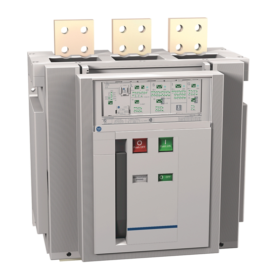
Page 4: Description
General characteristics 140G-R MCCB and molded case switch consist of a plastic structure which houses the operating mechanism, the poles and the auxiliary parts. Each pole is insulated from the others and contains circuit breaking parts and the current sensor of the corresponding phase. -
Page 5: Installation
Comply with the following instructions when lifting the circuit breaker: the circuit breakers must be placed on a sturdy surface and preferably lifted with an appropriate fork-lift truck. The use of ropes is permitted: In this case, the lifting ropes must be attached as shown in the fi gure 6. Fig. -
Page 6: Installation Of The Escutcheon For Fl Ush Mounted (To Door) Applications
Installation of the escutcheon for fl ush mounted (to door) applications - Drill the holes in the enclosure door indicated in the section entitled “Overall dimensions”. - Install the escutcheon (Fig. 8) to the front of the enclosure door. Attach from the inside using self tapping screws (2). Fig. -
Page 7: Mechanical Door Interlock Operating Instruction (Factory Supplied Option)
Mechanical Door Interlock operating instruction (factory supplied option) 4.5.1 Normal operating conditions (interlock armed) • Panel door can be opened with circuit-breaker open only • If panel door is open it is not possible to close the circuit-breaker OPEN APERTO AUS-STELLUNG OUVERT ABIERTO... -
Page 8: Electrical Connections
Examples of connection busbar layouts depending on the types of terminals The busbars allow connections to be made between the terminals of the MCCB and the system bus The following table illustrates the minimum dimensional cross section for busbar connection. Busbar Dimensions Terminal Torque 140G-R Qty. Wrench Terminal Hole... -
Page 9: Assembly Procedures For The Busbar Connection
There are variables when using different dimensional sized busbar, and/or the number of busbars. It is requirement to maintain the minimum cross section as shown in the table and use the entire contact surface of the terminal. Vertical busbar for 2500A (100%) and 3000A (80...100%) are required to have .25 inch (6.4 mm) thickness for the inner (3) busbars. -
Page 10: Commissioning The Mccb
Commissioning the MCCB General procedures – Make sure that the power connections to the circuit breaker terminals are tight – Make adjustments to the trip unit protection functions [LSIG]. – Make sure that voltage of the auxiliary circuits is between 85% and 110% of the rated voltage –... -
Page 11: Instructions For Use
Fig.14 Note A transparent plastic cover with IP54 (Purchase separately) can be fl ush mounted to the enclosure door. The cover is equipped with a key lock. 140G-R-BC12 Fig. 15 Circuit breaker closing and opening procedures Circuit breaker operation can be either manual or electrical. - Page 12 c) Circuit breaker closing This operation can only be carried out when the closing springs are fully loaded. Press the push-button (5, Fig. 17) marked with the letter “I” for closing in the manual mode. When there is a shunt closing release, the operation can also be carried out in the remote mode by means of a separate control circuit.
-
Page 13: Maintenance
Maintenance program 8.2.1 Circuit breaker life When regular maintenance is performed, 140G-R circuit breakers - with or without shunt opening or shunt closing devices - can withstand the following operating cycles without replacement of parts. Mechanical life Electrical life Frame rated current [A] N°... -
Page 14: First Level Maintenance Operations
First Level maintenance operations 8.3.1 Preliminary operations: - open the circuit breaker and make sure that the springs of the operating mechanism are discharged. WARNING: disconnect the power circuit and auxiliary circuits and ground the terminals in a visible way on both the supply side and load side. -
Page 15: Mechanical Operating Mechanism
Phase ALARM AND WARNING leds Display On and fi xed The words "ALLEN-BRADLEY" and message with the name of "LSIG-MM" Flashing backlighting (only if 24V DC supply is present) Normal operation Contrast from 100% (display dark) to 0% (display light), after which the words and logo reapper The test result and assessment are at the user's discretion. -
Page 16: Mm Test
8.3.7.4 MM test The test menu is available with the MM trip unit version. 2 possible option can be selected: - Auto Test causes contacts 95s/98s to close for 1s. - Input allows the state of inputs K14/K15 to be verifi ed: On for 15 VDC voltage values, Off for < 2 VDC voltage values. The verifi... -
Page 17: Second Level Maintenance Operations
Second Level maintenance operations 8.4.1 Warnings: WARNING RISK OF ELECTRICAL SHOCK IMPORTANT NOTE: before performing any maintenance operation: - Turn circuit breaker to the OFF position. Make sure springs of the operating mechanism are discharged. - Remove power from Power and Control terminals and visibly ground line side and load side terminals. Rockwell Automation declines any responsibility for the injury of people or property damage resulting from the failure to comply with the instructions set out in this document. -
Page 18: Mechanical Operating Mechanism
- If the undervoltage release is installed, disassemble the coil support and unload the springs of the operating mechanism by closing and opening the circuit breaker. Fig. 27 8.4.5 Mechanical operating mechanism - Clean (use a cleaning product such as Henkel’s 273471 or equivalent if there is a heavy coating of dirt) and lubricate (in the points indicated in fi... -
Page 19: Electrical And Mechanical Accessories
Phase ALARM AND WARNING leds Display On and fi xed The words "ALLEN-BRADLEY" and message with the name of "LSIG-MM" Flashing backlighting (only if 24V DC supply is present) Normal operation Contrast from 100% (display dark) to 0% (display light), after which the words and logo reapper The test result and assessment are at the user's discretion. -
Page 20: Maintenance Operations; Fi Nal Inspections
8.4.8 Maintenance operations; fi nal inspections - Fit all the parts back in place and re-connect the auxiliary power supply if necessary. - Re-assemble the circuit-breaker cover and side guards as shown in fi gure 30. 9.7 lb-in 1.1 Nm Fig. -
Page 21: Troubleshooting Table
Troubleshooting Table The circuit breaker fails to open when the opening pushbutton is pressed The circuit breaker fails to open because opening coil has tripped The circuit breaker fails to open. Tripped on Undervoltage Release. The circuit breaker fails to open when the protection relay release test is performed The circuit breaker fails to close when the closing pushbutton is pressed The circuit breaker fails to close because closing coil has tripped The closing springs cannot be loaded with the manual loading lever... -
Page 22: Accessories
10 Accessories 10.1 Electrical accessories Shunt Trip / Shunt Close (SNT/SNC) A shunt Trip Relay is typically used to remote (electrically) open the circuit-breaker. Used in conjunction with a spring charging motor and the Shunt Close Relay the circuit-breaker can be operated with remote control. This release provides an instantaneous service (*), but can be supplied permanently (**). -
Page 23: Mechanical Locks
Spring Charging Motor for automatic loading of the closing springs (M) Automatically loads the closing springs of the circuit breaker's operating mechanism. Once the circuit breaker has closed, the spring charging motor immediately begins to reload the closing springs. The closing springs can still be charged in the manual mode (using the lever operating mechanism) in a power failure or during maintenance work. 24-30 V AC/DC DC = 500 W Operating voltage... -
Page 24: Trip Unit References
The 140G-R circuit breaker is supplied with a LSIG-MM Trip Unit. Details about the operation of the trip unit are given in the following documents: 140G-IN067 Operating instructions for the protection releases of 140G-N, 140G-NS and 140G-R circuit breakers 140G-IN068 LSIG Getting started 11.1 Safety notes... -
Page 25: Overall Dimensions
12 Overall dimensions Version with front terminals 2000A (80% and 100% rated)/2500A (80% rated) 10.63" 10.63" 10.23" 1 Panel door internal plane reference 2 Drilled M8 holes to mount circuit-breaker (use M8 screws) Refer to fi gure 38 for door interlock hook mounting dimensions. Fig. - Page 26 Version with extended front spreader terminals 2000A/2500A - (IEC only) 10.63" 10.63" 10.23" 1 Panel door internal plane reference 2 Drilled M8 holes for fi xing circuit- breaker (use M8 screws) Refer to fi gure 38 for door interlock hook mounting dimensions. Fig.
- Page 27 Version with (optional 140G-R-TLV3,-TLV4) adjustable rear terminals 2000A (80% and 100% rated) 2500A (80% rated) Horizontal Vertical IEC Only UL/IEC 10.63" 10.63" 10.23" 1 Panel door internal plane reference 2 Drilled M8 holes for fi xing circuit- breaker (use M8 screws) Refer to fi...
- Page 28 Version with vertical rear terminals 2500A (100% rated)/3000A (80% rated) 10.63" 10.63" 1 Panel door internal plane reference 2 Drilled M8 holes for fi xing circuit- breaker (use M8 screws) Refer to fi gure 38 for door interlock hook mounting dimensions. Fig.
- Page 29 Version with vertical rear terminals 3000A (100% rated) 10.63" 10.63" 21.81" 8.27" 25.4 0.79" 16.85" 13.39" 8.43" 1" 9.09" 10.23" 16.14" 21.1" 284.5 11.2" 15.08" 13.03" 8.07" 4.72" 4.72" 5.2" 4.72" 4.72" 43.1 0.24" 3.74" 43.1 1.69" 0.25" 3.74" 0.25" 0.24"...
- Page 30 Version with Lugs for CuAl cables 2000A (100% rated) 2500A (80% rated) 10.63" 136.5 5.4" 110.74 4.4" 6.3" 50Nm 9.5" 136.5 136.5 5.4" 5.4" 16.14" 16.85" 35.8 35.8 1.4 " 1.4 " 10.71" 383.42 15.1" 16.14 " Ø 0.35 " 1 Panel door internal plane reference 2 Drilled M8 holes for fi...
- Page 31 Enclosure min dimensions Holes drilled in enclosure door and door interlock hook (80% rated - 100% rated) Depth 3 POLES 4 POLES 3 Inside edge of enclosure door 4 Enclosure door 5 No. 2 holes for door interlock (use M5 screws) Fig.
-
Page 32: Circuit Diagrams
13 Circuit diagrams WARNING: Carefully read note F on the circuit diagrams before installing the circuit-breaker. OPERATING STATE SHOWN The diagram illustrates the components in the following conditions: - circuit-breaker open - circuits de-energized - releases not tripped - motor operator with unloaded springs. VERSIONS Version without overcurrent release The applications indicated in fi... - Page 33 Circuit diagram symbols (Standards IEC 60617 and CEI 3-14...3-26) Shield (may be drawn in any Terminal or clamp Change-over position con- shape) tact with momentary circuit breaking (limit contact) Time delay Socket and plug Power isolator with auto- matic opening action (female and male) Mechanical or electrical Motor...
- Page 34 Circuit diagram - Operating state EL SNT Three-pole circuit-breaker with LSIG-MM electronic release EL SNT Four-pole circuit-breaker with LSIG-MM electronic release Three-pole or four-pole switch disconnector (34) DIR 1000682R0002 Version 03...
- Page 35 Motor operator, opening, closing and undervoltage releases Uaux. XR11 XR11 XR11 OUT MM LSIG-MM OUT MM - Future Option - INTERNAL ONLY MM IN Signalling contacts Auxiliary circuits of releases LSIG-MM (35) DIR 1000682R0002 Version 03...
- Page 36 Allen-Bradley, Rockwell Software, and Rockwell Automation are trademarks of Rockwell Automation, Inc. Trademarks not belonging to Rockwell Automation are property of their respective companies. Rockwell Automation maintains current product environmental compliance information on its website at http://www.rockwellautomation.com/rockwellautomation/about-us/ sustainability-ethics/product-environmental-compliance.page DIR 1000682R002 Version 03 (B5757) - B1553 Copyright ©...