L404 and L604 Pressuretrol
line voltage pressure controllers that provide oper-
ating control, automatic limit protection, or manual
reset limit protection for pressure systems of up to
2
300 psi (21.1 kg/cm
or 2068 kpa).
Can be used with steam, air, non-combustible gases,
or fluids non-corrosive to the pressure sensing ele-
ment.
Stainless steel diaphragm (except 300 psi [21.1 kg/
2
cm
(2068 kPa)] models) also allows use with am-
monia, oxygen, distilled water, and similar media.
L404B is recommended for supervision of atomiz-
ing medium pressure in oil burner systems.
Models are available with spst, spdt, or dpst switch-
ing and in variety of operating ranges.
Dustproof, trouble-free mercury switches (all mod-
els except L404F, which has snap-acting switch).
Automatic reset models have adjustable, subtractive
differential (except L604M).
Trip-free mechanism on manual reset models as-
sures that limit function of controller cannot be
defeated by jamming reset lever.
L. Z. • Rev. 3-95 • ©Honeywell Inc. 1995
L404A-D,F; L604A,L,M
Pressuretrol
®
Controllers are
®
Controllers
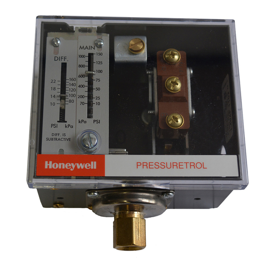
Screw adjustments made on top of case.
Scaleplates marked in English (psi) and Metric
2
(kg/cm
) units.
L404F models available with European enclosure,
British Standard Pipe Threads, ground screw, and
scaleplates marked in kg/cm
Clear plastic cover on case to observe pressure set-
tings and switch action.
Leveling indicator visible through cover.
Hexagonal fitting with 1/4-18 NPT internal threads
for direct mounting to 14026 Steam Trap (siphon
loop).
Surface mount is available using screws through
holes (knockouts) in case backing.
CONTENTS
Specifications ................................................ 2
Ordering Information .................................... 2
Installation .................................................... 5
Setting and Checkout ..................................... 8
Service Information ..................................... 10
2
and either psi or kPa.
60-2150-10

Related Manuals for Honeywell Pressuretrol L404 Series


Summary of Contents for Honeywell Pressuretrol L404 Series
-
Page 1: Table Of Contents
CONTENTS Specifications ..........2 Ordering Information ........2 Installation ............ 5 Setting and Checkout ........8 Service Information ........10 L. Z. • Rev. 3-95 • ©Honeywell Inc. 1995 60-2150-10... -
Page 2: Specifications
Honeywell, 1885 Douglas Drive North Minneapolis, Minnesota 55422-4386 In Canada—Honeywell Limited/Honeywell Limitée, 35 Dynamic Drive, Scarborough, Ontario M1V 4Z9. International Sales and Service Offices in all principal cities of the world. Manufacturing in Australia, Canada, Finland, France, Germany, Japan, Mexico, Netherlands, Spain, Taiwan, United Kingdom, U.S.A. - Page 3 L404A-D,F; L604A,L,M SPECIFICATIONS TABLE 1—MODELS AVAILABLE. Switching Midscale Subtractive Differential Maximum Surge Action on Operating Ranges (Adjustable) Pressure Pressure Rise to Setpoint Model kg/cm kg/cm kg/cm L404A spst, breaks 2 to 15 .14 to 1.0 14 to 103 2 to 6 .14 to .41 14 to 4 circuit...
- Page 4 L404A-D,F; L604A,L,M SPECIFICATIONS DIMENSIONS: See Fig. 1. See Fig. 2 for mounting steam REPLACEMENT PARTS: trap (siphon loop). 129178 Thermoplastic Cover. WEIGHT: 2 IBC. (0.91 kg). 14026 Steam Trap (siphon loop)—1/4 in. black iron pipe. FINISH: Gray. Necessary for boiler installations. APPROVALS: ACCESSORIES: Underwriters Laboratories Inc.
-
Page 5: Installation
L404A-D,F; L604A,L,M INSTALLATION Installation WHEN INSTALLING THIS PRODUCT. . . 1. Read these instructions carefully. Failure to follow Fig. 2—Right and wrong mounting of a steam trap (siphon loop), with approximate dimen- them could damage the product or cause a hazardous sions in in. - Page 6 L404A-D,F; L604A,L,M INSTALLATION Mounting on a Boiler Fig. 3—L404 terminal blocks and internal If it is not convenient to mount the controller alongside schematics. the pressure gauge, install a steam trap (siphon loop) in the fitting provided by the boiler manufacturer. If there is no RISE RISE RISE...
- Page 7 L404A-D,F; L604A,L,M INSTALLATION Fig. 6—L404 with a low voltage relay. Fig. 8—L404F, L604A (with jumper installed) or L604M, used as a low limit, with an alarm circuit. SPDT LOW VOLTAGE RELAY L404 CONTROLLER (HIGH LIMIT) (HOT) POWER 24 VOLT SUPPLY THERMOSTAT FLAME (HOT)
-
Page 8: Setting And Checkout
L404A-D,F; L604A,L,M SETTING AND CHECKOUT Setting and Checkout SETTING main scale setpoint. They will not automatically return to In all models, the differential is subtractive from the their former positions. To reset one of these controllers, main scale set point. The upper operating point is deter- wait until the pressure falls to the set point minus the mined by the main scale set point, while the lower operat- differential (Fig. - Page 9 L404A-D,F; L604A,L,M SETTING AND CHECKOUT CAUTION Boiler Installation If the controller is being used on a boiler installation, test Do not put the system into service until you have it as follows: satisfactorily completed all applicable tests de- 1. Note the boiler pressure by checking the boiler pres- scribed in this Checkout section, in the Checkout sure gauge.
-
Page 10: Service Information
L404A-D,F; L604A,L,M SERVICE INFORMATION Service Information CALIBRATION MAINTENANCE The controller was carefully calibrated during manufac- The cover of the controller should be in place at all times turing and should not require recalibration. Most calibra- to protect the internal components from dirt, dust, and tion errors are caused by improper leveling. - Page 11 60-2150—10...
- Page 12 Home and Building Control Home and Building Control Helping You Control Your World Honeywell Inc. Honeywell Limited—Honeywell Limitée 1985 Douglas Drive North 740 Ellesmere Road Golden Valley, MN 55422 Scarborough, Ontario M1P 2V9 60-2150—10 Printed in U.S.A. www.honeywell.com/bbc...