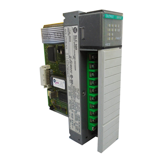
High-Speed Counter Module
(Catalog Numbers 1746-HSCE)
Installation Instructions
Inside..
Important User Information .........................2
For More Information...................................3
Dip Switch and Jumper Locations...............7
Installing the Module .................................10
Removing the Terminal Block....................11
Important Wiring Considerations...............12
Encoders ...................................................14
Specifications ............................................20
page
Table of Contents

Related Manuals for Allen-Bradley 1746-HSCE


Summary of Contents for Allen-Bradley 1746-HSCE
-
Page 1: Table Of Contents
High-Speed Counter Module (Catalog Numbers 1746-HSCE) Installation Instructions page Inside.. Important User Information ......2 For More Information........3 High-Speed Counter Module Overview..4 Dip Switch and Jumper Locations....7 Installing the Module .........10 Removing the Terminal Block....11 Important Wiring Considerations....12 Encoders ...........14 Specifications ..........20... -
Page 2: Important User Information
Since there are many variables and requirements associated with any particular installation, Allen-Bradley does not assume responsibility or liability (to include intellectual property liability) for actual use based upon the examples shown in this publication. -
Page 3: For More Information
For More Information As part of our effort to preserve, protect, and improve our environment, Allen-Bradley is reducing the amount of paper we use. Less paper means more options for you. In addition to traditional printed publications and CD-ROM versions, we now offer on-line manuals with the most up-to-date information you can get. -
Page 4: High-Speed Counter Module Overview
Control of the counter reset is configured through user-set parameters. The counter can be reset from any combination of the Z input, Limit Switch input, or Soft Reset control bits. The 1746-HSCE High-Speed Counter Module is not compatible with the 1747-ASB Remote I/O Adapter Module. Publication 1746-5.16... - Page 5 Module operation is determined by selections made in the Setup and Control Word (M0:e.1). Setting the Function Control bit to 1 triggers the module to start the proper pulse counter, rate measurement, and output control functions. Many parameters are dynamic and can be changed without disrupting counter operation.
- Page 6 Counter Input Rate Period Parameters Parameters Operating Mode Rate Pulse and Output Control Parameters Direction Counter Parameters Operating Input Rate mode Operating Mode Measurement Logic Reset Outputs Logic Parameters Rate Physical Reset Rate Counter Input Outputs Condition Sequencer Pulse Counter Output Status LS Filter Parameters...
-
Page 7: Dip Switch And Jumper Locations
Dip Switch and Jumper Locations Two dip switches (SW1 and SW2) and one jumper (JW1) are located on the side of the module. • SW1 selects the type of input (single ended or differential). • SW2 selects the output voltage range (4.5-10V dc or 10-30V dc). •... - Page 8 SW2 Settings Select an output voltage range that coincides with your supply voltage. The selections are 4.5 - 10V dc or 10 - 30V dc. 1 2 3 4 Switch 10-30V dc Output 1 2 3 4 4.5-10V dc ATTENTION: All switches of SW2 must be ON or all switches must be OFF.
- Page 9 JW1 Settings Select 300 µs or 10 ms filtering to debounce the limit switch input. Position the jumper as follows: 3 2 1 3 2 1 10 ms filter 300 µs filter The LS input allows you to make a direct connection to nominal voltage levels of 5, 12, or 24V dc.
-
Page 10: Installing The Module
Installing the Module Installation procedures for this module are the same as any other discrete I/O or specialty module. Important: Set the dip switches before installing the module. ATTENTION: Disconnect power before attempting to install, remove, or wire the module. Make sure your SLC power supply has adequate reserve current capacity. -
Page 11: Removing The Terminal Block
3. Make sure the removable terminal wiring block is attached to the module and all wires are connected to the terminal block. 4. Insert the cable tie in the slots and secure the cable. 5. Cover all unused slots with the Card Slot Filler, Catalog Number 1746-N2. Removing the Terminal Block The removable terminal wiring block eliminates the need to rewire a module if it is removed from the rack. -
Page 12: Important Wiring Considerations
Important Wiring Considerations Use the following guidelines when planning the system wiring for the module: • Install the SLC 500 system in a NEMA-rated enclosure. • Disconnect power to the SLC processor and the module before wiring. • Make sure the SLC 500 system is properly grounded. •... - Page 13 OUTPUT INPUT FAULT Upper Retaining Screw Maximum HSCE Torque = 0.7-0.9 Nm (6-8 in-lbs) OUT 0 OUT 1 OUT 0 Discrete Output Wiring OUT 2 NOTE: VDC must be externally OUT 1 supplied by the user. See page OUT 3 OUT 2 14 for output wiring.
-
Page 14: Encoders
1500 volts. Encoders The wiring diagrams on the following pages are provided to support the Allen-Bradley encoders you may already have. Differential encoders provide the best immunity to electrical noise. We recommend, whenever possible, to use differential encoders. - Page 15 Differential Encoder Wiring cable + VDC Power Supply Belden 9503 or equivalent 305m (1000ft) max length A(+) A(±) B(+) Allen-Bradley B(±) 845H Series Z(+) differential encoder Z(±) Shield 12 34 encoder connector (all switches ON) housing Earth Module Inputs (1) Refer to your encoder manual for proper cable type and length.
- Page 16 Single-Ended Encoder Wiring (Open Collector) cable + VDC Power Supply Shield A(+) A(±) B(+) Allen-Bradley B(±) 845H Series Z(+) single-ended encoder Z(±) Belden 9503 or equivalent 123 4 305m (1000tft) max length encoder connector (All switches OFF) housing Earth Module Inputs (1) Refer to your encoder manual for proper cable type and length.
- Page 17 +24V dc 4700 ohm 1/4W 5% 1.2 µA (4) The Allen-Bradley 845H sourcing encoder is not compatible with this module. Single-Ended Encoder Output Waveforms The figure below shows the single-ended encoder output waveforms. When the waveform is low, the encoder output transistor is OFF.
- Page 18 Single-Ended Wiring (Discrete Devices) +VDC Power Supply proximity sensor with sourcing output A(+) A(±) solid-state switch B(+) (5V output) B(±) Z(+) Z(±) photoelectric sensor with open collector sinking output 123 4 (All switches OFF) Module Inputs Important: • This diagram shows the sensors operation from a common power supply. Separate power supplies for each circuit can be used.
- Page 19 Limit Switch Wiring (24V dc Hard Contact) ATTENTION: Only connect one LS input range at a time. Otherwise, the module will be damaged. Hard Contact HSCE module Limit Switch LS (24V dc) LS (12V dc) LS (5V dc) 24V dc ±...
-
Page 20: Specifications
Limit Switch Wiring (5V dc Solid State) ATTENTION: Only connect one LS input range at a time. Otherwise, the module will be damaged. Solid State Limit Switch HSCE module LS (24V dc) LS (12V dc) LS (5V dc) 5V dc ±... - Page 21 Inputs A, B, and Z Differential Single Ended (Switch 1 on) (Switch 1 off) ± Input Voltage 5V dc 0 to 5V dc On-State Voltage 2.8 to 4.5V dc 3.1 to 5.5V dc Off-State Voltage -5.5 to 0.8V dc 0 to 0.8V dc Max Off-State Leakage 100 µA 600 µA...
- Page 22 Outputs (Open Collector, Sinking) 4.5 to 10V dc 10 to 30V dc (Switch 2 on) (Switch 2 off) 16 mA at 4.5V dc 40 mA at 10V dc Max. On-State Output Current 40 mA at 10V dc 125 mA at 30V dc Max.
- Page 23 SLC 500 is a trademark of Rockwell Automation. Belden is a trademark of Belden, Inc. Publication Publication 1746-5.16 - June 1999 PN 40071-036-01(B) Supersedes 1746-5.16 - June1998 © 1999 Rockwell International Corporation. All rights reserved. Printed in the U.S.A.