Quick Links
This user's guide describes the characteristics, operation, and use of the LM48580 Evaluation Module
(EVM). A complete schematic diagram, printed-circuit board layouts, and bill of materials (BOM) are
included in this document.
...................................................................................................................
1
2
3
4
5
6
7
8
Bill Of Materials
9
Demonstration Board PCB Layout
1
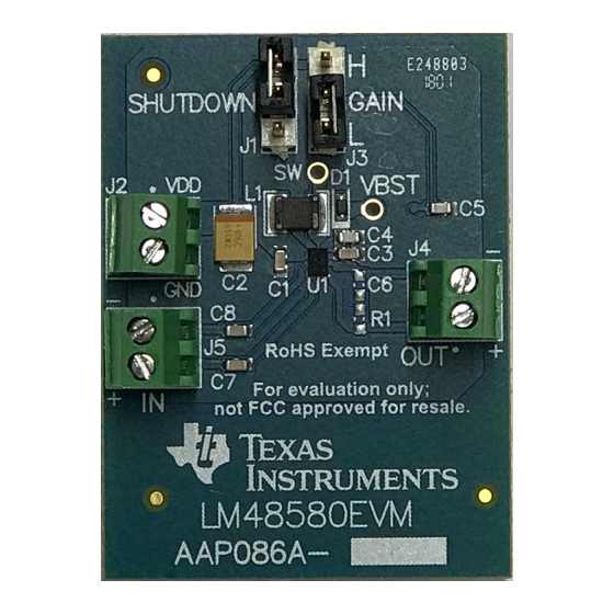
LM48580 Demonstration Board
2
Demonstration Board Schematic
3
Top Overlay
4
Top Solder Mask
.....................................................................................................................
5
Top Layer
6
Bottom Layer
7
Bottom Solder Mask
8
Drill Drawing
1
Operating Conditions
2
Connections
3
LM48580 Bill of Materials
Trademarks
All trademarks are the property of their respective owners.
SNAU231 - February 2018
Submit Documentation Feedback
............................................................................................................
.........................................................................................................
........................................................................................................
..............................................................................................
..................................................................................................................
.....................................................................................................
..............................................................................................................
........................................................................................
............................................................................................
..........................................................................................
..................................................................................................................
.............................................................................................................
.................................................................................................................
.........................................................................................................
..................................................................................................................
........................................................................................................
..................................................................................................................
...................................................................................................
Copyright © 2018, Texas Instruments Incorporated
LM48580 Evaluation Module
Contents
List of Figures
List of Tables
User's Guide
SNAU231 - February 2018
LM48580 Evaluation Module
2
2
3
3
3
4
4
5
6
2
3
6
6
6
6
6
6
3
4
5
1

Related Manuals for Texas Instruments LM48580


Summary of Contents for Texas Instruments LM48580
-
Page 1: Table Of Contents
User's Guide SNAU231 – February 2018 LM48580 Evaluation Module This user's guide describes the characteristics, operation, and use of the LM48580 Evaluation Module (EVM). A complete schematic diagram, printed-circuit board layouts, and bill of materials (BOM) are included in this document. -
Page 2: Introduction
Introduction www.ti.com Introduction To help the user investigate and evaluate the LM48580 performance and capabilities, a fully-populated demonstration board was created. Figure 1 shows the board. Connected to an external power supply (2.5 V ≤ V ≤ 5.5 V) and a signal source, the LM48580 demonstration board easily exercises features of the amplifier. -
Page 3: General Description
The LM48580 features one fully-differential input, a programmable gain pin, and a shutdown pin. The gain pin has three settings for 18 dB, 24 dB, and 30 dB. The LM48580 has a low power shutdown mode that reduces quiescent current consumption to 0.5 μA. -
Page 4: Connections
Minimize trace impedance of the power, ground and all output traces for optimum performance. Voltage loss due to trace resistance between the LM48580 and the load results in decreased output power and efficiency. Trace resistance between the power supply and ground has the same effect as a poorly regulated supply: increased ripple and reduced peak output power. - Page 5 Bill Of Materials www.ti.com Bill Of Materials Table 3 lists the bill of materials for the EVM. Table 3. LM48580 Bill of Materials Package Alternate Part Alternate Designator Quantity Value Description Part Number Manufacturer Reference Number Manufacturer Printed Circuit Board AAP086 –...
- Page 6 Figure 3. Top Overlay Figure 4. Top Solder Mask Figure 5. Top Layer Figure 6. Bottom Layer Figure 7. Bottom Solder Mask Figure 8. Drill Drawing LM48580 Evaluation Module SNAU231 – February 2018 Submit Documentation Feedback Copyright © 2018, Texas Instruments Incorporated...
- Page 7 Revision History NOTE: Page numbers for previous revisions may differ from page numbers in the current version. Date Revision Description February 2018 Initial Release SNAU231 – February 2018 Revision History Submit Documentation Feedback Copyright © 2018, Texas Instruments Incorporated...
- Page 8 IMPORTANT NOTICE FOR TI DESIGN INFORMATION AND RESOURCES Texas Instruments Incorporated (‘TI”) technical, application or other design advice, services or information, including, but not limited to, reference designs and materials relating to evaluation modules, (collectively, “TI Resources”) are intended to assist designers who are developing applications that incorporate TI products;...
- Page 9 Mouser Electronics Authorized Distributor Click to View Pricing, Inventory, Delivery & Lifecycle Information: Texas Instruments LM48580EVM...