Table of Contents
Quick Links
www.ti.com
User's Guide
LMG352XEVM-04X User Guide
The LMG352XEVM-04X features two LMG352XR0X0 650-V GaN FETs with an integrated driver and protection
in a half-bridge configuration with all the required bias circuit and logic/power level shifting. Essential power
stage and gate-driving, high-frequency current loops are fully enclosed on the board to minimize power loop
parasitic inductance for reducing voltage overshoots and improving performance. The LMG352XEVM-04X is
configured for a socket style external connection for easy interface with external power stages to run the
LMG352XR0X0 in various applications. Refer to the LMG352XR0X0 data sheet before using this EVM.
1 General TI High Voltage Evaluation User Safety Guidelines .............................................................................................
1.1 Safety and Precautions......................................................................................................................................................
2
Introduction.............................................................................................................................................................................5
2.1 LMG352XEVM-04X Daughter Card...................................................................................................................................
Boards....................................................................................................................................................................9
Applications............................................................................................................................................................9
2.4 Features.............................................................................................................................................................................
3 LMG352XEVM-04X Schematic.............................................................................................................................................
Schematic......................................................................................................................................................11
5 Recommended Footprint.....................................................................................................................................................
6 Test Equipment.....................................................................................................................................................................
7.1
Setup................................................................................................................................................................................15
7.2 Start-Up and Operating Procedure..................................................................................................................................
Results......................................................................................................................................................................17
Procedure........................................................................................................................................................18
7.5 Additional Operating Notes..............................................................................................................................................
8 Test Procedure When Paired With LMG34XX-BB-EVM.....................................................................................................
8.1
Setup................................................................................................................................................................................19
8.2 Start-Up and Operating Procedure..................................................................................................................................
Procedure........................................................................................................................................................22
8.4 Additional Operation Notes..............................................................................................................................................
9 Bill of Materials.....................................................................................................................................................................
10 Revision History.................................................................................................................................................................
Figure 2-1. LMG352XEVM-04X Block Diagram..........................................................................................................................
Figure 2-2. Front Side View of the EVM......................................................................................................................................
Figure 2-3. Back Side View of the
Figure 2-4. EVM on Coldplate.....................................................................................................................................................
Figure 3-1. LMG352XEVM-04X Schematic...............................................................................................................................
Figure 4-2. LMG34XX-BB-EVM Schematic...............................................................................................................................
Figure 5-1. Recommended Footprint for LMG352XEVM-04X ..................................................................................................
Figure 7-1. LMG342X-BB-EVM Motherboard With LMG352XEVM-04X ..................................................................................
Figure 7-4. Continuous Buck Operation at 4 kW.......................................................................................................................
SNOU178A - OCTOBER 2020 - REVISED FEBRUARY 2021
Submit Document Feedback
ABSTRACT
Table of Contents
LMG342X-BB-EVM......................................................................................................15
List of Figures
EVM.......................................................................................................................................7
Schematic................................................................................................................................11
LMG342X-BB-EVM....................................................................................................16
Conditions.................................................................................................17
LMG34XX-BB-EVM....................................................................................19
Copyright © 2021 Texas Instruments Incorporated
Table of Contents
Connection..........................16
LMG352XEVM-04X User Guide
3
4
5
9
10
13
14
16
18
19
21
22
23
26
6
7
8
10
12
13
15
17
1
Table of Contents

Related Manuals for Texas Instruments LMG352 EVM-04 Series


Summary of Contents for Texas Instruments LMG352 EVM-04 Series
-
Page 1: Table Of Contents
Figure 7-4. Continuous Buck Operation at 4 kW........................Figure 7-5. Fast Slew Rate at 400V/20A Switching Conditions....................17 Figure 8-1. LMG352XEVM-04X Connected to the LMG34XX-BB-EVM..................19 SNOU178A – OCTOBER 2020 – REVISED FEBRUARY 2021 LMG352XEVM-04X User Guide Submit Document Feedback Copyright © 2021 Texas Instruments Incorporated... - Page 2 Table 9-1. Bill of Materials for LMG352XEVM-04X ........................23 Table 9-2. Bill of Materials for LMG342X-BB-EVM........................Trademarks All trademarks are the property of their respective owners. LMG352XEVM-04X User Guide SNOU178A – OCTOBER 2020 – REVISED FEBRUARY 2021 Submit Document Feedback Copyright © 2021 Texas Instruments Incorporated...
-
Page 3: General Ti High Voltage Evaluation User Safety Guidelines
– Wear personal protective equipment like latex gloves and safety glasses with side shields, or protect the EVM from accidental touch in an adequate translucent plastic box with interlocks. • Limitation for Safe Use: SNOU178A – OCTOBER 2020 – REVISED FEBRUARY 2021 LMG352XEVM-04X User Guide Submit Document Feedback Copyright © 2021 Texas Instruments Incorporated... -
Page 4: Safety And Precautions
For safety, use of isolated test equipment with overvoltage and overcurrent protection is highly recommended. LMG352XEVM-04X User Guide SNOU178A – OCTOBER 2020 – REVISED FEBRUARY 2021 Submit Document Feedback Copyright © 2021 Texas Instruments Incorporated... -
Page 5: Introduction
Switch node of the half-bridge configuration Input DC voltage of the half-bridge configuration PGND Power ground of the half-bridge configuration. Functionally isolated from AGND. SNOU178A – OCTOBER 2020 – REVISED FEBRUARY 2021 LMG352XEVM-04X User Guide Submit Document Feedback Copyright © 2021 Texas Instruments Incorporated... -
Page 6: Figure 2-1. Lmg352Xevm-04X Block Diagram
LMG352XEVM-04X User Guide SNOU178A – OCTOBER 2020 – REVISED FEBRUARY 2021 Submit Document Feedback Copyright © 2021 Texas Instruments Incorporated... -
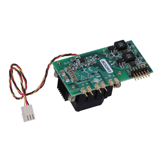
Page 7: Figure 2-2. Front Side View Of The Evm
TIM with sufficient dielectric strength is required. Figure 2-2. Front Side View of the EVM Figure 2-3. Back Side View of the EVM SNOU178A – OCTOBER 2020 – REVISED FEBRUARY 2021 LMG352XEVM-04X User Guide Submit Document Feedback Copyright © 2021 Texas Instruments Incorporated... -
Page 8: Figure 2-4. Evm On Coldplate
SNOAA70 application notes on thermal design. The coldplate used in LMG352XEVM-04X EVM card is custom designed, and please contact TI for more information. Figure 2-4. EVM on Coldplate LMG352XEVM-04X User Guide SNOU178A – OCTOBER 2020 – REVISED FEBRUARY 2021 Submit Document Feedback Copyright © 2021 Texas Instruments Incorporated... -
Page 9: Mother Boards
PWM disables in the event of a fault from the LMG352XEVM-04X • Maximum recommended operating voltage of 520-V and absolute maximum voltage of 650-V SNOU178A – OCTOBER 2020 – REVISED FEBRUARY 2021 LMG352XEVM-04X User Guide Submit Document Feedback Copyright © 2021 Texas Instruments Incorporated... -
Page 10: Lmg352Xevm-04X Schematic
4.7µF PGND SN6505BQDBVTQ1 S2751-46R PGND ISO_RET_L_B PGND AGND PGND HVBUS PGND Power Connector Screw Pin Screw Figure 3-1. LMG352XEVM-04X Schematic LMG352XEVM-04X User Guide SNOU178A – OCTOBER 2020 – REVISED FEBRUARY 2021 Submit Document Feedback Copyright © 2021 Texas Instruments Incorporated... -
Page 11: Mother Board Schematic
0.1uF 0.1uF PGND5 PGND PGND AGND AGND AGND AGND1 PGND4 PGND 3267 PGND1 PGND PGND2 PGND Figure 4-1. LMG342X-BB-EVM Schematic SNOU178A – OCTOBER 2020 – REVISED FEBRUARY 2021 LMG352XEVM-04X User Guide Submit Document Feedback Copyright © 2021 Texas Instruments Incorporated... -
Page 12: Figure 4-2. Lmg34Xx-Bb-Evm Schematic
282834-2 AGND1 AGND PGND PGND Green PGND2 AGND ACMGND AGND2 Copyright © 2016, Texas Instruments Incorporated Figure 4-2. LMG34XX-BB-EVM Schematic LMG352XEVM-04X User Guide SNOU178A – OCTOBER 2020 – REVISED FEBRUARY 2021 Submit Document Feedback Copyright © 2021 Texas Instruments Incorporated... -
Page 13: Recommended Footprint
When the EVM daughter card is used in a custom design system, the recommended footprint to interface with the LMG352XEVM-04X daughter card is shown below. Figure 5-1. Recommended Footprint for LMG352XEVM-04X SNOU178A – OCTOBER 2020 – REVISED FEBRUARY 2021 LMG352XEVM-04X User Guide Submit Document Feedback Copyright © 2021 Texas Instruments Incorporated... -
Page 14: Test Equipment
Fan: For the heatsink-version EVM daughter card, a dedicated cooling fan is attached on the back side of the heatsink. Please make sure the fan is powered by the 12-V power supply before test. LMG352XEVM-04X User Guide SNOU178A – OCTOBER 2020 – REVISED FEBRUARY 2021 Submit Document Feedback Copyright © 2021 Texas Instruments Incorporated... -
Page 15: Test Procedure When Paired With Lmg342X-Bb-Evm
12.Provide 12-V bias supply to fan by connecting the 3-pin power cord from fan to J15. Figure 7-1. LMG342X-BB-EVM Motherboard With LMG352XEVM-04X SNOU178A – OCTOBER 2020 – REVISED FEBRUARY 2021 LMG352XEVM-04X User Guide Submit Document Feedback Copyright © 2021 Texas Instruments Incorporated... -
Page 16: Start-Up And Operating Procedure
(up to 520V). As the voltage is ramping up, the HV LED will turn on and become brighter. Figure 7-3. Switch-Node Voltage Measurement with High-Bandwidth Probe and Pigtail Ground Connection LMG352XEVM-04X User Guide SNOU178A – OCTOBER 2020 – REVISED FEBRUARY 2021 Submit Document Feedback Copyright © 2021 Texas Instruments Incorporated... -
Page 17: Test Results
Figure 7-9. The adjustable slew-rate feature provides the customer a flexibility to adapt the device’s switching speed in different applications. SNOU178A – OCTOBER 2020 – REVISED FEBRUARY 2021 LMG352XEVM-04X User Guide Submit Document Feedback Copyright © 2021 Texas Instruments Incorporated... -
Page 18: Shutdown Procedure
Fault protection on the LMG342X-BB-EVM is not latching, therefore PWM will resume if a fault clears and the LMG342X-BB- EVM is still operational. LMG352XEVM-04X User Guide SNOU178A – OCTOBER 2020 – REVISED FEBRUARY 2021 Submit Document Feedback Copyright © 2021 Texas Instruments Incorporated... -
Page 19: Test Procedure When Paired With Lmg34Xx-Bb-Evm
TI provides a custom interposer board that must be used when the LMG352XEVM-04X is paired with the LMG34XX-BB-EVM. The interposer board is not needed with LMG342x-BB-EVM. Figure 8-1. LMG352XEVM-04X Connected to the LMG34XX-BB-EVM SNOU178A – OCTOBER 2020 – REVISED FEBRUARY 2021 LMG352XEVM-04X User Guide Submit Document Feedback Copyright © 2021 Texas Instruments Incorporated... -
Page 20: Figure 8-2. Recommended Connection Points
4. Connect 12-V bias supply to the fan attached on the EVM, or enable an external fan to direct airflow across the heat sink attached to the LMG352XEVM-04X. LMG352XEVM-04X User Guide SNOU178A – OCTOBER 2020 – REVISED FEBRUARY 2021 Submit Document Feedback Copyright © 2021 Texas Instruments Incorporated... -
Page 21: Start-Up And Operating Procedure
3. Power up the high voltage input supply. Ensure the red “HV Enable” LED is illuminated when the input supply is above 20 V. SNOU178A – OCTOBER 2020 – REVISED FEBRUARY 2021 LMG352XEVM-04X User Guide Submit Document Feedback Copyright © 2021 Texas Instruments Incorporated... -
Page 22: Shutdown Procedure
Fault protection on the LMG34XX-BB-EVM is not latching, therefore PWM will resume if a fault clears and the LMG34XX-BB- EVM is still operational. LMG352XEVM-04X User Guide SNOU178A – OCTOBER 2020 – REVISED FEBRUARY 2021 Submit Document Feedback Copyright © 2021 Texas Instruments Incorporated... -
Page 23: Bill Of Materials
RES, 0, 5%, 0.1 W, AEC-Q200 Grade 0, 0402 ERJ-2GE0R00X R5, R14, R17 RES, 20 k, 5%, 0.1 W, AEC-Q200 Grade 0, 0402 ERJ-2GEJ203X SNOU178A – OCTOBER 2020 – REVISED FEBRUARY 2021 LMG352XEVM-04X User Guide Submit Document Feedback Copyright © 2021 Texas Instruments Incorporated... -
Page 24: Table 9-2. Bill Of Materials For Lmg342X-Bb-Evm
Machine Screw, Round, #4-40 x 1/4, Nylon, Philips panhead NY PMS 440 0025 PH 1902C HS_FET_PWM, LS_FET_PWM, PWM_HS, PWM_LS 4 Test Point, Compact, White, TH 5007 LMG352XEVM-04X User Guide SNOU178A – OCTOBER 2020 – REVISED FEBRUARY 2021 Submit Document Feedback Copyright © 2021 Texas Instruments Incorporated... - Page 25 1A SIMPLE SWITCHER® Power Module with 20V Maximum LMZ12001EXTTZ/NOPB Input Voltage for Military and Rugged Applications, 7 pin TO- PMOD SNOU178A – OCTOBER 2020 – REVISED FEBRUARY 2021 LMG352XEVM-04X User Guide Submit Document Feedback Copyright © 2021 Texas Instruments Incorporated...
-
Page 26: Revision History
NOTE: Page numbers for previous revisions may differ from page numbers in the current version. DATE REVISION NOTES February 2021 Initial Public Release LMG352XEVM-04X User Guide SNOU178A – OCTOBER 2020 – REVISED FEBRUARY 2021 Submit Document Feedback Copyright © 2021 Texas Instruments Incorporated... - Page 27 STANDARD TERMS FOR EVALUATION MODULES Delivery: TI delivers TI evaluation boards, kits, or modules, including any accompanying demonstration software, components, and/or documentation which may be provided together or separately (collectively, an “EVM” or “EVMs”) to the User (“User”) in accordance with the terms set forth herein.
- Page 28 www.ti.com Regulatory Notices: 3.1 United States 3.1.1 Notice applicable to EVMs not FCC-Approved: FCC NOTICE: This kit is designed to allow product developers to evaluate electronic components, circuitry, or software associated with the kit to determine whether to incorporate such items in a finished product and software developers to write software applications for use with the end product.
- Page 29 www.ti.com Concernant les EVMs avec antennes détachables Conformément à la réglementation d'Industrie Canada, le présent émetteur radio peut fonctionner avec une antenne d'un type et d'un gain maximal (ou inférieur) approuvé pour l'émetteur par Industrie Canada. Dans le but de réduire les risques de brouillage radioélectrique à...
-
Page 30: Evm
www.ti.com EVM Use Restrictions and Warnings: 4.1 EVMS ARE NOT FOR USE IN FUNCTIONAL SAFETY AND/OR SAFETY CRITICAL EVALUATIONS, INCLUDING BUT NOT LIMITED TO EVALUATIONS OF LIFE SUPPORT APPLICATIONS. 4.2 User must read and apply the user guide and other available documentation provided by TI regarding the EVM prior to handling or using the EVM, including without limitation any warning or restriction notices. - Page 31 Notwithstanding the foregoing, any judgment may be enforced in any United States or foreign court, and TI may seek injunctive relief in any United States or foreign court. Mailing Address: Texas Instruments, Post Office Box 655303, Dallas, Texas 75265 Copyright © 2019, Texas Instruments Incorporated...
- Page 32 TI products. TI’s provision of these resources does not expand or otherwise alter TI’s applicable warranties or warranty disclaimers for TI products.IMPORTANT NOTICE Mailing Address: Texas Instruments, Post Office Box 655303, Dallas, Texas 75265 Copyright © 2021, Texas Instruments Incorporated...