Table of Contents
920 SERIES HEAT TRACE
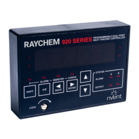
CONTROLLER OPERATOR CONSOLE
Installation and Operation Instructions
Firmware Versions up to and including V3.2x
A
B
M
A R
A L
B
A /
I F T
S H
C K
L O
R A
O G
P R
T R
A T
H E
I E S
E R
0 S
9 2
A T
S T
A R
A L
T P
I G
O U
N F
C O
O R
N I T
M O
R
T E
E N
C K
B A
I N T
P O
A L
R
L L E
D U
R O
L E
N T
A B
C O
M M
I N G
A C
T x
R x
U S
M
U T
Table of Contents

Summary of Contents for Raychem 920 Series
- Page 1 920 SERIES HEAT TRACE CONTROLLER OPERATOR CONSOLE Installation and Operation Instructions Firmware Versions up to and including V3.2x I N T L L E I N G I E S N I T I F T...
- Page 2 2 | nVent.com...
-
Page 3: Table Of Contents
CONTENTS Installation and Maintenance instructions for Firmware Versions up to and including V3.2FX ....4 Certification ..........................4 Limited Warranty .......................... 4 Warranty Exclusion/Disclaimer ....................4 Exclusive Remedies ........................4 Conducted and Radiated Emissions - FCC/DOC Statement of Compliance ......4 Section 1 Overview ........................... -
Page 4: Installation And Maintenance Instructions For Firmware Versions Up To And Including V3.2Fx
INSTALLATION AND MAINTENANCE INSTRUCTIONS FOR FIRMWARE VERSIONS UP TO AND INCLUDING V3.2FX This manual provides information pertaining to the installation, operation, testing, adjustment, and maintenance of the nVent RAYCHEM Model 920 Series Heat Trace Control and Monitoring products. Additional copies of the operating manual may be ordered separately through your nVent representative or online at nVent.com using the document number H56903. -
Page 5: Section 1 Overview
Extended temperature operation permits installation in all but the harshest environments. CSA C/US & FM Approved The 920 Series Operator Console is approved for Class I, Division II, Groups A,B,C,D and Zone 2 hazardous locations making it ideal for direct use in the field. -
Page 6: Section 2 Installation
2.3 OPERATOR SAFETY CONSIDERATIONS The 920 series operator console is suitable for use in Class 1, Division 2, Groups A, B, C, D and Zone 2 hazardous areas. Hazardous areas are defined by Article 500 of the National Electrical Code and Section 18 of the Canadian Electrical Code. -
Page 7: Installation And Removal Procedures
2.6 INSTALLATION AND REMOVAL PROCEDURES 2.6.1 Operator Console Installation and Removal The Operator Console is designed to be easily installed or removed while the Controller is powered - even in Class I Division 2 and Zone 2 hazardous locations. It may be temporarily or permanently installed. -
Page 8: Section 3 User Interface & Operation
The local keypad consists of 6 keys that allow you to select the console mode function that you are interested in. For certain keys, the shift key selects an alternate function, as shown by the text above that key. 920 SERIES PROGRAMMABLE DUAL POINT HEAT TRACING CONTROLLER... -
Page 9: Led Indicators
3.3 LED INDICATORS The console includes twelve LED indicators: Six LEDs indicate the console status — the operating mode (a shifted function, alarm, monitor, or configure modes) and the active control Point (A or B). Four LEDs indicate the alarm and control output status for both Points A and B. The two additional LEDs are used to indicate external communications activity —... -
Page 10: Changing The Configuration
3.4.6 Passcode Protection The 920 Series Dual Point Controller provides a passcode for protection of its configuration. You may view any portion of the configuration with the console “locked”, however, when you attempt to initiate an edit session by pressing , you are prompted to enter the passcode. -
Page 11: Switching Between Points A And B
3.4.7 Switching Between Points A and B There are two LEDs to indicate which point has control of the console. You may switch from Point A to Point B (or vice versa) at any time (except during an edit session) by pressing the A/B key. -
Page 12: Section 4 Operating Modes
SECTION 4 OPERATING MODES 4.1 ALARM MODE The ALARM mode is invoked when you press the SHIFT key followed by the ALARM key. This mode allows you to examine and reset any alarms that may exist. Use ( ) to examine the next (previous) active alarm. 4.1.1 Resetting One Alarm To reset an alarm, press . -
Page 13: Monitor Mode
This sub-menu is used to view minimum and maximum temperatures, total accumulated power, hours in use, and the number of hours since the last time the Controller was reset. These parameters may be reset by the user. For additional information, refer to the 920 Series Heat Trace Controller Manual. -
Page 14: Configure Mode
4.3 CONFIGURE MODE The CONFIGURE mode is selected when the operator presses the SHIFT key followed by the CONFIG key. This mode allows you to examine or alter the Controller’s configuration. Menu items with a trailing “...” indicate an entry point to a sub-menu. To enter a sub-menu, use to position the menu item in the display and then press . -
Page 15: Other Alarms Config
4.3.3 “OTHER ALARMS CONFIG...” Sub-Menu This sub-menu allows the user to set up all alarms that do not directly relate to the temperature sensors. These include all AC alarms (voltage, current. ground fault, etc.) as well as protection settings such as power limiting, etc. Each alarm may be ENAbled or DISabled. -
Page 16: Point Setup
4.3.4 “POINT SETUP...” Sub-Menu The “Point Setup” sub-menu is used to configure parameters that relate directly to each specific control Point (A or B). Note that these settings must be configured for each of the control points that are in use. Included in this menu are control mode settings, circuit breaker and switch ratings, auto-cycle set up parameters, etc.. -
Page 17: Common Setup
4.3.5 “COMMON SETUP...” Sub-Menu The “Common Setup” sub-menu is used to configure parameters that are common to both control Points A and B. These settings are set up only once to define the operation of both control points. CONTROL SETPOINT 20°C LO TS 1 -10°C LO LOAD 1.0 A... -
Page 18: Communications Setup
4.3.6 “COMMUNICATIONS SETUP...” Sub-Menu The settings found in this sub-menu must be configured whenever an optional communications board is installed in the Control Module. These parameters are common to both control points, EXCEPT the “HTCBUS ADDR”, “MODBUS ADDR”, and “MODBUS SUBADDR” parameters, which must be defined for each control point individually. -
Page 19: Section 5 Maintenance
SECTION 5 MAINTENANCE 5.1 OPERATOR MAINTENANCE The 920 Series Operator Console is designed to be a maintenance free product. No regular maintenance should be required. 5.2 REPLACEABLE PARTS There are no user-serviceable parts in the 920 Series Operator Console. The unit is modular and easily changed out in the field in a matter of minutes. - Page 20 ©2018 nVent. All nVent marks and logos are owned or licensed by nVent Services GmbH or its affiliates. All other trademarks are the property of their respective owners. nVent reserves the right to change specifications without notice. Raychem-IM-H56902-920seriesOpConsole-EN-1805...