Honeywell EC7830A Installation Instructions Manual
7800 series
Hide thumbs
Also See for EC7830A:
- Instruction manual (17 pages) ,
- Installation instructions manual (21 pages)
Table of Contents
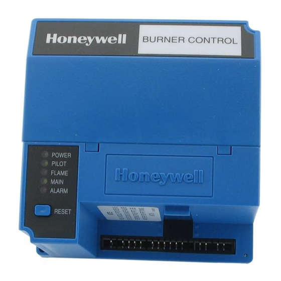
EC7830A, RM7830A, EC7850A, RM7850A
APPLICATION
The Honeywell EC/RM7830A and EC/RM7850A are
microprocessor-based integrated burner controls for
automatically fired gas, oil, or combination fuel single burner
full modulation (EC/RM7850A) or on/off (EC/RM7830A)
applications. The EC/RM7830A; EC/RM7850A system
consists of a relay module, subbase, amplifier, and purge
card. Options include keyboard display module (KDM),
Personal Computer Interface, Data ControlBus Module™,
remote display mounting and Combustion System Manager®
Software.
Functions provided by the EC/RM7830A and EC/RM7850A
include automatic burner sequencing, flame supervision,
system status indication, system or self-diagnostics and
troubleshooting. Text readout on the Keyboard Display Module
is available in English, Spanish, Portuguese, Katakana
(Japanese), French, Chinese, German, and Italian languages.
This document provides installation and static checkout
instructions. Other applicable publications are:
63-2278:
Q7700 Network Interface Unit Product Data.
65-0084:
Q7800A,B 22-Terminal Wiring Subbase
Product Data.
65-0090:
S7800A Keyboard Display Module Product Data.
65-0091:
S7810A Data ControlBus Module™ Product
Data.
65-0228:
S7810B Multi-Drop Switch Module Product Data.
65-0095:
S7820 Remote Reset Module Product Data.
65-0097:
221729C Dust Cover Packing Instructions.
65-0102:
ZM7850A Combustion System Manager®
Operating Instructions.
65-0109:
R7824, R7847, R7848, R7849, R7861, R7886
Flame Amplifiers for the 7800 SERIES
Product Data.
65-0131:
221818A Extension Cable Assembly Product
Data.
65-0229:
7800 SERIES Relay Modules Checkout and
Troubleshooting Product Data.
SPECIFICATIONS
Electrical Ratings (See Tables 3A, 3B, 3C and 3D):
Voltage and Frequency:
RM7830A and RM7850A:
120 Vac (+10/-15%), 50/60 Hz (±10%).
EC7830A and EC7850A:
220/240 Vac (+10%/-15%), 50/60 Hz (±10%)
Power Dissipation: 10W maximum.
Maximum Total Connected Load: 2000 VA.
Fusing Total Connected Load: 20A maximum, type FRN or
equivalent.
® U.S. Registered Trademark
Copyright © 1998 Honeywell Inc. • All Rights Reserved
7800 SERIES Relay Modules
Environmental Ratings:
Ambient Temperature:
Operating: -40°F to 140°F (-40°C to +60°C).
Storage: -40°F to 150°F (-40°C to +66°C).
Humidity: 85% relative humidity continuous,
noncondensing.
Vibration: 0.5G environment.
Approvals:
RM7830A and RM7850A:
Underwriters Laboratories Inc. Listed: File No. MP268,
Canadian Standards Association Certified: LR9S329-3.
Factory Mutual Approved: Report No. J.I.1V9A0.AF.
Industrial Risk Insurers: Acceptable.
Federal Communications Commission: Part 15,
EC7830A and EC7850A: Factory Mutual Approved.
These products also comply with the following European
directives:
Gas Appliance Directive: 90/396/EEC.
Low Voltage Directive: 73/23/EEC.
EMC Directive: 89/336/EEC.
GASTEC: CE-63AP3070/1.
Lloyds Register Approval.
Oil appliances:
EC7830A: DIN-5F 106/96.
EC7850A: DIN-5F 107/96.
These products are approved according to EN298, "Automatic
gas burner systems for gas burners and gas burning
appliances with or without fans."
Please note the following to comply with EN60730 for remote
mounting of the KDM and/or remote reset module. It is
necessary to provide electrical separation using insulation at
least equivalent to double or reinforced insulation. This can be
accomplished by either:
1. Optically isolating the communication and/or remote
reset lines from the control cabinet or
2. Providing physical separation from the communication
and/or remote reset lines using electrical conduit and a
204718a Remote Display Cover Assembly or other
suitable enclosure that meets ip40 class of protection.
INSTALLATION INSTRUCTIONS
Guide No. MCCZ.
Class B, Emissions.
66-1092-2
Table of Contents

Related Manuals for Honeywell EC7830A


Summary of Contents for Honeywell EC7830A
- Page 1 220/240 Vac (+10%/-15%), 50/60 Hz (±10%) Power Dissipation: 10W maximum. Maximum Total Connected Load: 2000 VA. Fusing Total Connected Load: 20A maximum, type FRN or equivalent. ® U.S. Registered Trademark 66-1092-2 Copyright © 1998 Honeywell Inc. • All Rights Reserved...
-
Page 2: Installation
EC7830, RM7830A,EC7850A,RM7850A 7800 SERIES RELAY MODULES 9. This equipment generates, uses and can radiate INSTALLATION radio frequency energy and, if not installed and used in accordance with the instructions, can cause When Installing this Product… interference with radio communications. It has been tested and found to comply with the limits for a Class B computing device of Part 15 of FCC rules, which 1. - Page 3 RESET INTERNAL WIRING 120 VAC, 50/60 Hz POWER SUPPLY, RM7830A; 220-240 VAC, 50/60 Hz POWER SUPPLY, EC7830A. PROVIDE DISCONNECT MEANS AND OVERLOAD PROTECTION AS REQUIRED. TO CONNECT L1 DIRECTLY TO LOS, AT LEAST ONE CONTROLLED SHUTDOWN MUST BE PROVIDED EVERY 24 HOURS.
- Page 4 EC7830, RM7830A,EC7850A,RM7850A 7800 SERIES RELAY MODULES HOT N CONFIGURATION PLUG-IN PURGE TIMER CARD JUMPERS TEST FLAME SIGNAL JACK RUN/TEST SWITCH PLUG-IN MICROCOMPUTER FLAME AMPLIFIER RESET SHUTTER PUSHBUTTON RELAY DRIVE CIRCUIT RELAY STATUS FEEDBACK AND LINE VOLTAGE INPUTS SAFETY RELAY STATUS CIRCUIT LEDS CONTROL...
- Page 5 FLAME DETECTOR 1 12O VAC, 50/60 Hz POWER SUPPLY (RM7830A). 220-240 VAC, 50/60 Hz POWER SUPPLY (EC7830A). PROVIDE DISCONNECT MEANS AND OVERLOAD PROTECTION AS REQUIRED. SEE FLAME DETECTOR INSTRUCTIONS FOR CORRECT WIRING. EC/RM7830A Power Burner ON/OFF, GAS or OIL Sequence...
- Page 6 EC7830, RM7830A,EC7850A,RM7850A 7800 SERIES RELAY MODULES LEGEND SERIES 90 SERIES 90 FIRING RATE ALARM CONTROLLER Q7800 MOTOR (NORMALLY OPEN) HIGH FIRE LOW FIRE SWITCH INPUT COMMON PREIGNITION INTERLOCK INPUT MODULATE HIGH FIRE SWITCH INPUT LOW FIRE BURNER/BLOWER (L1) MOTOR IGNITION LINE VOLTAGE SUPPLY LOCKOUT INPUT AIRFLOW SWITCH INPUT...
- Page 7 EC7830, RM7830A,EC7850A,RM7850A 7800 SERIES RELAY MODULES Table 1. Recommended Wire Sizes and Part Numbers. Application Recommended Wire Size Recommended Part Numbers Line voltage terminals 14, 16, or 18 AWG copper conductor, 600 TTW60C, THW75C, THHN90C. volt insulation, moisture-resistant wire. 22 AWG two-wire twisted pair with Belden 8723 shielded cable or ground, or five-wire.
- Page 8 Shutter drive for dynamic self-check flame sensor. See Table 2. Honeywell has tested this output at 9.8A at PF = 0.5, 58.8A inrush for 100,000 cycles (EN298 approval does not require this test). 2000 VA maximum connected load to relay module.
- Page 9 See Table 2. 2000 VA maximum connected load to relay module. Honeywell has tested this output at 9.8A at PF = 0.5, 58.8A inrush for 100,000 cycles (EN298 approval does not require this test). Total load current, excluding Burner/Boiler Motor and Firing Rate Outputs cannot exceed 5A, 25A inrush.
- Page 10 EC7830, RM7830A,EC7850A,RM7850A 7800 SERIES RELAY MODULES Table 3D. EC7850A Terminal Ratings. Terminal No. Abbreviation Description Ratings Flame Sensor Ground Earth G Earth Ground Line Voltage Common(Neutral) Alarm (Normally Open) 220/230/240 Vac, 1A, 10A inrush for 5000 cycles. Line Voltage Supply (L1) 220 to 240 Vac (+10/-15%), 50/60 Hz (±10%).
-
Page 11: General Instructions
EC7830, RM7830A,EC7850A,RM7850A 7800 SERIES RELAY MODULES Use extreme care when testing the system. Line voltage is General Instructions present on most terminal connections when power is on. Ensure proper selection of configuration jumpers before 1. Perform all applicable tests listed in the Static starting the burner operation. - Page 12 EC7830, RM7830A,EC7850A,RM7850A 7800 SERIES RELAY MODULES Table 4. EC/RM7830A Static Checkout (continued) If Operation is Abnormal , Test No. Test Jumpers Voltmeter Normal Operation Check the Items Listed Below 5-21 Same as test no. 8 for connections Same as test no. 8. If using direct to terminal 8.
-
Page 13: Principal Technical Features
EC7830, RM7830A,EC7850A,RM7850A 7800 SERIES RELAY MODULES Table 5. EC/RM 7850A Static Checkout (continued). Test Test If Operation is Abnormal, Jumpers Voltmeter Normal Operation Check These Items Firing rate motor drives closed; zero volts at 1. Low Fire Start Switch. 14-13 19-L2 terminal 19 after motor starts driving closed. -
Page 14: Operation
EC7830, RM7830A,EC7850A,RM7850A 7800 SERIES RELAY MODULES 6. PILOT STAB. PERIOD restarts. If the condition is not corrected and the hold Lockout Input opens during PILOT STAB. condition exists for four minutes, the relay module locks out. Airflow Switch opens during PILOT STAB. Causes for hold conditions in the INITIATE sequence: Low Fire Switch opens (EC/RM7850A). - Page 15 EC7830, RM7830A,EC7850A,RM7850A 7800 SERIES RELAY MODULES WIRING SUBBASE RUN/TEST SWITCH H O N E Y W E LL RELAY MODULE CONFIGURATION JUMPERS PURGE TIMER SEQUENCE STATUS LED PANEL RESET BUTTON CAPTIVE MOUNTING DUST SCREW COVER FLAME AMPLIFIER M15187A Fig. 5. EC/RM7830A and EC/RM7850A Relay Modules exploded view. 4.
-
Page 16: Settings And Adjustments
For further checkout and troubleshooting, see form 65-0229. Home and Building Control Home and Building Control Honeywell Inc. Honeywell Limited-Honeywell Limitée Honeywell Plaza 155 Gordon Baker Road P.O. Box 524 North York, Ontario Minneapolis MN 55408-0524 M2H 3N7 Printed in U.S.A.