RM7895A,B,C,D/EC7895A,C;
RM7896A,C,D
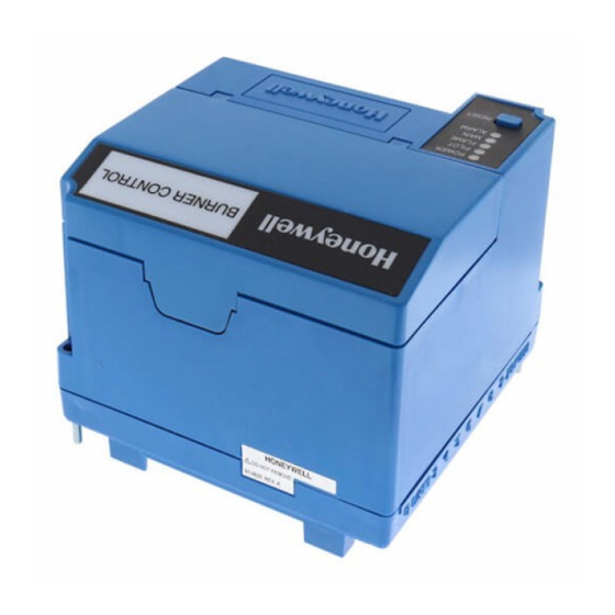
7800 SERIES Relay Modules
APPLICATION
The RM7895A,B,C,D/EC7895A,C; RM7896A,B,C,D are
microprocessor-based integrated burner controls for
automatically fired gas, oil, or combination fuel single
burner applications. They are intended to replace the
R4795 and R7795 Primary Controls. The
RM7895A,B,C,D/EC7895A,C; RM7896A,B,C,D systems
consist of a relay module, subbase, amplifier, and purge
card. Options include: 2-line VFD (see document 65-
0090-6) or 4-line LCD (see document 32-00110-01)
Keyboard Display Module, Personal Computer Interface,
Data ControlBus™ Module, remote display mounting,
expanded annunciator and Combustion System Manager®
Software.
Functions provided by the RM7895A,B,C,D/EC7895A,C;
RM7896A,B,C,D include automatic burner sequencing,
flame supervision, system status indication, system or
self-diagnostics and troubleshooting. The RM7896
provides a postpurge function.
This document covers the following 7800 Series Relay
Modules:
• RM7895A1014
• RM7895A1048
• RM7895B1013
• RM7896A1012
• RM7895A2014
• RM7895A2048
• RM7895B2013
• RM7896A2012
• RM7895C1020
• RM7895C1012
• RM7895D1011
• RM7896C1010
• RM7896D1019
• RM7895C2020
• RM7895C2012
• RM7895D2011
• RM7896C2010
• RM7896D2019
• EC7895A1010
• EC7895A2010
• EC7895C1000
• EC7895C2000
SIL
Capable
3
INSTALLATION INSTRUCTIONS
This document provides installation and static checkout
instructions. Other applicable publications are:
Publication
No.
32-00110
S7800A2142 4-line LCD Keyboard
Display Module Product Data
63-2278
Q7700 Network Interface Unit Product
Data
65-0084
Q7800A,B 22-Terminal Wiring Subbase
Product Data
65-0090
S7800A1142 2-line VF Keyboard Display
Module Product Data
65-0091
S7810A Data ControlBus Module™
Product Data
65-0095
S7820 Remote Reset Module Product
Data
65-0097
221729C Dust Cover Packing
Instructions
65-0101
S7830 Expanded Annunciator Product
Data
65-0102
ZM7850A Combustion System Manager™
Operating Instructions
65-0109
R7824, R7847, R7848, R7849, R7851,
R7861, R7886 Flame Amplifiers for the
7800 Series Product Data
65-0131
221818A Extension Cable Assembly
Product Data
65-0229
7800 SERIES Relay Modules Checkout
and Troubleshooting Product Data.
65-0092
QS7800A ControlBus™ Module, Standard
65-0227
QS7800B ControlBus™ Module,
Multidrop
SPECIFICATIONS
Electrical Ratings (See Table 3):
Voltage and Frequency:
RM7895/RM7896: 120 Vac (+10/-15%), 50/60 Hz (±
10%).
EC7895A,C: 220/240 Vac (+10%/-15%), 50/60 Hz
(±10%)
Power Dissipation: 10W maximum.
Maximum Total Connected Load: 2000 VA.
Product
32-00156-01
Table of Contents

Related Manuals for Honeywell RM7895A1014


Summary of Contents for Honeywell RM7895A1014
- Page 1 221729C Dust Cover Packing provides a postpurge function. Instructions This document covers the following 7800 Series Relay 65-0101 S7830 Expanded Annunciator Product Modules: Data • RM7895A1014 65-0102 ZM7850A Combustion System Manager™ • RM7895A1048 Operating Instructions • RM7895B1013 65-0109 R7824, R7847, R7848, R7849, R7851, •...
-
Page 2: Installation
RM7895A,B,C,D/EC7895A,C; RM7896A,C,D 7800 SERIES RELAY MODULES Fusing Total Connected Load: 15A Fast Blow, type SC or 2. Wiring must comply with all applicable codes, equivalent. ordinances and regulations. 3. Wiring must comply with NEC Class 1 (Line Voltage) wir- Environmental Ratings: ing. - Page 3 RM7895A,B,C,D/EC7895A,C; RM7896A,C,D 7800 SERIES RELAY MODULES Mounting Wiring Subbase Any relay module in the new 2000 series will only be able to be installed on subbase Q7800A2005/U, and will not be 1. Mount the subbase in any position except horizon- backward compatible with any Q7800A1005/U legacy tally with the bifurcated contacts pointing down.
- Page 4 RM7895A,B,C,D/EC7895A,C; RM7896A,C,D 7800 SERIES RELAY MODULES (HOT) PROVIDE DISCONNECT MEANS AND RM7895, RM7896: 120 VAC, 50/60 HZ. OVERLOAD PROTECTION AS REQUIRED. EC7895A,C: 220-240 VAC, 50/60 HZ. LOCKOUT IF JUMPER JR2 REMOVED. PLUG-IN PURGE CONFIGURATION TIMER CARD JUMPERS TEST FLAME SIGNAL JACK RUN/TEST SWITCH...
- Page 5 RM7895A,B,C,D/EC7895A,C; RM7896A,C,D 7800 SERIES RELAY MODULES Q7800 FOR DIRECT SPARK IGNITION (OIL OR GAS) IGNITION TRANSFORMER LINE VOLTAGE ALARM MAIN VALVE BURNER MOTOR (BLOWER) (L1) BURNER CONTROLLER/LIMITS LOCKOUT INTERLOCK (INCLUDING AIRFLOW SWITCH) INTERMITTENT PILOT/IGNITION MAIN FUEL VALVE(S) IGNITION MASTER FLAME DETECTOR SWITCH (HOT) TIMED...
- Page 6 RM7895A,B,C,D/EC7895A,C; RM7896A,C,D 7800 SERIES RELAY MODULES Q7800 FOR DIRECT SPARK IGNITION (OIL OR GAS) IGNITION TRANSFORMER LINE VOLTAGE ALARM MAIN VALVE BURNER MOTOR (BLOWER) (L1) BURNER CONTROLLER/LIMITS LOCKOUT INTERLOCK (INCLUDING AIRFLOW SWITCH). 10 SEC. INTERRUPTED PILOT/IGNITION MAIN FUEL VALVE(S) DELAYED (2ND STAGE) IGNITION MAIN VALVE...
- Page 7 RM7895A,B,C,D/EC7895A,C; RM7896A,C,D 7800 SERIES RELAY MODULES Table 1. Recommended Wire Sizes and Part Numbers. Application Recommended Wire Size Recommended Part Numbers Line voltage terminals. 14, 16 or 18 AWG copper conductor, 600 volt insulation, TTW60C, THW75C, THHN90C. moisture-resistant wire. Keyboard Display Module 22 AWG two-wire twisted pair with ground, or five-wire.
- Page 8 RM7895A,B,C,D/EC7895A,C; RM7896A,C,D 7800 SERIES RELAY MODULES Table 3. Terminal Ratings. Termina Ratings Number Description RM7895/RM7896 EC7895 Flame Sensor Ground — — Earth G — — Earth Ground L2(N) Line Voltage Common — — Alarm 120 Vac, 1A pilot duty. 220-240 Vac, 1A pilot duty. Burner Motor 120 Vac, 9.8A AFL, 58.8 ALR 220-240 Vac, 4A at PF = 0.5, 20A inrush.
-
Page 9: General Instructions
RM7895A,B,C,D/EC7895A,C; RM7896A,C,D 7800 SERIES RELAY MODULES STATIC CHECKOUT Equipment Recommended 1. Voltmeter (1M ohm/volt minimum sensitivity) set on After checking all wiring, perform this checkout before the 0 to 300 Vac scale. installing the 2. Two jumper wires, no. 14 wire, insulated, 12 in. EC7895A,C/RM7895A,B,C,D/RM7896A,B,C,D on the (304.8 mm) long with insulated alligator clips at subbase. -
Page 10: Principal Technical Features
RM7895A,B,C,D/EC7895A,C; RM7896A,C,D 7800 SERIES RELAY MODULES Table 6. Static Checkout. (Continued) Relay Test Module Test If Operation is Abnormal, Number Model Jumpers Voltmeter Normal Operation Check Items Listed Below — 1. Ignition spark (if ignition 1. Watch for spark or listen for buzz. transformer is connected to 2. - Page 11 RM7895A,B,C,D/EC7895A,C; RM7896A,C,D 7800 SERIES RELAY MODULES SUBBASE Q7800A1005/U SHOWN WIRING SUBBASE RUN/TEST (C,D ONLY) SWITCH H O N E Y W E LL RELAY MODULE CONFIGURATION JUMPERS PURGE TIMER SEQUENCE STATUS LED PANEL POWE R RESET PILOT BUTTON FLAM E MAIN ALARM CAPTIVE...
-
Page 12: Sequence Of Operation
RM7895A,B,C,D/EC7895A,C; RM7896A,C,D 7800 SERIES RELAY MODULES g. Internal system fault occurred. seconds to thirty minutes with power applied and the h. Purge card is removed. operating control indicating a call for heat. Purge card is bad. 1. The Airflow Interlock, burner switch, Run/Test switch 6. -
Page 13: Settings And Adjustments
RM7895A,B,C,D/EC7895A,C; RM7896A,C,D 7800 SERIES RELAY MODULES Run/Test Switch (RM/EC7895C,D; SELECTABLE CONFIGURATION JUMPERS RM7896C,D only) RUN/TEST SWITCH (EC7895C; RM7895C,D; RM7896C,D) The Run/Test Switch is located on the top side of the relay module, see Fig. 5. The Run/Test Switch allows the burner sequence to be altered as follows: 1. -
Page 14: License Agreement
RM7895A,B,C,D/EC7895A,C; RM7896A,C,D 7800 SERIES RELAY MODULES Modbus & DDL Interface security Modbus RS-485 & DDL protocols do not support security features. For DDL interface - only DDL devices shall be Any conducts critical to device functionality (DDL, connected to the Burner Controller DDL line. Modbus lines etc.) shall be physically protected (installed outside public access) since they could be damaged or License agreement... - Page 15 RM7895A,B,C,D/EC7895A,C; RM7896A,C,D 7800 SERIES RELAY MODULES 32-00156—01...
- Page 16 RM7895A,B,C,D/EC7895A,C; RM7896A,C,D 7800 SERIES RELAY MODULES For More Information The Honeywell Thermal Solutions family of products includes Honeywell Combustion Safety, Eclipse, Exothermics, Hauck, Kromschröder and Maxon. To learn more about our products, visit ThermalSolutions.honeywell.com or contact your Honeywell Sales Engineer.