Table of Contents
Quick Links
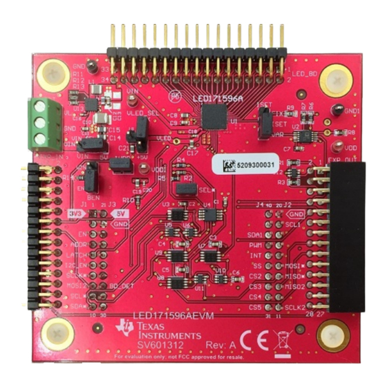
Using the LED171596AEVM Evaluation Module
The Texas Instruments LED171596A evaluation module (EVM) helps designers evaluate the operation
and performance of the LED171596A 96-LED driver. The LED171596A is an LED matrix driver that can
individually control up to 96 LEDs. To control the 96 LEDs it uses four high-side PMOS switches and 24
low-side programmable current sinks. The driver has 9-bit duty cycle and 8-bit current control of each low
side LED current sink. They can be individually controlled through the I2C-compatible or SPI interface.
The EVM contains one LED171596A (see
TIVA
EK-TM4C123GXL
...................................................................................................................
1
..........................................................................................................................
2
2.1
2.2
3
3.1
3.2
3.3
3.4
3.5
3.6
3.7
3.8
3.9
3.10
3.11
3.12
4
...................................................................................................................
5
6
1
2
3
4
5
6
7
8
9
10
11
12
13
Submit Documentation Feedback
Launchpad, NOT included in the EVM kit, is required to run the GUI software.
............................................................................................................
................................................................................................................
.................................................................................
.......................................................................................
.........................................................................................
............................................................................................
..........................................................................................................
.........................................................................................................
...................................................................................................
......................................................................................................
.......................................................................................................
................................................................................................................
.....................................................................................................
...........................................................................................................
.............................................................................................................
......................................................................................................
..............................................................................................................
...................................................................................................
.........................................................................................
Copyright © 2017-2018, Texas Instruments Incorporated
SNVU546C - October 2017 - Revised May 2018
Table
1) and one LEDARRAYEVM with 96 white LEDs. The
Contents
..............................................................................
..................................................................
......................................................................
.....................................................................
List of Figures
........................................................
....................................................
..............................................................................
..................................................................
.........................................................
.................................................................
.......................................................
Using the LED171596AEVM Evaluation Module
User's Guide
3
3
3
4
4
5
5
7
7
8
8
10
10
11
11
12
13
25
30
32
4
4
5
5
6
7
7
7
7
8
8
9
10
1
Table of Contents

Related Manuals for Texas Instruments LED171596AEVM


Summary of Contents for Texas Instruments LED171596AEVM
-
Page 1: Table Of Contents
SNVU546C – October 2017 – Revised May 2018 Using the LED171596AEVM Evaluation Module The Texas Instruments LED171596A evaluation module (EVM) helps designers evaluate the operation and performance of the LED171596A 96-LED driver. The LED171596A is an LED matrix driver that can individually control up to 96 LEDs. - Page 2 Schematic Page2 Trademarks Tiva is a trademark of Texas Instruments. Stellaris is a registered trademark of Texas Instruments. Windows is a registered trademark of Microsoft Corporation. All other trademarks are the property of their respective owners. Using the LED171596AEVM Evaluation Module SNVU546C –...
-
Page 3: Introduction
J4-1 and J4-2 for normal operation (VLED supplied by TPS62140). • VEXT (J7) – is provided to connect an external supply to The LED171596AEVM. Use J7-3 (VIN) and J7-2 (GND) to supply power to the TPS62140. Use J7-1 (VL) and J7-2 (GND) when using external supply for VLED power. -
Page 4: Operation
Figure Figure 2. Set Jumper Pins EVM Software EVM software is available for download from the website. The LED171596AEVM is connected via USB to the computer and controlled with special EVM software (Windows 7/10 compatible). An EK- ® TM4C123GXL, Tiva™ LaunchPad (http://www.ti.com/tool/ek-tm4c123gxl), is used with the EVM to provide I2C/SPI communication, and external PWM, EN, IFSEL/LATCH pin control with the LED171596A via USB. -
Page 5: Minimum Procedure For Turning On The Leds
The minimum procedure for turning on the LEDs is as follows: 1. Set the Power Select Switch on Tiva LaunchPad to debug (refer to Figure 2. Connect the LaunchPad board to the LED171596AEVM board (refer to Figure 3. Verify jumper pin setting (refer to Figure 4. -
Page 6: Connect Evaluation Board And Launchpad
Figure Figure 5. Connect Evaluation Board and LaunchPad Connect external power and ground to the EVM board (BOOSTXL-LED171596A). Using the LED171596AEVM Evaluation Module SNVU546C – October 2017 – Revised May 2018 Submit Documentation Feedback Copyright © 2017–2018, Texas Instruments Incorporated... -
Page 7: Tiva Icdi Driver Installation In Windows 7
Figure 8. Win10 Stellaris Virtual Serial Port on Device Manager Figure 9. Win10 Stellaris In-Circuit Debug Interface on Device Manager SNVU546C – October 2017 – Revised May 2018 Using the LED171596AEVM Evaluation Module Submit Documentation Feedback Copyright © 2017–2018, Texas Instruments Incorporated... -
Page 8: Programming The Firmware
“Configuration tab” (refer to Figure 10). Then select “Program” tab; navigate to the folder where GUI is installed. By default installation, it should be “C:\Program Files (x86)\Texas Instruments\LED171596A EVM”, select tivafw.bin and click the [Program Button]. Figure 10. LM Flash Programmer EVM Software Installation Execute setup_LED171596A_EVM.msi file: If it is compressed in zip file format, unzip first in any location... -
Page 9: Setup Led171596A Evm
Check to accept the agreement and click “Next” button to proceed with installation. Click “Next” button. By default, program will be installed in C:\Program Files (x86)\Texas Instruments\LED171596A folder and Texas Instruments\LED171596AEVM in start menu. Click ‘Next’” button to proceed with installation. -
Page 10: Evm Software Launch
Figure 13. LED171596AEVM Setup Wizard EVM Software Launch Run ‘C:\Program Files (x86)\Texas Instruments\ LED171596A EVM\LED171596A_EVM.exe’ if default installation folder was not modified in the “EVM software installation” step or click the desktop icon “LED171596A EVM”. Figure 14. Desktop Icon... -
Page 11: Main Menu
The Information view is shown when EVM software is started or ‘Info’ icon is clicked, and it provides brief information of the LED171596A. For more detail information, refer to the LED171596A datasheet. Figure 17. Information View SNVU546C – October 2017 – Revised May 2018 Using the LED171596AEVM Evaluation Module Submit Documentation Feedback Copyright © 2017–2018, Texas Instruments Incorporated... -
Page 12: Register View
The register view is shown when ‘Register’ icon is clicked, and it provides the register values, field values, and descriptions. Figure 18. Register View (Collapsed) Figure 19. Register View (Expanded) Using the LED171596AEVM Evaluation Module SNVU546C – October 2017 – Revised May 2018 Submit Documentation Feedback Copyright © 2017–2018, Texas Instruments Incorporated... -
Page 13: Control Menu
Differently to the Registers view control, the Control view does not provides deferred mode but provides immediately mode only. Figure 20. Control View (Control Tab) SNVU546C – October 2017 – Revised May 2018 Using the LED171596AEVM Evaluation Module Submit Documentation Feedback Copyright © 2017–2018, Texas Instruments Incorporated... -
Page 14: I2C/Spi Selection
LED current trackbar/text. There are buttons and texts, which are ordered in the same order as the LEDs on the LED171596AEVM. Simply, a LED can be turned on or turned off is available when a button is clicked. Brightness 0 is written into the LEDxx_BRI(0x160 + LED number) reigster when the LED is turned off, LED brightness/current values configured by trackbars are written to LEDxx_BRI(0x160 + LED number) register and LEDxx_CUR(0x100+LED number) register at once. -
Page 15: Led On/Off Control
LEDs marked in red are updated when the update button is clicked. It turns back to normal mode if a button clicked without Left-Ctrl key. Figure 24. LED Brightness or Current Control SNVU546C – October 2017 – Revised May 2018 Using the LED171596AEVM Evaluation Module Submit Documentation Feedback Copyright © 2017–2018, Texas Instruments Incorporated... -
Page 16: Led Setting Values
LED Group registers(0x1DE – 0x1F1) can be set through the “Group Selection” pop-up window shown when “Group Set” button is clicked. Figure 26. Group Set Button Using the LED171596AEVM Evaluation Module SNVU546C – October 2017 – Revised May 2018 Submit Documentation Feedback... -
Page 17: Group Selection
LED Disable registers(0x1C1 – 0x1CC) can be set through the “Disable Selection” pop-up window shown when “Disable Set” button is clicked. Figure 29. Display Disable Set Button SNVU546C – October 2017 – Revised May 2018 Using the LED171596AEVM Evaluation Module Submit Documentation Feedback Copyright © 2017–2018, Texas Instruments Incorporated... -
Page 18: Disabled Selection
Figure 30. Disabled Selection LED Buttons for disable selection are ordered in the same order as the LEDs on the LED171596AEVM and current disable selection value is displayed on the button. To change disable selection value, select the LED or LEDs and then click “Disable” or “Enable” button. The newly configured values are transferred to the EVM when “Done”... -
Page 19: Sloper Selection
Figure 33. Sloper Set Button LED Buttons for sloper selection are ordered in the same order as the LEDs on the LED171596AEVM and current sloper selection value is displayed on the button. To change sloper selection value, select the LED or LEDs and then click “UnSloper”... -
Page 20: Sw Latch And Auto Latch Selection
Figure 38. Enable Bit Control 3.12.12 LED Driver Control the LED driver group box provides information and control of LED_DRIVER_CONTROL Register (0x21). Using the LED171596AEVM Evaluation Module SNVU546C – October 2017 – Revised May 2018 Submit Documentation Feedback Copyright © 2017–2018, Texas Instruments Incorporated... -
Page 21: Led Driver Register Information
PWM frequency and duty can be controlled when “update” button is pressed. Frequencies from 100 Hz to 20 kHz are available. SNVU546C – October 2017 – Revised May 2018 Using the LED171596AEVM Evaluation Module Submit Documentation Feedback Copyright © 2017–2018, Texas Instruments Incorporated... -
Page 22: External Pwm
Figure 44. Master Sloper Setting 3.12.15 Status Register The Status group box provides the information of STATUS (0x3) register. Using the LED171596AEVM Evaluation Module SNVU546C – October 2017 – Revised May 2018 Submit Documentation Feedback Copyright © 2017–2018, Texas Instruments Incorporated... -
Page 23: 3.12.16 Interrupt Status/Mask/Clear
The Log tab provides the commands that have been sent to EVM and status of evaluation software. Displayed logs can be cleared by clicking the button, ‘Clear’. Figure 47. Log SNVU546C – October 2017 – Revised May 2018 Using the LED171596AEVM Evaluation Module Submit Documentation Feedback Copyright © 2017–2018, Texas Instruments Incorporated... -
Page 24: 3.12.18 Console
‘help’ and pressing Enter Key. Predefined macro file can be loaded and run through clicking the button, ‘Load File’, and the default folder path is “C:\Users\[ID]\Documents\Texas Instruments\LED171596A\LED171596A”. Figure 48. Console Using the LED171596AEVM Evaluation Module SNVU546C – October 2017 – Revised May 2018 Submit Documentation Feedback Copyright © 2017–2018, Texas Instruments Incorporated... -
Page 25: Board Layout
Board Layout www.ti.com Board Layout Figure 49. Top Assembly Layer SNVU546C – October 2017 – Revised May 2018 Using the LED171596AEVM Evaluation Module Submit Documentation Feedback Copyright © 2017–2018, Texas Instruments Incorporated... -
Page 26: Top Layer Routing
Board Layout www.ti.com Figure 50. Top Layer Routing Using the LED171596AEVM Evaluation Module SNVU546C – October 2017 – Revised May 2018 Submit Documentation Feedback Copyright © 2017–2018, Texas Instruments Incorporated... -
Page 27: Mid Layer 1 Routing
Board Layout www.ti.com Figure 51. Mid Layer 1 Routing SNVU546C – October 2017 – Revised May 2018 Using the LED171596AEVM Evaluation Module Submit Documentation Feedback Copyright © 2017–2018, Texas Instruments Incorporated... -
Page 28: Mid Layer 2 Routing
Board Layout www.ti.com Figure 52. Mid Layer 2 Routing Using the LED171596AEVM Evaluation Module SNVU546C – October 2017 – Revised May 2018 Submit Documentation Feedback Copyright © 2017–2018, Texas Instruments Incorporated... -
Page 29: Bottom Layer Routing
Board Layout www.ti.com Figure 53. Bottom Layer Routing SNVU546C – October 2017 – Revised May 2018 Using the LED171596AEVM Evaluation Module Submit Documentation Feedback Copyright © 2017–2018, Texas Instruments Incorporated... -
Page 30: Schematic
Schematic www.ti.com Schematic Figure 54. Schematic Page1 Using the LED171596AEVM Evaluation Module SNVU546C – October 2017 – Revised May 2018 Submit Documentation Feedback Copyright © 2017–2018, Texas Instruments Incorporated... -
Page 31: Schematic
Schematic www.ti.com Figure 55. Schematic Page2 SNVU546C – October 2017 – Revised May 2018 Using the LED171596AEVM Evaluation Module Submit Documentation Feedback Copyright © 2017–2018, Texas Instruments Incorporated... -
Page 32: Bill Of Materials (Bom)
TP Memory Digital Rheostat, MSOP-10 Ultra-Configurable Multiple-Function U3, U7, U8, U9 DCT0008A SN74LVC1G99DCTR Texas Instruments Gate With 3-State Output, DCT0008A Using the LED171596AEVM Evaluation Module SNVU546C – October 2017 – Revised May 2018 Submit Documentation Feedback Copyright © 2017–2018, Texas Instruments Incorporated... - Page 33 Bill of Materials (BOM) www.ti.com Table 2. LED171596AEVM BOM (continued) PACKAGE DESIGNATOR QTY. VALUE DESCRIPTION PART NUMBER MANUFACTURER REFERENCE Dual Bidirectional I2C Bus and SMBus Repeater, 2 Channel Width, 2.3 to 3.6 DGK0008A PCA9515BDGKR Texas Instruments V, -40 to 85 degC, 8-pin MSOP (DGK), Green (RoHS &...
-
Page 34: Revision History
Changed Instructions for Windows 7 Tiva ICDI driver installation ..............• Added Instructions for Windows 10 Tiva ICDI driver installation .................... • Added Programming firmware instructions. Revision History SNVU546C – October 2017 – Revised May 2018 Submit Documentation Feedback Copyright © 2017–2018, Texas Instruments Incorporated... - Page 35 ....................Page ......• Updated Figure 49 through Figure 55 Table 2 for A version of EVM (previous version was E1) SNVU546C – October 2017 – Revised May 2018 Revision History Submit Documentation Feedback Copyright © 2017–2018, Texas Instruments Incorporated...
- Page 36 STANDARD TERMS FOR EVALUATION MODULES Delivery: TI delivers TI evaluation boards, kits, or modules, including any accompanying demonstration software, components, and/or documentation which may be provided together or separately (collectively, an “EVM” or “EVMs”) to the User (“User”) in accordance with the terms set forth herein.
- Page 37 FCC Interference Statement for Class B EVM devices NOTE: This equipment has been tested and found to comply with the limits for a Class B digital device, pursuant to part 15 of the FCC Rules. These limits are designed to provide reasonable protection against harmful interference in a residential installation.
- Page 38 【無線電波を送信する製品の開発キットをお使いになる際の注意事項】 開発キットの中には技術基準適合証明を受けて いないものがあります。 技術適合証明を受けていないもののご使用に際しては、電波法遵守のため、以下のいずれかの 措置を取っていただく必要がありますのでご注意ください。 1. 電波法施行規則第6条第1項第1号に基づく平成18年3月28日総務省告示第173号で定められた電波暗室等の試験設備でご使用 いただく。 2. 実験局の免許を取得後ご使用いただく。 3. 技術基準適合証明を取得後ご使用いただく。 なお、本製品は、上記の「ご使用にあたっての注意」を譲渡先、移転先に通知しない限り、譲渡、移転できないものとします。 上記を遵守頂けない場合は、電波法の罰則が適用される可能性があることをご留意ください。 日本テキサス・イ ンスツルメンツ株式会社 東京都新宿区西新宿6丁目24番1号 西新宿三井ビル 3.3.3 Notice for EVMs for Power Line Communication: Please see http://www.tij.co.jp/lsds/ti_ja/general/eStore/notice_02.page 電力線搬送波通信についての開発キットをお使いになる際の注意事項については、次のところをご覧ください。http:/ /www.tij.co.jp/lsds/ti_ja/general/eStore/notice_02.page 3.4 European Union 3.4.1 For EVMs subject to EU Directive 2014/30/EU (Electromagnetic Compatibility Directive): This is a class A product intended for use in environments other than domestic environments that are connected to a low-voltage power-supply network that supplies buildings used for domestic purposes.
- Page 39 Notwithstanding the foregoing, any judgment may be enforced in any United States or foreign court, and TI may seek injunctive relief in any United States or foreign court. Mailing Address: Texas Instruments, Post Office Box 655303, Dallas, Texas 75265 Copyright © 2018, Texas Instruments Incorporated...
- Page 40 IMPORTANT NOTICE FOR TI DESIGN INFORMATION AND RESOURCES Texas Instruments Incorporated (‘TI”) technical, application or other design advice, services or information, including, but not limited to, reference designs and materials relating to evaluation modules, (collectively, “TI Resources”) are intended to assist designers who are developing applications that incorporate TI products;...