Allen-Bradley PowerFlex 525 Installation Instructions
Incremental encoder input
Hide thumbs
Also See for PowerFlex 525:
- User manual ,
- Original instructions manual (48 pages) ,
- Application technique (24 pages)
Quick Links
See also:
User Manual
Installation Instructions
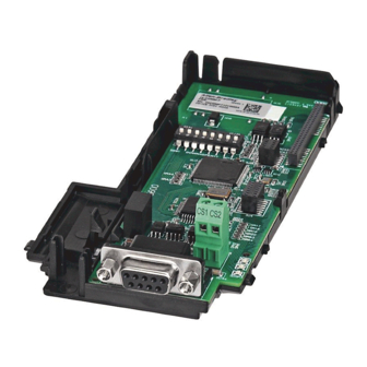
PowerFlex 525 Incremental Encoder Input
Catalog Number: 25-ENC-1
Control Module
Back Cover
Mount the Incremental Encoder onto the
3
Control Module Back Cover
Mounting catch
Note: Incremental Encoder Input is for PowerFlex 525 only.
You can install both the communication adapter and optional
Incremental Encoder Input on the same Control Module Back Cover.
Publication 520-IN009C-EN-P - July 2014
1
Incremental
Encoder Input
2
Voltage DIP switch
4
L1
L2
L3
I
O
0V
DC+ DC–
0V
Lock the Incremental Encoder onto the
Control Module Back Cover
Wait three minutes
after shutdown for
capacitors to discharge
to safe voltage levels.
Locking tab

Related Manuals for Allen-Bradley PowerFlex 525


Summary of Contents for Allen-Bradley PowerFlex 525
-
Page 1: Installation Instructions
Control Module Back Cover Mounting catch Locking tab Note: Incremental Encoder Input is for PowerFlex 525 only. You can install both the communication adapter and optional Incremental Encoder Input on the same Control Module Back Cover. Publication 520-IN009C-EN-P - July 2014... - Page 2 (1) If Encoder requires 24V power, it must be supplied by an to SHLD external power source. U.S. Allen-Bradley Drives Technical Support - Tel: (1) 262.512.8176, Fax: (1) 262.512.2222, E-mail: [email protected] Online: www.ab.com/support/abdrives Allen-Bradley, Rockwell Software, Rockwell Automation, PowerFlex, and TechConnect are trademarks of Rockwell Automation, Inc.