
Related Manuals for Bosch ARD-FPBEPPR-OC

Summary of Contents for Bosch ARD-FPBEPPR-OC
- Page 1 BioEntry Plus ARD-FPBEPPR-OC | ARD-FPBEPHP-OC ARD-FPBEPIC-OC | ARD-FPBEPMF-OC Installation manual...
-
Page 3: Table Of Contents
How to place a finger Product Contents Description Product Dimension Cables and Connectors Installation of Wall-mount Bracket Connections Power Connection Ethernet Connection RS485 Connections Relay Connection Digital Input Connection Wiegand I/O Connection Bosch Access Systems GmbH Installation manual | V 1.1 | 2010.10... -
Page 4: En | Table Of Contents
| Table of Contents BioEntry Plus Network Default Setting Installation References Electrical Specification Troubleshooting Device Cleaning FCC Rules Specifications Index | V 1.1 | 2010.10 Installation manual Bosch Access Systems GmbH... -
Page 5: Safety Precautions
Do not let children touch the device without supervision. – Do not use the device for any other purpose than specified. – Contact your nearest dealer in case of a trouble or problem. Bosch Access Systems GmbH Installation manual | V 1.1 | 2010.10... -
Page 6: Basics Of Fingerprint Recognition
To avoid privacy concern, the fingerprints are not save itself. It is impossible to reconstruct a fingerprint image from a fingerprint template which is just numeric data of the features of a fingerprint. | V 1.1 | 2010.10 Installation manual Bosch Access Systems GmbH... -
Page 7: How To Place A Finger
BioEntry Plus How to place a finger | en How to place a finger Bosch fingerprint products show an outstanding recognition performance regardless of the user’s fingerprint skin condition or the way of fingerprint positioning. However, following tips are recommended to get more optimal fingerprint recognition performance. - Page 8 BioEntry Plus Tips for different fingerprint conditions – Bosch fingerprint products are designed to scan fingerprint smoothly regardless of the conditions of a finger skin. However, in case a fingerprint is not read well on the sensor, please refer to the followings tips.
-
Page 9: Product Contents
BioEntry Plus Product Contents | en Product Contents Basic Contents BioEntry Plus Wall-mounting metal bracket Bosch Access Systems GmbH Installation manual | V 1.1 | 2010.10... - Page 10 | Product Contents BioEntry Plus Wall mounting screws – 2 ea Star-shaped screws Star-shaped small wrench Software CD 3 pin, 4 pin, 5 pin, 7 pin cables - each 1 ea | V 1.1 | 2010.10 Installation manual Bosch Access Systems GmbH...
- Page 11 BioEntry Plus Product Contents | en Optional accessories Secure I/O 12V power adaptor Plastic stand USB fingerprint scanner for enrollment on PC Bosch Access Systems GmbH Installation manual | V 1.1 | 2010.10...
-
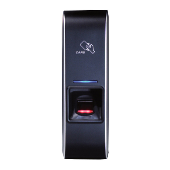
Page 12: Description
Fingerprint sensing part Place a finger on a sensor surface. LED Status per Color Color Mode Description Green constant Authorization Success constant Authorization Fail Pink constant On Processing | V 1.1 | 2010.10 Installation manual Bosch Access Systems GmbH... - Page 13 2 sec. Initialized time due to the internal battery discharge. blue/yellow alternating, 2 sec. DHCP fail blinking, 2 sec. Failed. Please contact to your distributor or Bosch. yellow blinking, 2 sec. Waiting for input. yellow blinking, 1 sec. Receiving IP address from DHCP server.
- Page 14 (TCP/IP) 7 pin connector - digital input and relay output DIP switch: RS485 termination setting - Section 9.3 RS485 Connections Network default setting - Section 10 Network Default Setting | V 1.1 | 2010.10 Installation manual Bosch Access Systems GmbH...
-
Page 15: Product Dimension
BioEntry Plus Product Dimension | en Product Dimension Front Side Metal bracket unit = mm Bosch Access Systems GmbH Installation manual | V 1.1 | 2010.10... -
Page 16: Cables And Connectors
Power and RS485 Pin description Wire Power +12V Power GND black RS485 GND gray RS485 TRx+ blue RS485 TRx- yellow TCP/IP Pin description Wire RJ45 Pin yellow green black | V 1.1 | 2010.10 Installation manual Bosch Access Systems GmbH... - Page 17 Digital Inputs and Relay output Pin description Wire SW1 input yellow SW1 GND black SW2 input green SW2 GND black Relay normal close orange Relay common blue Relay normal open white Bosch Access Systems GmbH Installation manual | V 1.1 | 2010.10...
-
Page 18: Installation Of Wall-Mount Bracket
(1). Step 2: Hook BioEntry Plus on the wall mount bracket. Step 3: Fix BioEntry Plus and wall mounting bracket using a star-shaped screw (2). | V 1.1 | 2010.10 Installation manual Bosch Access Systems GmbH... -
Page 19: Connections
12V ± 10%, at least 500mA. – Comply with standard IEC/EN 60950-1. – To share the power with other devices, use a power supply with higher current ratings. Ethernet Connection Ethernet Connection via HUB Bosch Access Systems GmbH Installation manual | V 1.1 | 2010.10... -
Page 20: Rs485 Connections
Only the devices at the both ends of the bus should be terminated. To enable termination on the RS232-485 converter, refer to the converter’s manual. Disable termination. The stubs should be as short as practical. | V 1.1 | 2010.10 Installation manual Bosch Access Systems GmbH... - Page 21 The stubs should be as short as practical. NOTICE! Maximum number of devices in an RS485 loop is eight (8) including Host PC or Host device. Each device can connect Secure I/Os up to four (4) Bosch Access Systems GmbH Installation manual | V 1.1 | 2010.10...
-
Page 22: Relay Connection
| Connections BioEntry Plus Relay Connection Relay Connection – Fail safe lock Relay Connection – Fail secure lock Relay Connection - Automatic door | V 1.1 | 2010.10 Installation manual Bosch Access Systems GmbH... -
Page 23: Digital Input Connection
BioEntry Plus Connections | en Digital Input Connection Digital Input Connection - RTE, Door sensor Digital Input Connection - Alarm, Emergency sw Wiegand I/O Connection Wiegand Input Wiegand Output Bosch Access Systems GmbH Installation manual | V 1.1 | 2010.10... -
Page 24: Network Default Setting
After recycling BioEntry Plus power, please check the modified TCP/IP or RS-485 setting. NOTICE! Please set the IP address of a PC to 192.168.0.x (except 1) to meet IP bandwidth of the device. | V 1.1 | 2010.10 Installation manual Bosch Access Systems GmbH... -
Page 25: Installation References
BioEntry Plus Installation References | en Installation References Installation Reference 1 - Stand alone Power supply Door lock Exit button Door sensor PC with Bio application via LAN Enroll scanner Bosch Access Systems GmbH Installation manual | V 1.1 | 2010.10... - Page 26 Door lock Exit button Door sensor Wiegand or RS485 secure communication AMC2 4W or 4R4 or Secure I/O Access control system PC with Bio application via LAN Enroll scanner | V 1.1 | 2010.10 Installation manual Bosch Access Systems GmbH...
-
Page 27: Electrical Specification
4.7k resistors internally. Relay Switching capacity (A) 30 V DC 125 V AC Switching power 30 W (resistive) 37.5 VA Switching voltage (V) Bosch Access Systems GmbH Installation manual | V 1.1 | 2010.10... -
Page 28: Troubleshooting
Device doesn’t operate though power is connected. – Check whether a device and a bracket is well connected to each other. If not, a tamper switch is activated and the device doesn’t work. | V 1.1 | 2010.10 Installation manual Bosch Access Systems GmbH... -
Page 29: Device Cleaning
BioStation, wipe off the surface with dry towel. – Note that if the sensor is cleaned by detergent, benzene or thinner, surface is damaged and fingerprint can’t be entered. Bosch Access Systems GmbH Installation manual | V 1.1 | 2010.10... -
Page 30: Fcc Rules
Increase the separation between equipment and receiver. Connect the equipment into an outlet on a circuit difference from that to which the receiver is connected. Consult the dealer or an experienced radio/TV technician for help. | V 1.1 | 2010.10 Installation manual Bosch Access Systems GmbH... -
Page 31: Specifications
50 x 160 x 37 mm Certified KCC, CE, FCC When sharing the power with a device such as electric door lock, enough power is required considering the power requirement for the connected device. Bosch Access Systems GmbH Installation manual | V 1.1 | 2010.10... -
Page 32: Index
| Specifications BioEntry Plus | V 1.1 | 2010.10 Installation manual Bosch Access Systems GmbH... - Page 36 Bosch Access Systems GmbH Charlottenburger Allee 50 D-52068 Aachen Germany www.boschsecurity.com © Bosch Access Systems GmbH, 2010...