Table of Contents

Related Manuals for Panasonic FP0-A21


Summary of Contents for Panasonic FP0-A21
- Page 2 It could lead to an electric shock. Copyright / Trademarks -This manual and its contents are copyrighted. Panasonic -You may not copy this manual, in whole or part, without written consent of Industrial Devices SUNX Co., Ltd.
-
Page 3: Table Of Contents
FP0 A/D Converter Unit Table of Contents Table of Contents Chapter 1 Parts and Terminology Parts and Functions ..........1 −... - Page 4 Expansion Limit and Compatibility FP0 A/D Converter Unit Expansion Limit and Compatibility Expansion limit The unit can be connected to a combined maximum of three other expansion units and intelligent units. Compatibility with the previous FP0 analog unit (FP0−A21) Due to differences in the software design, the programming method is different.
-
Page 5: Parts And Terminology
Chapter 1 Parts and Terminology Parts and Functions ......1 − 3 Analog Input Terminal Block . - Page 6 Parts and Terminology FP0 A/D Converter Unit 1 − 2...
-
Page 7: Parts And Functions
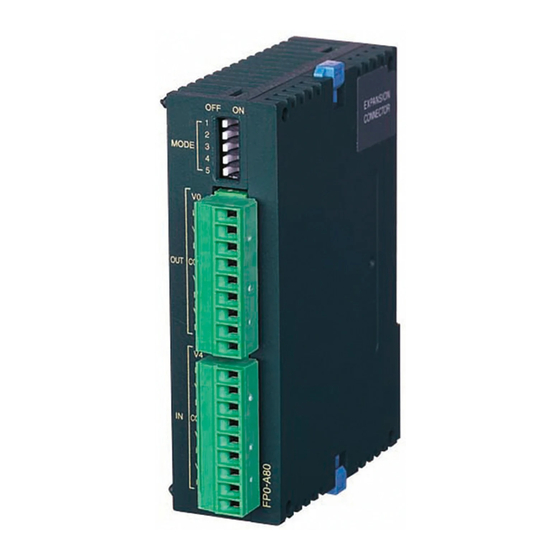
FP0 A/D Converter Unit Parts and Terminology Parts and Functions Parts and Functions FP0−A80 A/D converter unit: AFP0401 Expansion connector Input range setting switch Analog input DIN rail terminal block attachment lever Power supply Expansion hook connector Input range setting switch (voltage/current) This switch is used to change the input mode (between voltage and current). - Page 8 Parts and Terminology FP0 A/D Converter Unit Analog Input Terminal Block Analog Input Terminal Block Pin number Name Description Analog input channel 0, voltage input Analog input channel 0, current input Analog input channel 1, voltage input Analog input channel 1, current input Analog input, input common Analog input channel 2, voltage input Analog input channel 2, current input...
-
Page 9: Connection To Input Devices
Chapter 2 Connection to Input Devices Wiring ......... 2 −... - Page 10 Connection to Input Devices FP0 A/D Converter Unit 2 − 2...
-
Page 11: Wiring
FP0 A/D Converter Unit Connection to Input Devices Wiring Wiring Voltage input Current input Input instrument Input instrument (ch0) (ch0) Input instrument (ch1) Input instrument (ch1) Input instrument Input instrument (ch2) (ch2) Input instrument Input instrument (ch3) (ch3) Input instrument Input instrument (ch4) (ch4) - Page 12 Connection to Input Devices FP0 A/D Converter Unit Wiring 2 − 4...
-
Page 13: Input Range Setting
Chapter 3 Input Range Setting Input Range Setting Switch ..... . . 3 − 3... - Page 14 Input Range Setting FP0 A/D Converter Unit 3 − 2...
- Page 15 FP0 A/D Converter Unit Input Range Setting 3.1 Input Range Setting Switch Input Range Setting Switch Mode Switch Range number Analog 0 to 5V 1 and 2 −10 to 10V −100 to 100mV input 0 to 20mA *1 range range Number Conver- Number...
- Page 16 Input Range Setting FP0 A/D Converter Unit Input Range Setting Switch 3 − 4...
-
Page 17: Chapter 4 A/D Conversion Characteristics
Chapter 4 A/D Conversion Characteristics A/D Conversion Characteristics ....4 − 3... - Page 18 A/D Conversion Characteristics FP0 A/D Converter Unit 4 − 2...
-
Page 19: A/D Conversion Characteristics
FP0 A/D Converter Unit A/D Conversion Characteristics A/D Conversion Characteristics A/D Conversion Characteristics Current range: 0 to 20mA DC input 4000 3000 2000 1000 20(mA) Analog input range Correspondence table of A/D conversion values Input current (mA) A/D conversion value 1000 1500 10.0... - Page 20 A/D Conversion Characteristics FP0 A/D Converter Unit A/D Conversion Characteristics Voltage range: 0 to 5V DC input 4000 3000 2000 1000 5(V) Analog input range Correspondence table of A/D conversion values Input voltage (V) A/D conversion value 1200 1600 2000 2400 2800 3200...
- Page 21 FP0 A/D Converter Unit A/D Conversion Characteristics A/D Conversion Characteristics Voltage range: −10 to +10V DC input 2000 1000 –10 –5 –1000 –2000 Analog input range Correspondence table of A/D conversion values Input voltage (V) A/D conversion value −10.0 −2000 −7.5 −1500 −5.0...
- Page 22 A/D Conversion Characteristics FP0 A/D Converter Unit A/D Conversion Characteristics Voltage range: −100 to +100mV DC input 2000 1000 –100 –50 (mV) –1000 –2000 Analog input range Correspondence table of A/D conversion values Input voltage (mV) A/D conversion value −100.0 −2000 −75.0 −1500...
-
Page 23: Chapter 5 Averaging For Voltage Ranges And Current Ranges
Chapter 5 Averaging for Voltage Ranges and Current Ranges Averaging Function ......5 −... - Page 24 Averaging for Voltage Ranges and Current Ranges FP0 A/D Converter Unit 5 − 2...
-
Page 25: Averaging Function
FP0 A/D Converter Unit Averaging for Voltage Ranges and Current Ranges Averaging Function Averaging Function When the averaging function is set to on, the internal processing of the A/D conversion unit is as shown in the diagram below (in this example there are two input channels, and the input range setting switch Nos. - Page 26 Averaging for Voltage Ranges and Current Ranges FP0 A/D Converter Unit Averaging Function 5 − 4...
-
Page 27: I/O Allocation And Program
Chapter 6 I/O Allocation and Program 6 .1 I/O Number of A/D Converter Unit ....6 − 3 6 .2 Program of A/D Converter Unit . - Page 28 I/O Allocation and Program FP0 A/D Converter Unit 6 − 2...
- Page 29 FP0 A/D Converter Unit I/O Allocation and Program I/O Number of A/D Converter Unit I/O Number of A/D Converter Unit I/O number of A/D converter unit Second Third First expansion expansion expansion A combined maximum of three A/D converter FP0 Control unit units and other expansion units can be con- nected to one control unit.
- Page 30 I/O Allocation and Program FP0 A/D Converter Unit I/O Number of A/D Converter Unit About the conversion data switch flags The resolution of the A/D converter unit is 12 bits, but when data is transferred to the control unit, it is converted to 16−bit data. Therefore, although the WX2 data requires no processing, for the WX3 data, the top two bits are used as conversion data switching flags.
-
Page 31: Program Of A/D Converter Unit
FP0 A/D Converter Unit I/O Allocation and Program Program of A/D Converter Unit Program of A/D Converter Unit Ladder program example for loading data from each channel Indicates the program that stores in data registers DT0 to DT7 the from ch0 to ch7 A/D conversion data that is assigned to the first expansion. - Page 32 I/O Allocation and Program FP0 A/D Converter Unit Program of A/D Converter Unit 6 − 6...
-
Page 33: Chapter 7 Specifications
Chapter 7 Specifications Specifications ........7 − 3 Dimensions . - Page 34 Specifications FP0 A/D Converter Unit 7 − 2...
-
Page 35: Specifications
FP0 A/D Converter Unit Specifications Specifications Specifications General specifications Item Description Rated operation voltage 24V DC Operating voltage range 21.6 to 26.4V DC Rated current consumption 60mA or less (at 24V DC) ∗ Current consumption increase of control unit 20mA or less (at 24V DC) Allowable instantaneous stop time 10ms Ambient temperature... - Page 36 Specifications FP0 A/D Converter Unit Specifications Analog input specifications Item Description 8 channels/unit (the number of input points can be switched to 2, 4, 6 or Number of input points 8 channels) Voltage range 0 to 5 V, −10 to +10 V, −100 to +100 mV Input range Input range Current range...
- Page 37 FP0 A/D Converter Unit Specifications Specifications • ∗ 3) Setting value switch for the number of input channels • ∗ 4) The control unit loads two channels’ worth of data at each control unit scan. In other words, if the switch for the number of input channels is set to eight channels, the control unit data is updated once every four scans.
-
Page 38: Dimensions
Specifications FP0 A/D Converter Unit Dimensions Dimensions 25.0/0.984 10.0/0.394 60.0/2.362 3.5/0.138 (unit: mm/in.) 7 − 6... -
Page 39: Record Of Changes
Record of changes Manual No. Date Description of changes ARCT1F321E/ NOV.2000 First edition ACG-M321E ARCT1F321E-1/ FEB.2006 Second edition ACG-M321E-1 ARCT1F321E-2/ NOV.2008 Third edition ACG-M321E-2 - Change in Corporate name ARCT1F321E-3 AUG.2011 Fourth edition - Change in Corporate name ARCT1F321E-4 SEP.2012 Fifth edition... - Page 40 Record of changes FP0 A/D Converter Unit R - 2...