Quick Links
See also:
User Manual
Set Service
Set Service parameters are listed in the table below, along with a description of the options that are possible.
'SET SERVICE'
Parameter
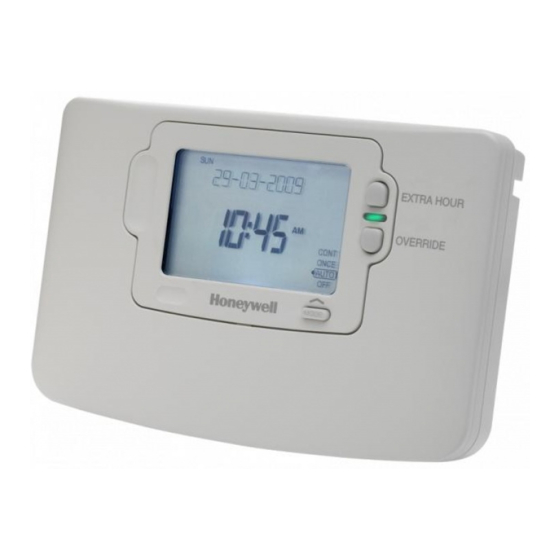
LoT™ Display
Default Value
Range of
PARAMETER
ID
Description
Values
Enable or disable service
AL
SERV MODE
0
0, 1
alarm feature
Number of days till next
d
SERV DAYS
364
001 to 400
Service
Number of days for advance
Ad
DAYS NOTICE
28
0 to 28
warning
Action taken at time-out
to
ACTION TYPE
2
0, 1, 2
Number of EXTRA HOUR
bP
1HR BOOSTS
uL
uL, 1 to 99
button presses allowed in
'Prompt' mode
Enable telephone call
tC
SHOW PHONE
0
0, 1
number display
Enter telephone STD code
St
STD CODE
-------
1
Enter telephone number
nU
NUMBER
---------
1
* Reset 'SET SERVICE'
rS
ALRM RESET
1
0,1
parameters to default values
* This parameter by default has a value of 1, unless any other parameter is adjusted, when it will change to 0. Set it to 1 to reset all parameters back to defaults
To Enter Set Service Mode:
a. Enter Installer Modes (as described on Page 3) and
navigate to SET SERVICE mode. In response to the
query 'SET SERVICE OK ?' press the
button to enter
SET SERVICE.
b. The message 'ENTER PIN' will now be displayed,
along with the 4-digit entry code format 0---. The first
digit will be flashing, to indicate it can be changed.
Use the
or
buttons to set the first digit, and
press
to confirm the digit.
c. At this point the first digit will stop flashing and the
second digit will begin to flash, indicating it can be
changed.
d. Proceed in this way to enter the 4 digits of the PIN code.
Upon confirming the last digit, if the PIN was incorrect,
the message 'INVALID' will be displayed, and then the
whole process will start again from step b. above.
e. If the PIN was correct, the first SET SERVICE parameter
or
AL will be available to change. This allows you to
enable or disable all the service alarm features. At
every step, the LoT™ Display will inform you what the
parameter means and what option you have selected.
The parameter ID is usually shown on the display
separated by a colon from the parameter value.
f.
You can change the parameter value by pressing the
or
buttons. At this point the description in the
LoT™ Display will change and the parameter value
will flash. If you press
the value will stop flashing
and will be saved for use.
g. Press
to move to the next parameter available for
editing. The parameter ID will change accordingly.
h. Keep pressing
to step around the list of parameters,
and use
or
buttons to change the parameter
value.
i.
Any parameter changes that have been confirmed
with the
button will be saved and used. Some
parameters may be made invalid by a previous
parameter setting, and these will be skipped over in
the setting process.
5
Change PIN
If you intend to change the PIN code, please ensure you take a note of
the new code that you are setting.
Description [LoT™ Display Description]
The process for changing the current PIN code is as follows:
a. Enter Installer Modes (as described on Page 3) and navigate to
0 = disabled
[DISABLED]
CHANGE PIN mode. In response to the query 'CHANGE PIN OK ?'
1 = enabled
[ENABLED]
press the
button to enter CHANGE PIN mode.
001....400
[SET DAY COUNT]
b. The message 'ENTER PIN' will now be displayed, along with the
000 = service is overdue
4-digit entry code format 0---. The first digit will be flashing, to
indicate it can be changed. Use the
0 ...28
[SET DAYS NOTICE]
digit, and press
to confirm the digit.
c. At this point the first digit will stop flashing and the second digit will
0 = no action,
[NO ACTION]
proceed to flash, indicating it can be changed.
1 = switch off,
[SWITCH OFF]
2 = 'prompt' mode
[PROMPT MODE]
d. Proceed in this way to enter the 4 digits of the old PIN code. Upon
confirming the last digit, if the PIN was incorrect, the message
uL = unlimited number,
[NUM BOOSTS]
'INVALID' will be displayed, and then the whole process will start
1...99 = specified number
again from step b. above.
of button presses, after
which unit switches off
e. If the PIN was correct the message 'SET NEW PIN OK ?' will appear.
As before, use the
0 = disabled
[DISABLED]
button to confirm. Upon confirming the final digit, the message 'PIN
1 = enabled
[ENABLED]
SET' will be displayed, and the new PIN code will be held on the
When a
or
button is first pressed the
screen for 5 seconds, to give you time to note it down.
LoT™ Display shows a row of dashes which can
f.
After setting the new PIN code, you will be taken back to the SETUP
be adjusted using
or
buttons, then verified
MENU.
using the
button.
When a
or
button is first pressed the
LoT™ Display shows a row of dashes which can
What the User will See When a Service is Due
be adjusted using
or
buttons, then verified
If the advance warning has been configured,
using the
button.
the screen will flash this message every few
0 = do not reset
[NO RESET]
seconds, and the User should telephone to
1 = default parameters
[RESET]
arrange a service call before the final date
when the service is due.
When the boiler service is overdue the screen
will keep flashing the words "SERVICE DUE"
every second.
If the NO ACTION option has been selected,
the unit will continue to operate as normal
and the real time will continue to be shown.
If the SWITCH OFF or PROMPT Actions
have been selected, the 'SERVICE DUE'
message will flash and the word "OFF" will
appear on the display. The boiler has been
switched off to ensure the safety of the User.
A service appointment should be arranged
immediately.
In PROMPT operation, the User can obtain
limited use of the boiler by pressing the
or
EXTRA HOUR button. Each button press
will allow operation of the boiler for 1 hour at a
time, and the screen will display the message
"On1h", as shown. A service appointment
should be arranged immediately.
If a contact telephone number has been
programmed into the ST9100S, a message will appear on the LoT™
Display indicating the number that should be called.
Honeywell Control Systems Ltd.
Arlington Business Park,
Bracknell
Berkshire
RG12 1EB
Technical Help Desk: 08457 678999
www.honeywelluk.com
Completion Checklist for Installation
1. Check unit powers up correctly, and that the display does not remain
blank.
2. Set operating mode to AUTO and switch on and off using the
OVERRIDE button, to ensure the system is operating correctly.
3. Check the factory-set day, date, and time are correct and adjust if
necessary. Refer to User Guide for details.
4. If required, enter Installer Setup Mode and adjust Installer Parameters
to match the lifestyle and needs of the User. Remember to make a
note of these parameter changes in the Configuration Data section
or
buttons to set the first
of the User Guide.
5. If required, enter Set Service Mode and enable the Boiler Service
Reminder, and set the appropriate Service parameters.
6. Explain the operation of the product to the User and help them to set
their programme. There are 3 built-in profiles that can be used as a
basis for typical User programmes.
7. Explain when the User should contact someone to arrange a Service
Visit, and what you have programmed to happen when the Service is
overdue.
or
buttons to set the digits, and the
8. If required, attach the self-adhesive programme guide label to the
underside of the cover flap. The label is supplied in the box and
requires to be peeled away from the backing material before use.
9. Write the date of installation, your name and telephone number in the
space provided in the User Guide, in the section 'Boiler & System
Service Log'.
10. Remember to leave the User Guide and Installation Instructions with
the User and remind them to keep them in a safe place. This forms
part of a Home Information Pack.
Resetting the Service Timer Function
If the Service Timer function is enabled you will be required to reset it
after the boiler service has been carried out.
The process for resetting the Service Timer is as follows:
a. Enter Installer Modes (as described on page 3) and navigate to
SET SERVICE mode. In response to the query 'SET SERVICE OK ?'
press the
button to enter SET SERVICE mode.
b. If you no longer require the Service Timer, disable it by setting
parameter AL to 0 and confirm with the
button.
c. If you still require the Service Timer, set the number of days until
the next service is due using parameter d and confirm with the
button.
d. Whilst in SET SERVICE mode, use the opportunity to change any
other service parameters if required.
e. Exit by moving the slider to the next position and back again to
RUN.
This product and its associated documentation and packaging are protected
by various intellectual property rights belonging to Honeywell Inc and its
subsidiaries and existing under the laws of the UK and other countries. These
intellectual and property rights may include patent applications, registered
designs, unregistered designs, registered trade marks, unregistered trade
marks and copyrights.
Honeywell reserves the right to modify this document, product and functionality
without notice. This document replaces any previously issued instructions and
is only applicable to the product(s) described.
This product has been designed for applications as described within this
document. For use outside of the scope as described herein, refer to Honeywell
for guidance. Honeywell cannot be held responsible for misapplication of the
product(s) described within this document.
Manufactured for and on behalf of the Environment and Combustion Controls
Division of Honeywell Technologies Sarl, Ecublens, Route du Bois 37,
Switzerland by its Authorised Representative Honeywell Inc.
50022736-003 A
© 2007 Honeywell International Inc.
6
ST9100S Timer
With Boiler Service Reminder / Shut-down Feature
INSTALLATION INSTRUCTIONS
Introduction
Specification
ST9100S is an Electronic Timer which provides accurate time control
Power Supply: 230V~, 50...60Hz, 10W
for central heating systems and other applications. It has an in-built
Switch Action: 1 x Potential Free SPST, 1x 230Vac SPST
Boiler Service Reminder / Shut-down Feature developed to assist Social
Housing Landlords to comply with the requirements of Regulation 36 of
Switch Rating:
230V~, 50...60Hz, 3(3)A max for both relays
the Gas Safety (Installation & Use) Regulations 1998. This is intended as
potential free relay rated 10mA at 12Vdc min
an aid to compliance but should not be used to replace the Landlord's
Factory set clock
existing Servicing procedures.
ST9100S is suitable for replacing a wide range of Timers on the market,
Power Reserve: lifetime battery
and is a direct replacement for Honeywell ST6100S Timers without the
Programmes/Settings: permanently stored in NV RAM
need for re-wiring.
Approvals: Conforms to protection requirements of
ST9100S Timers can be combined with other Honeywell controls such as
Directives 2006/95EC and 89/336EC
Room Thermostats, Cylinder Thermostats, Wiring Centres and Zone or
Diverting Valves to form a fully automatic central heating control system.
Mounting
Mounting Options
If the ST9100S is replacing an existing ST6100S then the existing wall-plate
and wiring may be used, subject to any required electrical checks.
The Timer should be mounted at a level where the display can be seen
clearly, (1.2 to1.5m from the floor) and the ambient temperature is within
the range of 0 to 40°C. The ST9100S is for use in normal domestic
environments.
CAUTION
Isolate power supply and make safe before wiring the unit to prevent
electric shock and equipment damage. Installation should be carried
out by a qualified electrician or competent heating engineer.
To remove the unit from the wall-plate, slacken the two securing screws
at the bottom of the ST9100S and hinge the unit up to separate the two
Ensure the mounting surface is supporting and fully covers the wiring
halves.
wall-plate.
Wiring
ALL WIRING MUST BE IN ACCORDANCE WITH I.E.E. REGULATIONS.
THIS UNIT IS FOR FIXED WIRING ONLY.
A switch, having contact separation of at least 3mm in all poles (formerly
Class 'A'), must be incorporated in the fixed wiring as a means of
disconnecting the supply.
The unit is a Class II (double insulated) device. A parking terminal is
provided for external earth continuity.
The system must be appropriately fused. A fuse rated at no more than
3 Amps should be installed.
The unit has 4 knockouts for surface wiring, care must be taken to ensure
that the cable or mini-trunking completely fills the knockout hole without
leaving any gaps.
Final Assembly
Clip the unit onto the hinges on the top of the wallplate and hinge down
into position. Tighten the two securing screws using a screwdriver.
Switch on the power – the unit will now be operating according to the
built-in programme. Note : the ST9100S is supplied with a factory set
clock for faster installation.
Refer to ST9100S User Guide for programming details.
1
RECOMMENDED CLEARANCE DISTANCES:
ABOVE WALLPLATE:
110mm
BELOW WALLPLATE:
100mm
LEFT/RIGHT OF WALLPLATE:
10mm
a. Surface mounting
concealed wiring
b. Flush switchbox
Fixing holes are
spaced to suit BS4662
requirements
c. Surface mounting with
surface wiring in
mini trunking

Related Manuals for Honeywell ST9100S


Summary of Contents for Honeywell ST9100S
- Page 1 Upon confirming the last digit, if the PIN was incorrect, at the bottom of the ST9100S and hinge the unit up to separate the two Ensure the mounting surface is supporting and fully covers the wiring EXTRA HOUR button.
- Page 2 2. The ST9100S is a single channel timer designed for combi-boiler Note: If ST6100S terminals 2 and 3 do not have wires connected to them, there is no need to connect wires to ST9100S terminals 2 and 3. INSTALLER PARAMETER Parameter LoT™...