
Related Manuals for Mitsubishi Electric FR-CS84-012


Summary of Contents for Mitsubishi Electric FR-CS84-012
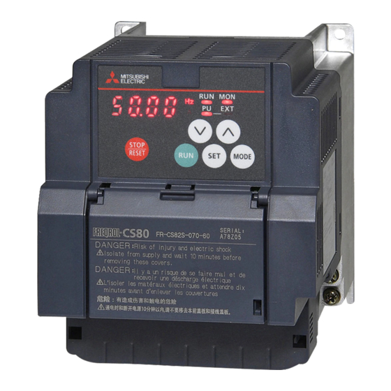
- Page 1 INVERTER FREQROL-CS80 INSTRUCTION MANUAL (DETAILED) FR-CS84-012 to 295 FR-CS82S-025 to 100...
-
Page 2: Table Of Contents
Safety instructions..............6 Chapter 1 INTRODUCTION . - Page 3 3.1.1 Leakage currents and countermeasures............. . . 48 3.1.2 Countermeasures against inverter-generated EMI .
- Page 4 5.4.4 Starting frequency ................99 (D) Operation command and frequency command .
- Page 5 5.12.7 Regeneration avoidance function ..............199 5.12.8 Increased magnetic excitation deceleration .
- Page 6 Chapter 8 SPECIFICATIONS ......238 Inverter rating............. 238 Common specifications .
-
Page 7: Safety Instructions
• A person who possesses a certification in regard with electric appliance handling, or person took a proper engineering training. Such training may be available at your local Mitsubishi Electric office. Contact your local sales office for schedules and locations. -
Page 8: Fire Prevention
Electric shock prevention WARNING Do not remove the front cover or the wiring cover while the inverter power is ON, and do not run the inverter with the front cover or the wiring cover removed as the exposed high voltage terminals or the charging part of the circuitry can be touched. - Page 9 Additional instructions The following instructions must be also followed. If the product is handled incorrectly, it may cause unexpected fault, an injury, or an electric shock. CAUTION Transportation and installing Any person who is opening a package using a sharp object, such as a knife or cutter, must wear gloves to prevent injuries caused by the edge of the sharp object.
- Page 10 WARNING Usage Any person must stay away from the motor or machinery when the retry function or the automatic restart after instantaneous power failure function is set in the inverter as the motor or the machine will restart suddenly after an inverter fault or instantaneous power failure.
- Page 11 General instruction For clarity purpose, illustrations in this Instruction Manual may be drawn with covers or safety guards removed. Ensure all covers and safety guards are properly installed prior to starting operation.
-
Page 12: Chapter 1 Introduction
INTRODUCTION CHAPTER 1 Product checking and accessories .........................13 Component names ..............................14 About the related manuals............................14... - Page 13 Operation panel on the inverter / enclosure surface operation panel (FR-PA07) / LCD operation panel (FR- LU08) / parameter unit Inverter Mitsubishi Electric FREQROL-CS80 series inverter Parameter number (Number assigned to function) PU operation Operation using the PU (operation panel/parameter unit)
-
Page 14: Product Checking And Accessories
Product checking and accessories Unpack the product and check the rating plate and the capacity plate of the inverter to ensure that the model agrees with the order and the product is intact. Inverter model CS 8 4 Symbol Voltage class Symbol Voltage Symbol... -
Page 15: Component Names
Component names Component names are as follows. Refer to Symbol Name Description page Operation panel Operates and monitors the inverter. Control circuit terminal block Connects cables for the control circuit. Main circuit terminal block Connects cables for the main circuit. Connects the operation panel or the parameter unit. - Page 16 INSTALLATION AND CHAPTER 2 WIRING Peripheral devices ..............................16 Removal and reinstallation of the wiring cover .......................20 Installation of the inverter and enclosure design ....................23 Terminal connection diagrams..........................29 Main circuit terminals ..............................31 Control circuit................................35 Communication connectors and terminals......................41 Connection of stand-alone option units ........................42...
-
Page 17: Chapter 2 Installation And Wiring
INSTALLATION AND WIRING This chapter explains the installation and the wiring of this product. Always read the instructions before use. Peripheral devices 2.1.1 Inverter and peripheral devices (b) AC power supply Enclosure surface LCD operation operation panel (FR-LU08) panel (FR-PA07) RS-232C - RS-485 converter is (c) Moulded case circuit breaker By connecting the connection... - Page 18 Symb Name Overview Refer to page The life of the inverter is influenced by the surrounding air temperature. The surrounding air temperature should be as low as possible within the permissible range. This must be noted especially when the inverter is Inverter (FREQROL-CS80) installed in an enclosure.
-
Page 19: Peripheral Devices
• This is a matrix showing the rated current of the molded case circuit breaker (MCCB) or earth leakage circuit breaker (ELB) (NF or NV type) according to the selected inverter and rating. Without the power factor With the power factor Voltage Inverter model improving reactor improving reactor FR-CS84-012 FR-CS84-022 FR-CS84-036 10 A 10 A Three- FR-CS84-050 15 A... - Page 20 • This is a matrix showing the model name of the Mitsubishi magnetic contactor to be installed at the inverter's input line according to the selected inverter and rating. Without the power factor With the power factor Voltage Inverter model improving reactor improving reactor FR-CS84-012 S-T10 S-T10 FR-CS84-022 S-T10 S-T10 FR-CS84-036 S-T10...
-
Page 21: Removal And Reinstallation Of The Wiring Cover
Removal for the FR-CS84-160 or lower and the FR-CS82S inverters To remove the wiring cover, loosen the mounting screw of the cover, and pull out the cover. For the FR-CS84-012 to 080 or the FR-CS82S inverter, open the front cover to remove the wiring cover. - Page 22 Reinstallation for the FR-CS84-160 or lower and the FR-CS82S inverters To reinstall the wiring cover, fit the cover to the inverter along the guides. Fasten the cover with the mounting screw. FR-CS84-012 and 022 FR-CS84-036 to 080 FR-CS82S-025, 042...
- Page 23 Removal for the FR-CS84-230 or higher inverters To remove the wiring cover, loosen the mounting screw of the cover. While holding the hooks of the inverter, pull out and remove the cover. FR-CS84-230 and 295 Wiring cover Hook Reinstallation for the FR-CS84-230 or lower and the FR-CS82S inverters Fit the two sockets on the bottom of the cover to the hooks on the inverter, and install the cover to the inverter.
-
Page 24: Installation Of The Inverter And Enclosure Design
Installation of the inverter and enclosure design When designing or manufacturing an inverter enclosure, determine the structure, size, and device layout of the enclosure by fully considering the conditions such as heat generation of the contained devices and the operating environment. An inverter unit uses many semiconductor devices. - Page 25 Humidity Operate the inverter within the ambient air humidity of usually up to 95% with circuit board coating. Too high humidity will pose problems of reduced insulation and metal corrosion. On the other hand, too low humidity may cause a spatial electrical breakdown.
-
Page 26: Amount Of Heat Generated By The Inverter
When the heatsink is installed inside the enclosure, the amount of heat generated by the inverter unit is shown in the following tables. Amount of heat Voltage Inverter model generated (W) FR-CS84-012 FR-CS84-022 FR-CS84-036 FR-CS84-050 Three-phase FR-CS84-080 400 V class... -
Page 27: Cooling System Types For Inverter Enclosure
2.3.3 Cooling system types for inverter enclosure From the enclosure that contains the inverter, the heat of the inverter and other equipment (transformers, lamps, resistors, etc.) and the incoming heat such as direct sunlight must be dissipated to keep the in-enclosure temperature lower than the permissible temperatures of the in-enclosure equipment including the inverter. -
Page 28: Inverter Installation
2.3.4 Inverter installation Inverter placement FR-CS84-012, 022 FR-CS84-036 to 080 FR-CS82S-025, 042 FR-CS82S-070, 100 FR-CS84-120, 160 FR-CS84-230, 295 • Install the inverter on a strong surface securely with screws. • Leave enough clearances and take cooling measures. • Avoid places where the inverter is subjected to direct sunlight, high temperature and high humidity. - Page 29 Installation orientation of the inverter Install the inverter on a wall as specified. Do not mount it horizontally or in any other way. Above the inverter Heat is blown up from inside the inverter by the small fan built in the unit. Any equipment placed above the inverter should be heat resistant.
-
Page 30: Terminal Connection Diagrams
Terminal connection diagrams Source logic Main circuit terminal Control circuit terminal Single-phase power input Brake unit MCCB (Option) Single-phase R/L1 AC power S/L2 supply MCCB Motor R/L1 Inrush current S/L2 limit circuit Three-phase T/L3 AC power supply Earth (Ground) Main circuit Earth (Ground) Control circuit Relay output... - Page 31 The signal assigned to each of these terminals can be changed to the reset signal, etc. using the input terminal assignment function (Pr.178 to Pr.182). (Refer to page 142). To use terminals PC and SD for a 24 VDC power supply, check the wiring for an incorrect short of these terminals. Terminal input specifications can be changed by analog input specification switchover (Pr.73, Pr.267).
-
Page 32: Main Circuit Terminals
For earthing (grounding) the inverter chassis. Be sure to earth (ground) Earth (ground) the inverter. 2.5.2 Terminal layout of the main circuit terminals, wiring of power supply and the motor FR-CS84-012 and 022 FR-CS84-036 to 080 FR-CS82S-025, 042 FR-CS82S-070, 100 R/L1 S/L2 T/L3 R/L1 S/L2 T/L3... -
Page 33: Applicable Cables And Wiring Length
2.5.3 Applicable cables and wiring length Select a recommended cable size to ensure that the voltage drop will be 2% or less. If the wiring distance is long between the inverter and motor, the voltage drop in the main circuit will cause the motor torque to decrease especially at a low speed. -
Page 34: Earthing (Grounding) Precautions
Total wiring length (example of 400 V class inverter of the FR-CS84-120 or higher) 100 m 50 m 100 m or less 100 m + 50 m = 150 m When driving a 400 V class motor by the inverter, surge voltages attributable to the wiring constants may occur at the motor terminals, deteriorating the insulation of the motor. - Page 35 • Whenever possible, use the independent earthing (grounding) for the inverter. If independent earthing (grounding) (I) is not available, use (II) common earthing (grounding) in the following figure where the inverter is connected with the other equipment at an earthing (grounding) point. Do not use the other equipment's earthing (grounding) cable to earth (ground) the inverter as shown in (III).
-
Page 36: Control Circuit
Control circuit 2.6.1 Details on the control circuit terminals Input signal Refer Terminal Type Terminal name Terminal function description Rated specification symbol page Turn ON the STF signal to start When the STF and Forward rotation start forward rotation and turn it OFF to STR signals are Input resistance: 4.7 kΩ, stop. -
Page 37: Control Logic (Sink/Source) Change
Output signal Terminal Refer to Type Terminal name Terminal function description Rated specification symbol page 1 changeover contact output that indicates that an inverter's protective function has been activated and the outputs are Contact capacity: 30 VAC Relay output stopped. - Page 38 Sink logic and source logic • In the sink logic, a signal turns ON when a current exits from the corresponding signal input terminal. Terminal SD is common to the contact input signals. • In the source logic, a signal turns ON when a current enters into the corresponding signal input terminal. Terminal PC is common to the contact input signals.
-
Page 39: Wiring Of Control Circuit
2.6.3 Wiring of control circuit Control circuit terminal layout • Recommended cable gauge: 0.3 to 0.75 mm RL RM RH SD PC STF STR Wiring method Power supply connection For the control circuit wiring, strip off the sheath of a cable, and use it with a blade terminal. For a single wire, strip off the sheath of the wire and apply directly. - Page 40 • NICHIFU Co., Ltd. Blade terminal Insulation cap product Crimping tool product Cable gauge (mm product number number number 0.3 to 0.75 BT 0.75-11 VC 0.75 NH 69 Insert the wires into a socket. When using a single wire or stranded wires without a blade terminal, push the open/close button all the way down with a flathead screwdriver, and insert the wire.
-
Page 41: Wiring Precautions
• Terminal 5 is a common terminal for the frequency setting signal input (via terminal 2 or 4). It should be protected from external noise using a shielded or twisted cable. Signal inputs by contactless switches The contact input terminals of the inverter (STF, STR, RH, RM, RL) can be controlled using a transistor instead of a contact switch as shown below. -
Page 42: Communication Connectors And Terminals
Communication connectors and terminals 2.7.1 PU connector Mounting the operation panel or the parameter unit on the enclosure surface • Having an operation panel or a parameter unit on the enclosure surface is convenient. With a connection cable, the operation panel or the parameter unit can be mounted to the enclosure surface and connected to the inverter. -
Page 43: Connection Of Stand-Alone Option Units
Connection of stand-alone option units The inverter accepts a variety of stand-alone option units as required. Incorrect connection will cause inverter damage or accident. Connect and operate the option unit carefully in accordance with the Instruction Manual of the corresponding option unit. 2.8.1 Connection of the brake unit (FR-BU2) Connect the brake unit (FR-BU2(H)) as follows to improve the braking capability during deceleration. - Page 44 Connection example with the FR-BR-(H) resistor unit FR-BR MCCB Motor R/L1 Three-phase AC S/L2 power supply T/L3 FR-BU2 Inverter 10 m or less When wiring, make sure to match the terminal symbol (P/+, N/-) at the inverter side and at the brake unit (FR-BU2) side. (Incorrect connection will damage the inverter and brake unit.) When the power supply is 400 V class, install a stepdown transformer.
-
Page 45: Connection Of The High Power Factor Converter (Fr-Hc2)
2.8.2 Connection of the high power factor converter (FR- HC2) When connecting the high power factor converter (FR-HC2) to suppress power harmonics, perform wiring securely as follows. Incorrect connection will damage the high power factor converter and the inverter. High power Outside box factor converter Reactor1... -
Page 46: Connection Of The Power Regeneration Common Converter (Fr-Cv)
2.8.3 Connection of the power regeneration common converter (FR-CV) When wiring for connecting the power regeneration common converter (FR-CV) to the inverter, make sure to match the terminal symbols (P/+, N/-) on the inverter and on the power regeneration common converter. R/L1 S/L2 T/L3... - Page 47 MEMO 2. INSTALLATION AND WIRING 2.8 Connection of stand-alone option units...
- Page 48 PRECAUTIONS FOR USE CHAPTER 3 OF THE INVERTER Electro-magnetic interference (EMI) and leakage currents ..................48 Power supply harmonics............................53 Installation of a reactor ............................57 Power shutdown and magnetic contactor (MC)......................58 Countermeasures against deterioration of the 400 V class motor insulation............59 Checklist before starting operation .........................60 Failsafe system which uses the inverter .........................62...
-
Page 49: Chapter 3 Precautions For Use Of The Inverter
PRECAUTIONS FOR USE OF THE INVERTER This chapter explains the precautions for use of this product. Always read the instructions before use. Electro-magnetic interference (EMI) and leakage currents 3.1.1 Leakage currents and countermeasures Capacitances exist between the inverter I/O cables, other cables and earth and in the motor, through which a leakage current flows. - Page 50 MCCB Thermal relay Motor Power Inverter supply Line-to-line static capacitances Line-to-line leakage currents path Countermeasure • Use Pr.9 Electronic thermal O/L relay. • If the carrier frequency setting is high, decrease the Pr.72 PWM frequency selection setting. Note that motor noise increases. Selecting Pr.240 Soft-PWM operation selection makes the sound inoffensive. To ensure that the motor is protected against line-to-line leakage currents, it is recommended to use a temperature sensor to directly detect motor temperature.
-
Page 51: Countermeasures Against Inverter-Generated Emi
NOTE • Install the earth leakage circuit breaker (ELB) on the input side of the inverter. • In the connection earthed-neutral system, the sensitivity current is blunt against a ground fault in the inverter output side. Earthing (grounding) must conform to the requirements of national and local safety regulations and electrical codes. (NEC section 250, IEC 61140 class 1 and other applicable standards) •... - Page 52 Techniques to reduce electromagnetic noises that are radiated by the inverter to cause the peripheral devices to malfunction (EMI countermeasures) Inverter-generated noises are largely classified into those radiated by the cables connected to the inverter and inverter main circuits (I/O), those electromagnetically and electrostatically induced to the signal cables of the peripheral devices close to the main circuit power supply, and those transmitted through the power supply cables.
- Page 53 Data line filter Data line filter is effective as an EMI countermeasure. Provide a data line filter for the detector cable, etc. • Commercially available data line filter: ZCAT3035-1330 (by TDK), ESD-SR-250 (by NEC TOKIN) • Specification example (ZCAT3035-1330 by TDK) Item Description 10 to 100 MHz...
-
Page 54: Power Supply Harmonics
Power supply harmonics 3.2.1 Power supply harmonics The inverter may generate power supply harmonics from its converter circuit to affect the power generator, power factor correction capacitor etc. Power supply harmonics are different from noise and leakage currents in source, frequency band and transmission path. - Page 55 • "Specific Consumer Guidelines" This guideline sets forth the maximum harmonic currents outgoing from a high-voltage or especially high-voltage receiving consumer who will install, add or renew harmonic generating equipment. If any of the maximum values is exceeded, this guideline requires that consumer to take certain suppression measures. •...
- Page 56 Reactor 11th 13th 17th 19th 23rd 25th Not used Used (AC side) 14.5 Three-phase bridge (capacitor smoothing) Used (DC side) Used (AC, DC sides) Single-phase bridge Not used ― ― (capacitor smoothing, double voltage Used (AC side) ― ― rectification) Single-phase bridge Not used 33.5...
- Page 57 Calculation of equivalent capacity P0 of harmonic generating equipment "Equivalent capacity" is the capacity of a 6-pulse converter converted from the capacity of consumer's harmonic generating equipment and is calculated by the following equation. If the sum of equivalent capacities is higher than the limit (refer to the list of the equivalent capacity limits), harmonics must be calculated by the equation in next subheading.
-
Page 58: Installation Of A Reactor
Installation of a reactor When the inverter is connected near a large-capacity power transformer (500 kVA or more) or when a power factor correction capacitor is to be switched over, an excessive peak current may flow in the power input circuit, damaging the converter circuit. To prevent this, always install an AC reactor (FR-HAL), which is available as an option. -
Page 59: Power Shutdown And Magnetic Contactor (Mc)
Power shutdown and magnetic contactor (MC) Inverter input side magnetic contactor (MC) On the inverter input side, it is recommended to provide an MC for the following purposes. (Refer to page 18 for selection.) • To disconnect the inverter from the power supply at activation of a protective function or at malfunctioning of the driving system (emergency stop, etc.). -
Page 60: Countermeasures Against Deterioration Of The 400 V Class Motor Insulation
Countermeasures against deterioration of the 400 V class motor insulation In the PWM type inverter, a surge voltage attributable to wiring constants is generated at the motor terminals. Especially in a 400 V class motor, the surge voltage may deteriorate the insulation. When the 400 V class motor is driven by the inverter, consider the following countermeasures: ... -
Page 61: Checklist Before Starting Operation
Checklist before starting operation The FREQROL-CS80 series inverter is a highly reliable product, but incorrect peripheral circuit making or operation/handling method may shorten the product life or damage the product. Before starting operation, always recheck the following points. Refer to Check by Checkpoint Countermeasure... - Page 62 (This is motor bearing. effective regardless of the use of the capacitive filter.) Mitsubishi Electric capacitive filter: FR-BIF, SF[], FR-E5NF-[], FR- S5NFSA[] Recommended common mode choke: FT-3KM F series FINEMET® common mode choke cores manufactured by Hitachi Metals, Ltd.
-
Page 63: Failsafe System Which Uses The Inverter
Failsafe system which uses the inverter When a fault is detected by the protective function, a fault signal is output. However, a fault signal may not be output at an inverter's fault occurrence when the detection circuit or output circuit fails, etc. Although Mitsubishi assures the best quality products, provide an interlock which uses inverter status output signals to prevent accidents such as damage to the machine when the inverter fails for some reason. - Page 64 Checking the inverter operating status by the start signal input to the inverter and by the Inverter running signal output from the inverter ... (c) The Inverter running (RUN) signal is output when the inverter is running. Check if the RUN signal is output while a start signal (the STF/STR signal for forward/reverse rotation command) is input to the inverter.
- Page 65 Command speed and actual operation check Check for a gap between the actual speed and commanded speed by comparing the inverter's speed command and the speed detected by the speed detector. Controller System failure Sensor Inverter (speed, temperature, air volume, etc.) To the alarm detection sensor 3.
- Page 66 BASIC OPERATION CHAPTER 4 Operation panel ..............................66 Monitoring the inverter ............................70...
-
Page 67: Chapter 4 Basic Operation
BASIC OPERATION This chapter explains the basic operation of this product. Always read the instructions before use. Operation panel 4.1.1 Components of the operation panel Appearance Name Description PU: ON when the inverter runs in the PU operation mode. EXT: ON when the inverter runs in the External operation mode. (ON when the inverter Inverter operation in the initial setting is powered ON.) mode LED indicator... -
Page 68: Basic Operation Of The Operation Panel
4.1.2 Basic operation of the operation panel Basic operation Output frequency monitor Output current monitor Output voltage monitor (At power-ON) (Example) (Example) (Example) Blinking Blinking Blinking Faults history Faults history 1 Faults history 2 Faults history 8 External operation mode (At power-ON ) PU operation mode PU Jog operation mode Pressing the... -
Page 69: Digital Characters And Their Corresponding Printed Equivalents
Parameter setting mode In the parameter setting mode, inverter functions (parameters) are set. The following table explains the indications in the parameter setting mode. Operation panel Refer to Function name Description indication page Under this mode, the set value of the displayed parameter number is read Parameter setting mode or changed. -
Page 70: Changing The Parameter Setting Value
4.1.4 Changing the parameter setting value Change the setting of Pr.1 Maximum frequency. Operating procedure Turning ON the power of the inverter The operation panel is in the monitor mode. Selecting the parameter setting mode Press to choose the parameter setting mode. Selecting the parameter Press to show "... -
Page 71: Monitoring The Inverter
Monitoring the inverter 4.2.1 Monitoring of output current or output voltage NOTE • Press in the monitor mode to switch the display among three monitoring screens (output frequency, output current, and output voltage are initially set in the first, second, and third screens, respectively). Operating procedure Press during inverter operation to monitor the output frequency. -
Page 72: Chapter 5 Parameters
PARAMETERS CHAPTER 5 Parameter list................................72 Control method ...............................84 (E) Environment setting parameters ........................85 (F) Setting of acceleration/deceleration time and acceleration/deceleration pattern ..........93 (D) Operation command and frequency command....................100 (H) Protective function parameter.........................112 (M) Item and output signal for monitoring ......................124 (T) Multi-function input terminal parameters ......................131 (C) Motor constant parameters..........................147 5.10... -
Page 73: Parameter List
PARAMETERS This chapter explains the function setting for use of this product. Always read the instructions before use. The following marks are used to indicate the controls. (Parameters without any mark are valid for all the controls.) Mark Control method Applied motor V/F control Three-phase induction motor... - Page 74 Minimum Refer to Customer Name Setting range setting Initial value group page setting increment D200 Jog frequency 0 to 400 Hz 0.01 Hz 5 Hz Jog acceleration/ F002 0 to 3600 s 0.1 s 0.5 s deceleration time — T720 MRS input selection 0, 2, 4 High speed maximum...
- Page 75 Minimum Refer to Customer Name Setting range setting Initial value group page setting increment — H300 Retry selection 0 to 5 Stall prevention operation — H611 0 to 400 Hz 0.01 Hz 50 Hz reduction starting frequency Number of retries at fault H301 0 to 10, 101 to 110 occurrence...
- Page 76 Minimum Refer to Customer Name Setting range setting Initial value group page setting increment PID control automatic A612 0 to 400 Hz, 9999 0.01 Hz 9999 switchover frequency A610 PID action selection 0, 20, 21 A613 PID proportional band 0.1 to 1000%, 9999 0.1% 100% A614...
- Page 77 Minimum Refer to Customer Name Setting range setting Initial value group page setting increment STF terminal function 0 to 5, 7, 8, 10, 14, 24, T700 selection 25, 37, 60, 62, 9999 STR terminal function 0 to 5, 7, 8, 10, 14, 24, T701 selection 25, 37, 61, 62, 9999...
- Page 78 Minimum Refer to Customer Name Setting range setting Initial value group page setting increment Communication operation D010 0, 1 command source Communication speed D011 0 to 2 command source Communication startup D001 0, 1, 10 mode selection Communication EEPROM N001 0, 1 write selection N080...
- Page 79 Minimum Refer to Customer Name Setting range setting Initial value group page setting increment Regeneration avoidance G120 0 to 2 operation selection Regeneration avoidance 300 to 800 V 400 VDC G121 0.1 V operation level 780 VDC Regeneration avoidance G123 compensation frequency 0 to 10 Hz, 9999 0.01 Hz...
-
Page 80: Use Of A Function Group Number For The Identification Of Parameters
5.1.2 Use of a function group number for the identification of parameters A parameter identification number shown on the PU can be switched from a parameter number to a function group number. As parameters are grouped by function and displayed by the group, the related parameters can be set continually at a time. ... - Page 81 Selecting a parameter by function group number to change its setting The following shows the procedure to change the setting of P.H400 (Pr.1) Maximum frequency Operating procedure Turning ON the power of the inverter The operation panel is in the monitor mode. Selecting the parameter setting mode Press to choose the parameter setting mode.
-
Page 82: Parameter List (By Function Group Number)
5.1.3 Parameter list (by function group number) E: Environment setting D: Parameters for the setting of parameters operation command and Parameters for the inverter operating environment. frequency command Refer Name Parameters for setting the command source to the inverter, group to page and the motor driving frequency and torque. - Page 83 T: Multi-function input terminal Refer Name group to page parameters H422 Frequency jump 2A Parameters for the setting of the input terminals via which H423 Frequency jump 2B H424 Frequency jump 3A commands are given to the inverter. H425 Frequency jump 3B Refer Stall prevention operation...
- Page 84 Refer to Refer Name Name group page group to page Amplitude compensation PU communication CR/LF A302 N028 amount during deceleration selection Amplitude compensation N080 Communication error count A303 amount during acceleration G: Control parameters A304 Amplitude acceleration time A305 Amplitude deceleration time Parameters for motor control.
-
Page 85: Control Method
Control method V/F control (initial setting) and General-purpose magnetic flux vector control are available with this inverter. V/F control The inverter controls the output frequency (F) and the output voltage (V) so that the ratio of frequency to voltage (V/F) is kept constant when the frequency is changed. -
Page 86: E) Environment Setting Parameters
(E) Environment setting parameters Refer to Purpose Parameter to set page To set a limit for the reset function. To shut off output if the operation panel Reset selection / disconnects. Disconnected PU detection P.E100 to P.E102 Pr.75 / PU Stop selection To force deceleration to a stop on the operation panel. - Page 87 Pr.75 Reset selection Disconnected PU detection PU stop selection setting The reset command can always be input. Operation continues even when The reset command can be input only PU is disconnected. when the protective function is The inverter decelerates to a stop only when activated.
-
Page 88: Pu Display Language Selection
NOTE • When on the operation panel is pressed in the PU operation mode while Pr.551 PU mode operation command source selection = "9999 (initial value)" and the FR-PA07/LU08/PU07 is connected to the PU connector on the inverter, the inverter is stopped and the indication "PS"... -
Page 89: Pu Contrast Adjustment
NOTE • When with buzzer is set, the buzzer sounds if an inverter fault occurs. 5.3.4 PU contrast adjustment Contrast adjustment of the LCD of the LCD operation panel (FR-LU08) and the parameter unit (FR-PU07) can be performed. Decreasing the setting value lowers the contrast. Name Initial value Setting range... -
Page 90: Parameter Write Selection
• When the keys become disabled, " " appears on the operation panel for a moment. If the key operation is attempted while the keys are disabled, " " appears. (After no key operation for 2 seconds, the display returns to the monitoring screen.) •... -
Page 91: Password
Parameter write enabled even during operation (Pr.77 = "2") • Parameters can always be written. • The following parameters cannot be written during operation even if = "2". To change the parameter setting, stop the Pr.77 operation. Name Name Stall prevention operation level compensation (Motor constant) factor at double speed... - Page 92 Set the parameter reading/writing restriction level to enable the password protection. (Set a value other than "9999" in Pr.296.) Allowable number of failed Pr.296 setting Pr.297 readout password attempts 1 to 6 Unlimited Always 0 Number of failed password Limited to 5 times 101 to 106 attempts (0 to 5) If an invalid password is input 5 times while any of "101 to 106"...
-
Page 93: Pwm Carrier Frequency And Soft-Pwm Control
Access to parameters according to the password status Password protection disabled / Parameters Parameters locked Password locked up unlocked Parameter Pr.296 ≠ 9999 Pr.296 = 9999 Pr.296 ≠ 9999 Pr.296 = any of 101 to 106 Pr.297 = any of 0 to 4 (read Pr.297 = 9999 (read only) Pr.297 = 9999 (read only) Pr.297 = 5 (read only) -
Page 94: F) Setting Of Acceleration/Deceleration Time And Acceleration/Deceleration Pattern
(F) Setting of acceleration/deceleration time and acceleration/deceleration pattern Purpose Parameter to set Refer to page P.F000, P.F002, Pr.7, Pr.8, Pr.16, To set the motor acceleration/ Acceleration/deceleration P.F003, P.F010, Pr.20, Pr.44, Pr.45, deceleration time time P.F011, P.F020, Pr.611 P.F021 To set the acceleration/deceleration Acceleration/deceleration P.F100 Pr.29... - Page 95 Acceleration time setting (Pr.7, Pr.20) • Use to set the acceleration time required to reach Pr.7 Acceleration time Pr.20 Acceleration/deceleration reference frequency from stop status. • Set the acceleration time according to the following formula. Acceleration time setting = ×...
-
Page 96: Acceleration/Deceleration Pattern
5.4.2 Acceleration/deceleration pattern The acceleration/deceleration pattern can be set according to the application. Initial Name Setting range Description value Linear acceleration/deceleration Acceleration/deceleration pattern F100 selection S-pattern acceleration/deceleration B Linear acceleration/deceleration (Pr.29 = "0" initial value) • When the frequency is changed for acceleration, deceleration, etc. during inverter operation, the output frequency is changed linearly (linear acceleration/deceleration) to reach the set frequency without straining the motor and inverter. -
Page 97: Remote Setting Function
5.4.3 Remote setting function Even if the operation panel is located away from the enclosure, contact signals can be used to perform continuous variable- speed operation, without using analog signals. Description Initial Setting Deceleration to the Name RH, RM, RL signal Frequency setting value range... -
Page 98: Output Frequency
NOTE • While the RT signal is OFF, Pr.44 Second acceleration/deceleration time and Pr.45 Second deceleration time are used as the set frequency accelerating/decelerating time at turn ON of the acceleration/deceleration signal. If the Pr.7 and Pr.8 settings are longer, the acceleration/deceleration time set by Pr.7 and Pr.8 are applied. While the RT signal is ON, Pr.44 and Pr.45 settings are used as the acceleration/deceleration time regardless of the Pr.7 and Pr.8 settings. - Page 99 NOTE • The range of frequency changeable by acceleration (RH) signal and deceleration (RM) signal is 0 to maximum frequency (Pr.1 or Pr.18 setting). Note that the maximum value of set frequency is (main speed + maximum frequency). The set frequency is clamped at (main speed + Pr.1) (Hz) Output frequency is Set frequency...
-
Page 100: Starting Frequency
Parameters referred to page 117 Pr.1 Maximum frequency, Pr.18 High speed maximum frequency page 93 Pr.7 Acceleration time, Pr.8 Deceleration time, Pr.44 Second acceleration/deceleration time, Pr.45 Second deceleration time page 142 Pr.178 to Pr.182 (Input terminal function selection) 5.4.4 Starting frequency It is possible to set the starting frequency. -
Page 101: D) Operation Command And Frequency Command
(D) Operation command and frequency command Refer to Purpose Parameter to set page To select the operation mode Operation mode selection P.D000 Pr.79 To start up the inverter in Network operation Communication startup P.D000, P.D001 Pr.79, Pr.340 mode at power-ON mode selection Operation and speed command sources during... - Page 102 LED display : OFF Pr.79 Refer to Description setting page : ON : ON (blinking) PU operation mode External/PU switchover mode. The inverter operation mode can be switched between External operation mode (initial PU and External. value) At power ON, the inverter is in the External operation mode. NET operation mode PU operation mode Operation mode...
- Page 103 • The operation mode can be selected from the operation panel or with the communication instruction code. PU operation mode Inverter Operation panel Personal PU connector computer Network operation mode Programmable Personal controller External computer operation mode External terminal Potentiometer Switch NOTE •...
- Page 104 Operation mode selection flow Referring to the following table, select the basic parameter settings or terminal wiring related to the operation mode. Method to give Frequency setting Input terminal Parameter setting Operation method start command method Terminal STF (for forward Input with the external rotation) / STR (for •...
-
Page 105: Startup Of The Inverter In The Network Operation Mode At Power-On
• The STF and STR signal are used as a start command, and the voltage to terminal 2 and 4, current signal, multi-speed signal, and JOG signal are used as a frequency command. Inverter Forward rotation start Reverse rotation start Switch Frequency setting potentiometer... -
Page 106: Command Interface/Source For Start Command And Frequency Command During Communication Operation
Selecting the operation mode for power-ON (Pr.340) • Depending on the settings, the operation mode at power-ON (reset) changes as described below. Pr.79 Pr.340 Pr.340 Pr.79 Operation mode at power-ON, at Operation mode switching setting setting power restoration, or after a reset Switching among the External, PU, and NET operation modes is (initial External operation mode... - Page 107 NOTE • The changed value is applied after the next power-ON or inverter reset. Controllability through communication Controllability in each operation mode Condition External/PU External/PU Command (Pr.551 Item External combined combined interface setting) operation operation operation 1 operation 2 operation (Pr.79 = "3") (Pr.79 = "4")
- Page 108 In the PU JOG operation mode, the operation always stops when the PU is disconnected. The operation at a PU disconnection fault (E.PUE) occurrence is as set in Pr.75 Reset selection/Disconnected PU detection/PU Stop selection. Selecting the command interface enabled in the Network operation mode (Pr.338, Pr.339) •...
-
Page 109: Reverse Rotation Prevention Selection
5.5.4 Reverse rotation prevention selection This function can prevent reverse rotation fault resulting from the incorrect input of the start signal. Name Initial value Setting range Description Both forward and reverse rotations allowed Reverse rotation D020 prevention selection Reverse rotation disabled Forward rotation disabled •... -
Page 110: Operation By Multi-Speed Setting
NOTE • The reference frequency during acceleration/deceleration depends on the setting of Pr.29 Acceleration/deceleration pattern selection. (Refer to page 95.) • The Pr.15 setting should be equal to or higher than the setting of Pr.13 Starting frequency. • The JOG signal can be assigned to an input terminal by setting Pr.178 to Pr.182 (Input terminal function selection). Changing the terminal assignment may affect other functions. - Page 111 Multi-speed setting (Pr.4 to Pr.6) • The inverter operates at frequencies set in when the RH signal is ON, when the RM signal is ON and when Pr.4 Pr.5 Pr.6 the RL signal is ON. Speed 1 Inverter (High speed) Speed 2 Forward rotation start (Middle speed)
- Page 112 Multi-speed setting for 4th speed or more (Pr.24 to Pr.27, Pr.232 to Pr.239) • The frequency from 4th speed to 15th speed can be set according to the combination of the RH, RM, RL, and REX signals. Set the running frequencies in .
-
Page 113: H) Protective Function Parameter
(H) Protective function parameter Purpose Parameter to set Refer to page To protect the motor from overheating Electronic thermal O/L relay P.H000 Pr.9 Earth (ground) fault detection To detect an earth (ground) fault at start P.H101 Pr.249 at start To disable the I/O phase loss protective I/O phase loss P.H200, P.H201 Pr.251, Pr.872... - Page 114 The % value denotes the percentage to the rated inverter current. It is not the percentage to the rated motor current. When you set the electronic thermal relay function dedicated to the Mitsubishi Electric constant-torque motor, this characteristic curve applies to operation at 6 Hz or higher.
-
Page 115: Earth (Ground) Fault Detection At Start
External thermal relay input (OH signal, E.OHT) Thermal relay protector Inverter Motor External thermal relay input connection diagram • The External thermal relay input (OH) signal is used when using the external thermal relay or the thermal protector built into the motor to protect the motor from overheating. -
Page 116: Undervoltage Detection Enable/Disable Selection
5.6.4 Undervoltage detection enable/disable selection A fault caused by unstable power supply voltage (undervoltage (E.UVT)) can be detected. Name Initial value Setting range Description Undervoltage detection disabled Undervoltage detection H105 enable/disable selection Undervoltage detection enabled 5.6.5 I/O phase loss protection selection The output phase loss protection function, which stops the inverter output if one of the three phases (U, V, W) on the inverter's output side (load side) is lost, can be disabled. - Page 117 Initial Name Setting range Description value Retry selection 0 to 5 A fault for retry can be selected. H300 No retry operation Set the number of retries at a fault occurrence. 1 to 10 Number of retries at fault A fault output is not provided during the retry operation. H301 occurrence Set the number of retries at a fault occurrence.
-
Page 118: Limiting The Output Frequency (Maximum/Minimum Frequency)
Selecting retry generating faults (Pr.65) • Using , the fault that causes a retry is selectable. No retry is made for the fault not indicated. (For the fault details, Pr.65 refer to page 211.) ● indicates the faults selected for retry. Pr.65 setting Pr.65 setting Retry-making... -
Page 119: Avoiding Machine Resonance Points (Frequency Jump)
• To operate at a frequency higher than the 120 Hz, adjust the upper output frequency limit with Pr.18 High speed maximum . (When a frequency is set in , the setting automatically changes to the frequency set in . Also, when frequency Pr.18 Pr.1... -
Page 120: Stall Prevention Operation
Frequency jump (Pr.31 to Pr.36) • Up to three areas may be set, with the jump frequencies set to either the top or bottom point of each area. • The settings of frequency jumps 1A, 2A, and 3A are the jump points, and operation is performed at these frequencies in the jump areas. - Page 121 Setting of stall prevention operation level (Pr.22) • For , set the ratio of the Pr.22 Stall prevention operation level output current to the inverter rated current at which the stall Output current prevention operation is activated. Normally, this should be Pr.22 set at 150% (initial value).
- Page 122 Disabling the stall prevention operation and fast-response current limit according to operating conditions (Pr.156) • Referring to the following table, enable/disable the stall prevention operation and the fast-response current limit operation, and also set the operation at OL signal output. Stall prevention operation selection Fast-response OL signal output...
- Page 123 Adjusting the stall prevention operation signal and output timing (OL signal, Pr.157) • If the output current exceeds the stall prevention operation level and stall prevention is activated, the Overload warning (OL) signal turns ON for 100 ms or more. The output signal turns OFF when the output current falls to the stall prevention operation level or less.
- Page 124 Setting for stall prevention operation in the high-frequency range (Pr.22, Pr.23, Pr.66) Setting example (Pr.22=120%、 Pr.23=100%、 Pr.66=60Hz) Always at the Pr.22 level when Pr.23 = "9999" Pr.22 Stall prevention Stall prevention operation operation level(%) level (%) Stall prevention operation level as set in Pr.23 400Hz Pr.66...
-
Page 125: M) Item And Output Signal For Monitoring
(M) Item and output signal for monitoring Purpose Parameter to set Refer to page Operation panel monitor To change the item monitored on the item selection, P.M020, P.M030, Pr.170, Pr.171, operation panel and parameter unit Cumulative monitor value P.M100 to P.M103 Pr.774 to Pr.776 clear To assign functions to the output... - Page 126 RS-485 PU monitor communication MODBUS Increment Monitor item Pr.774 to dedicated RTU real Description and unit Pr.776 monitor time monitor (hexadecimal) 0.01 kW 40214 The power at the inverter output side is displayed. Output power Cumulative The cumulative energization time since the inverter 40220 shipment is displayed.
-
Page 127: Output Terminal Function Selection
• The LED is ON when the terminal is ON, and the LED is OFF when the terminal is OFF. The center line of LED is always ON. The center line of LED is always ON. Pr.774 to Pr.776 setting Monitor item Monitor description I/O terminal status... - Page 128 Setting Refer Signal Related Function Operation Positive Negative name parameter page logic logic Outputted when the output current is higher Output current detection than the Pr.150 setting for the time set in Pr.150, Pr.151 Pr.151 or longer. Outputted when the input value is lower than PID lower limit the lower limit set for the PID control operation.
- Page 129 • When the inverter output frequency reaches the setting or higher, the Inverter running (RUN) signal Pr.13 Starting frequency turns ON. The signals are OFF while the inverter is stopped or during the DC injection brake operation. Power supply DC injection brake operation point DC injection brake...
-
Page 130: Output Frequency Detection
• The following is the list of faults that output the Y91 signal. (For the fault details, refer to page 211.) Fault record Inrush current limit circuit fault (E.IOH) CPU fault (E.CPU) Parameter storage device fault (E.PE) Parameter storage device fault (E.PE2) Output side earth (ground) fault overcurrent (E.GF) Output phase loss (E.LF) Parameters referred to... - Page 131 • If the inverter output during inverter running remains higher than the setting for the time set in or longer, the Pr.150 Pr.151 Output current detection (Y12) signal is output from the inverter's open collector or the relay output terminal. •...
-
Page 132: T) Multi-Function Input Terminal Parameters
(T) Multi-function input terminal parameters Refer to Purpose Parameter to set page To inverse the rotation direction with the voltage/current analog input selection Analog input selection P.T000, P.T001 Pr.73, Pr.267 (terminals 2 and 4) To eliminate noise on analog inputs Analog input filter P.T002 Pr.74... - Page 133 Analog input specification selection • For terminal 4 used for analog input, the voltage input (0 to 5 V, 0 to 10 V) and current input (0 to 20 mA) are selectable. To change the input specification, change the setting of and the voltage/current input selection switch.
- Page 134 NOTE • To enable terminal 4, turn ON the AU signal. • Set the parameters and the switch settings so that they agree. Incorrect setting may cause a fault, failure, or malfunction. • Use Pr.125 (Pr.126) (frequency setting gain) to change the maximum output frequency at the input of the maximum output frequency command voltage (current).
-
Page 135: Response Level Of Analog Input And Noise Elimination
Performing forward/reverse rotation with the analog input (polarity reversible operation) • Setting "10" in enables the polarity reversible operation. Pr.73 Reverse Forward rotation rotation Pr.125 Reversible reversible Terminal 2 C2(Pr.902) 0 input 2.5V C3(Pr.902) C4(Pr.903) Reversible operation example Parameters referred to Pr.22 Stall prevention operation level page 119 page 134... - Page 136 and the voltage/current input selection switch to switch Pr.73 Analog input selection (Pr.267 Terminal 4 input selection) among input of 0 to 5 VDC, 0 to 10 V, and 0 to 20 mA. (Refer to page 131.) Setting Name Initial value Description range C2 (902)
- Page 137 NOTE • Always calibrate the input after changing the voltage/current input signal with Pr.73 (Pr.267) and the voltage/current input selection switch. Frequency setting voltage (current) bias/gain adjustment method Adjustment by applying voltage (current) between terminals 2 and 5 (4 and 5) to set the voltage (current) at the bias/gain frequency (Example of adjustment at the gain frequency) Operating procedure Turning ON the power of the inverter...
- Page 138 Adjustment by selecting the voltage (current) at the bias/gain frequency without applying voltage (current) between terminals 2 and 5 (4 and 5) (Example of adjustment at the gain frequency) Operating procedure Turning ON the power of the inverter The operation panel is in the monitor mode. Changing the operation mode Press to choose the PU operation mode.
- Page 139 Adjustment by changing the frequency without adjusting the voltage (current) (Example of changing the gain frequency from 60 Hz to 50 Hz) Operating procedure Selecting the parameter Press to show " " ( ) for terminal 2, or " "...
-
Page 140: Checking Of Current Input On Analog Input Terminal
5.8.4 Checking of current input on analog input terminal When current is input to the analog input terminal 4, the input current can be checked and the operation when the input falls below the specified level (the analog current input is lost) can be selected. The operation can be continued even when the analog current input is lost. - Page 141 • The following is the operation example during External operation. Pr.573 = 1 : Operation continued with the frequency before being lost Output frequency Analog input Return Input current 20mA decrease Time LF signal • The following is the operation example during PID control (reverse action) operation. Pr.573 =...
- Page 142 Fault output after deceleration to stop (Pr.573 = "3") • When the analog current input becomes 2 mA or lower, the inverter output decelerates the motor to a stop, and then the protective function E.LCI (4 mA input fault) is activated and the output is shut off. •...
-
Page 143: Input Terminal Function Selection
Functions related to current input check Refer to Function Operation page When the operation continues, the minimum frequency setting is valid even during current Minimum frequency input loss. The multi-speed setting signal is prioritized even during current input loss (the motor operates according to the multi-speed setting even during continuous operation at the predetermined frequency or during deceleration to a stop). -
Page 144: Inverter Output Shutoff
• Refer to the following table and set the parameters. Signal Refer to Setting Function Related parameter name page Pr.4 to Pr.6, Pr.24 to Pr.27, Pr.59 = 0 (initial value) Low-speed operation command Pr.232 to Pr.239 Remote setting (setting clear) Pr.59 Pr.59 ≠... - Page 145 Output shutoff signal (MRS signal) Motor coasts Setting value "0" (Initial Setting value "2" to stop value) Inverter Inverter Time MRS signal STF (STR) signal • When the Output stop (MRS) signal is turned ON while operating the inverter, the inverter output is instantaneously shut off.
-
Page 146: Start Signal Operation Selection
5.8.7 Start signal operation selection Operation of the start signal (STF/STR) can be selected. Select the stopping method (deceleration stop or casting) at turn-OFF of the start signal. Use this function to stop a motor with a mechanical brake at turn-OFF of the start signal. Description Name Initial value... - Page 147 3-wire type (STF signal, STR signal, STP (STOP) signal) • The following figure shows the 3-wire type connection. • The self-holding function is enabled when the STP (STOP) signal is turned ON. In such case, the forward/reverse signal is simply used as a start signal. •...
-
Page 148: C) Motor Constant Parameters
0 to 50 Ω, 9999 Tuning data (The value measured by offline auto tuning is C120 (R1) automatically set.) Motor excitation 9999: The constant value of Mitsubishi Electric motor is used. 9999 0 to 500 A, 9999 C125 current 5. PARAMETERS... - Page 149 • When the wiring length between the inverter and the motor is long (30 m or longer as a reference), use the offline auto tuning function to drive the motor in the optimum operation characteristic. • Tuning is enabled even when a load is connected to the motor. •...
- Page 150 • During execution of offline auto tuning, do not switch ON/OFF the Second function selection (RT) signal. Auto tuning will not be performed properly. • Setting offline auto tuning (Pr.96 Auto tuning setting/status = "1") will make pre-excitation invalid. • Since the Inverter running (RUN) signal turns ON when tuning is started, caution is required especially when a sequence which releases a mechanical brake by the RUN signal has been designed.
- Page 151 NOTE • An instantaneous power failure occurring during tuning will result in a tuning error. After power is restored, the inverter starts normal operation. Therefore, when the STF (STR) signal is ON, the motor starts forward (reverse) rotation. • Any fault occurring during tuning is handled as in the normal operation. However, if the retry function is set, no retry is performed.
-
Page 152: A) Application Parameters
5.10 (A) Application parameters Refer to Purpose Parameter to set page To strengthen or weaken the frequency Traverse operation P.A300 to P.A305 Pr.592 to Pr.597 at a constant cycle P.A601, P.A602, To perform process control, such as for PID control P.A610 to P.A615, Pr.127 to Pr.134, Pr.575 the pump flow volume and air volume... -
Page 153: Pid Control
• The motor accelerates to the set frequency f0 according to the normal at turn ON of the start Pr.7 Acceleration time command (STF or STR). • When the output frequency reaches f0 and the X37 signal turns ON, the inverter begins traverse operation and accelerates to f0 + f1. - Page 154 Name Initial value Setting range Description Set the lower limit. The FDN signal is output when the measured 0 to 100% value falls below the setting range. The maximum input (20 mA/5 V/ PID lower limit 9999 10 V) of the measured value is equivalent to 100%. A602 9999 No function...
- Page 155 PID action PID action is a combination of PI and PD action, which enables control that incorporates the respective strengths of these actions. Set point Deviation Measured value P action Time I action Time D action Time PID action Time (Note) PID action is the result of all P, I and D actions being added together.
-
Page 156: Connection Diagram
Connection diagram • Sink logic Inverter MCCB Pump • = "20" Pr.128 Motor R/L1 • = "99" Power supply Pr.195 S/L2 T/L3 Forward rotation Reverse rotation 2-wire type PID control RH(X14) 3-wire type selection (PID)ABC During PID action Detector Upper limit (FUP)ABC (FDN)ABC... -
Page 157: Adjustment Procedure
PID automatic switchover control (Pr.127) • The system can be started up more quickly by starting up without PID control activated. • When is set, the startup is made without PID control until the output Pr.127 PID control automatic switchover frequency frequency reaches the setting. - Page 158 Terminal setting Set the I/O terminals for PID control. ( Pr.178 to Pr.182 (Input terminal function selection), Pr.195 (Output terminal function selection) Turn the X14 signal ON When the X14 signal is assigned to the input terminal, PID control is enabled by the X14 signal turning ON. Operation ...
- Page 159 Using , enter the frequency (for example, 60 Hz) to be output by the inverter when the deviation is 100%. Pr.125 Using , set the voltage value at 100%. C4 (Pr.903) NOTE • When the set point is set at Pr.133, the setting frequency of C2 (Pr.902) is equivalent to 0% and the setting frequency of Pr.125 (Pr.903) is equivalent to 100%.
-
Page 160: Automatic Restart After Instantaneous Power Failure
5.10.3 Automatic restart after instantaneous power failure The inverter can be restarted without stopping the motor operation in the following situations: • When an instantaneous power failure occurs during inverter running • When the motor is coasting at start Initial Setting Name Description... -
Page 161: Power Failure Time Deceleration-To-Stop Function
• Normally, the motor runs at the initial value as it is. However, adjust to suit the moment of inertia (J) of the load or the size of the torque. Adjustment of restart operation (Pr.165, Pr.611) • The stall prevention operation level at a restart operation can be set in Pr.165 •... - Page 162 NOTE • If the automatic restart after instantaneous power failure is selected (Pr.57 Restart coasting time ≠ "9999") while the power failure time deceleration-to-stop function is set enabled (Pr.261 = "1"), the power failure time deceleration stop function is disabled. •...
- Page 163 CAUTION • Even if the power failure time deceleration stop function is set, some loads might cause the inverter to trip and the motor to coast. The motor coasts if sufficient regenerative power is not obtained from the motor. Parameters referred to Pr.20 Acceleration/deceleration reference frequency page 93 Pr.30 Regenerative function selection...
-
Page 164: N) Communication Operation Parameters
5.11 (N) Communication operation parameters Refer Purpose Parameter to set page To start operation via Initial setting of operation via P.N000, P.N001, Pr.549, Pr.342, communication communication P.N013 Pr.502 Initial setting of computer link To communicate via PU connector P.N020 to P.N028 Pr.117 to Pr.124 communication (PU connector) 5.11.1 Wiring and configuration of PU connector... - Page 165 • Combination of a computer and multiple inverters (1:n) Station 0 Station 1 Station n(Maximum 32) Computer Inverter Inverter Inverter RS-485 connector connector connector interface/ terminals Distributor ∗1 Terminating resistor Communication cable RJ-45 connector Computer RS-232C Station 1 Station 2 Station n connector RS-232C...
-
Page 166: Initial Setting Of Operation Via Communication
Wiring between a computer and an inverter for RS-485 communication • Wiring between a computer and an inverter for RS-485 communications Cable connection and signal direction Inverter Computer side terminals PU connector Communication cable Receive data Receive data Send data Send data 0.2mm or more... - Page 167 Setting Name Initial value Description range Mitsubishi inverter protocol (computer link) Protocol selection N000 MODBUS RTU protocol Parameter values written by communication are written to the EEPROM and RAM. Communication EEPROM N001 write selection Parameter values written by communication are written to the RAM.
- Page 168 Pr.502 = "0" (initial value) Pr.502 = "1" Fault occurrence Fault removal Fault occurrence Fault removal Communication Communication fault fault Motor coasting Decelerates to stop Time Time Fault display Display Fault display Display (E.SER/E.OP1) (E.SER/E.OP1) Fault output Fault output (ALM) (ALM) Alarm output Alarm output...
-
Page 169: Initial Settings And Specifications Of Rs-485 Communication
Operation mode switching and communication startup mode (Pr.79, Pr.340) • Check the following before switching the operation mode. The inverter is at a stop. Both the STF and STR signals are off. Check that the setting is correct. (Check the setting on the PU of the inverter.) (Refer to Pr.79 Operation mode selection page 100.) -
Page 170: Mitsubishi Inverter Protocol (Computer Link Communication)
Parameters related to PU connector communication Setting Name Initial value Description range Specify the inverter station number. PU communication 0 to 31 Enter the inverter station numbers when two or more inverters are N020 station number connected to one personal computer. 48, 96, 192, Select the communication speed. -
Page 171: Communication Specifications
Communication specifications • The communication specifications are given below. Item Description Related parameter Communication protocol Mitsubishi protocol (computer link) Pr.551 Conforming standard EIA-485 (RS-485) ̶ Number of connectable units 1: N (maximum 32 units), the setting range of station number is 0 to 31. Pr.117 Communica PU connector... - Page 172 • Communication operation presence/absence and data format types are as follows. Operation Operation Multi Parameter Inverter Parameter Symbol Operation Monitor command frequency command write reset read Communication request is sent to the inverter in accordance with the A, A1 user program in the computer. Inverter data processing time With With...
- Page 173 a. Communication request data from the computer to the inverter Number of characters Format Inverter station Instruction code Sum check number c. Reply data from the inverter to the computer (No data error detected) Number of characters Format Inverter station Read data Sum check number...
- Page 174 • Data Indicates the data such as frequency and parameters transferred to and from the inverter. The definitions and ranges of set data are determined in accordance with the instruction codes. (Refer to page 179.) • Waiting time Specify the waiting time between the receipt of data at the inverter from the computer and the transmission of reply data. Set the waiting time in accordance with the response time of the computer in the range of 0 to 150 ms in 10 ms increments.
- Page 175 NAK code. Error code Error item Error description Inverter operation The number of errors consecutively detected in Computer NAK error communication request data from the computer is greater than the permissible number of retries. Parity error The parity check result does not match the specified parity. If errors occur consecutively and The sum check code in the computer does not match that of exceed the number of the...
- Page 176 Data check time Item Check time Monitoring, operation command, frequency Less than 12 ms setting (RAM) Parameter read/write, frequency setting Less than 30 ms (EEPROM) Parameter clear / All parameter clear Less than 5 s Reset command No reply Retry count setting (Pr.121, Pr.335) •...
- Page 177 Signal loss detection (Pr.122) • If a signal loss (communication stop) is detected between the inverter and computer as a result of a signal loss detection, a communication error (E.PUE) occurs and the inverter output will be shut off. •...
-
Page 178
Microsoft® Visual C++® (Ver.6.0) programming example #include
#include void main(void){ HANDLE hCom; // Communication handle hDcb; // Structure for setting communication settings COMMTIMEOUTS hTim; // Structure for setting timeouts char szTx[0x10]; // Send buffer char szRx[0x10]; // Receive buffer char szCommand[0x10];// Command nTx,nRx;... - Page 179 General flowchart Port open Communication setting Time out setting Send data processing ○Data setting ○Sum code calculation ○Data transmission Receive data waiting Receive data processing ○Receive data processing ○Screen display CAUTION • Always set the communication check time interval before starting operation to prevent hazardous conditions. •...
-
Page 180: Setting Items And Set Data
Setting items and set data • After completion of parameter settings, set the instruction codes and data, then start communication from the computer to allow various types of operation control and monitoring. Number of data Read/ Instruction Item Data description digits write code... - Page 181 Number of data Read/ Instruction Item Data description digits write code (format) H9696: Inverter reset As the inverter is reset at the start of communication by the computer, the 4 digits (A,C/D) inverter cannot send reply data back to the computer. Inverter reset Write H9966: Inverter reset...
- Page 182 List of calibration parameters Instruction code Name Read Write Extended C2 (902) Terminal 2 frequency setting bias frequency C3 (902) Terminal 2 frequency setting bias 125 (903) Terminal 2 frequency setting gain frequency C4 (903) Terminal 2 frequency setting gain C5 (904) Terminal 4 frequency setting bias frequency C6 (904)
-
Page 183: Modbus Rtu Communication Specification
5.11.5 MODBUS RTU communication specification Through communication using the MODBUS RTU communication protocol via the PU connector on the inverter, inverter operation and parameter setting are available. Initial Setting Name Description value range Specify the inverter station number. PU communication station 0 to 31 Enter the inverter station numbers when two or more inverters are N020... -
Page 184: Message Format
Outline • The MODBUS communication protocol was developed by Modicon for programmable controllers. • The MODBUS protocol uses exclusive message frames to perform serial communication between a master and slaves. These exclusive message frames are provided with a feature called "functions" that allows data to be read or written. These functions can be used to read or write parameters from the inverter, write input commands to the inverter or check the inverter's operating status, for example. - Page 185 Message frame (protocol) • Communication method Basically, the master sends a query message (inquiry), and slaves return a response message (response). At normal communication, the device address and function code are copied as they are, and at erroneous communication (illegal function code or data code), bit 7 (= H80) of the function code is turned ON, and the error code is set at data bytes.
-
Page 186: Function Code List
Function code list Message Read/ Broadcast format Function name Code Outline write communication reference page The data of the holding registers is read. The various data of the inverter can be read from MODBUS registers. System environmental variable (Refer to page 190.) Read holding register... - Page 187 Example) Read the register values of 41004 (Pr.4) to 41006 (Pr.6) from slave address 17 (H11). Query message Slave address Function Starting address No. of points CRC check (8 bits) (8 bits) (8 bits) (8 bits) (8 bits) (8 bits) (8 bits) (8 bits) Normal response (Response message)
- Page 188 • Query message a. Slave address b. Function c. Subfunction d. Data CRC check (8 bits) (8 bits) (8 bits) (8 bits) (8 bits) (8 bits) (8 bits) (8 bits) • Normal response (Response message) a. Slave address b. Function c.
- Page 189 • Content of normal response With a normal response, the contents in the response ( , including the CRC check) are the same as those in the query a to d messages. Query message Slave Function Starting address No. of registers Byte count Data CRC check...
- Page 190 NOTE • No response is also returned in the case of broadcast communication. • Error response (Response message) a. Slave address b. Function c. Exception code CRC check H80 + Function (8 bits) (8 bits) (8 bits) (8 bits) (8 bits) Message Description Slave address...
- Page 191 • System environment variable Register Definition Read/write Remarks 40002 Inverter reset Write Any value 40003 Parameter clear Write Set H965A. 40004 All parameter clear Write Set H99AA. 40006 Write Set H5A96. Parameter clear 40007 Write Set HAA99. All parameter clear Inverter status / control input 40009 Read/Write...
- Page 192 • Parameters Register Name Read/write Remarks 41000 to Refer to the parameter list (page 0 to 999 Read/Write The parameter number + +41000 is the register number. 41999 page 72) for parameter names. Terminal 2 frequency setting bias C2 (902) 41902 Read/write (frequency)
- Page 193 Pr.343 Communication error count • The communication error occurrence count can be checked. Parameter Setting range Minimum setting range Initial value (Read-only) NOTE • The communication error count is temporarily stored in the RAM memory. The value is not stored in EEPROM, and so is cleared to 0 when power is reset and the inverter is reset.
-
Page 194: G) Control Parameters
5.12 (G) Control parameters Refer to Purpose Parameter to set page To set the starting torque manually Manual torque boost P.G000 Pr.0 Base frequency, base frequency To set the motor constant P.G001, P.G002 Pr.3, Pr.19 voltage To perform energy saving operation Energy saving operation P.G030 Pr.60... -
Page 195: Base Frequency Voltage
• When the frequency described on the motor rating plate is "50 Hz" only, make sure to set to 50 Hz. When it is set to 60 Hz, the voltage will drop too much, causing insufficient torque. As a result, the inverter output may be shut off due to overload. • When using the Mitsubishi Electric constant torque motor, set to 60 Hz. -
Page 196: Energy Saving Control
NOTE • When "2" (adjustable 3 points V/F) is set in Pr.71 Applied motor, "8888" or "9999" cannot be set in Pr.19. Parameters referred to page 95 Pr.29 Acceleration/deceleration pattern selection Pr.71 Applied motor page 147 5.12.3 Energy saving control The inverter will automatically perform energy saving operation without setting detailed parameters. - Page 197 Set the rated motor voltage in Pr.19 Base frequency voltage (No function at the setting of "9999" or "8888".) = "2" (adjustable 3 points V/F). Pr.71 Applied motor Set frequency and voltage to be set in Pr.100 to Pr.105 Voltage Base frequency V/F3...
-
Page 198: Dc Injection Brake
5.12.5 DC injection brake • Adjust the braking torque and timing to stop the motor using the DC injection brake. By the DC injection brake operation, DC voltage is applied to the motor to prevent rotation of the motor shaft. When a motor shaft is rotated by external force, the motor shaft does not go back to the original position. -
Page 199: Stop Selection
5.12.6 Stop selection Select the stopping method (deceleration stop or coasting) at turn-OFF of the start signal. Coasting can be selected for the cases such that the motor is stopped with a mechanical brake at turn-OFF of the start signal. The operation of the start signal (STF/STR) can be selected. -
Page 200: Regeneration Avoidance Function
Parameters referred to page 93 Pr.7 Acceleration time, Pr.8 Deceleration time page 99 Pr.13 Starting frequency page 85 Pr.75 Reset selection/disconnected PU detection/PU stop selection Pr.261 Power failure stop selection page 160 page 165 Pr.502 Stop mode selection at communication error 5.12.7 Regeneration avoidance function The regenerative status can be detected and avoided by raising the frequency. -
Page 201: Increased Magnetic Excitation Deceleration
• Make sure that the setting value of Pr.883 is not below the DC bus voltage level. The frequency will rise with operation of the regeneration avoidance function even during operation other than the regenerative operation. • The stall prevention (overvoltage) (OLV) is activated only during deceleration to prevent a decrease in output frequency. The regeneration avoidance function constantly operates (Pr.882 = "1") or operates only at constant speed (Pr.882 = "2"), and raise the frequency in accordance with the amount of regeneration. - Page 202 Setting Name Initial value Description range Increased magnetic Without the increased magnetic excitation deceleration function excitation deceleration G130 With the increased magnetic excitation deceleration function operation selection 0 to 40% Set the increase of excitation. Magnetic excitation 9999 G131 increase rate 9999 The magnetic excitation increase rate is 10%.
-
Page 203: Slip Compensation
5.12.9 Slip compensation The slip of the motor is estimated from the inverter output current to maintain the rotation of the motor constant. Setting Name Initial value Description range 0.01 to 50% Set the rated motor slip. Rated slip 9999 G203 0, 9999 No slip compensation... -
Page 204: Parameter Clear / All Parameter Clear
5.13 Parameter clear / All parameter clear NOTE • Set "1" to Pr.CL Parameter clear or ALLC All parameter clear to initialize parameters. (Parameters cannot be cleared when Pr.77 Parameter write selection = "1".) • Pr.CL does not clear calibration parameters or the terminal function selection parameters. •... -
Page 205: Checking Parameters Changed From Their Initial Values (Initial Value Change List)
5.14 Checking parameters changed from their initial values (initial value change list) Parameters changed from their initial values can be displayed. Operating procedure Turning ON the power of the inverter The operation panel is in the monitor mode. Selecting the parameter setting mode Press to choose the parameter setting mode. - Page 206 PROTECTIVE FUNCTIONS CHAPTER 6 Inverter fault and indication...........................206 Reset method for the protective functions ......................207 Check and clear of the fault history ........................208 List of fault indications ............................210 Causes and corrective actions..........................211 Check first when you have a trouble........................219...
-
Page 207: Chapter 6 Protective Functions
PROTECTIVE FUNCTIONS This chapter explains the "PROTECTIVE FUNCTIONS" that operate in this product. Always read the instructions before use. Inverter fault and indication • When the inverter detects a fault, depending on the nature of the fault, the PU displays an error message or warning, or a protective function is activated to shut off the inverter output. -
Page 208: Reset Method For The Protective Functions
Reset method for the protective functions Reset the inverter by performing any of the following operations. Note that the accumulated heat value of the electronic thermal relay function and the number of retries are cleared (erased) by resetting the inverter. The inverter recovers about 1 second after the reset is released. -
Page 209: Check And Clear Of The Fault History
Check and clear of the fault history The PU stores the past eight fault records which appears when a protective function is activated (fault history). Checking the fault history Output frequency monitor Output current monitor Output voltage monitor Operation mode switchover/ Frequency setting Faults history mode Parameter setting... - Page 210 Clearing the fault history • Set Er.CL Fault history clear = "1" to clear the fault history. Operating procedure Turning ON the power of the inverter The operation panel is in the monitor mode. Selecting the parameter setting mode Press to choose the parameter setting mode.
-
Page 211: List Of Fault Indications
List of fault indications If the displayed message does not correspond to any of the Operation panel Name Data Refer indication Code to page following or if you have any other problem, contact your sales Inverter overload trip representative. (electronic thermal O/L (H30) ... -
Page 212: Causes And Corrective Actions
Causes and corrective actions Error message A message regarding operational troubles is displayed. Output is not shut off. Operation panel HOLD indication Operation panel lock Name Description Operation lock is set. Operation other than is invalid. (Refer to page 88.) -------------- Check point... - Page 213 Operation panel indication Mode designation error Name • Parameter setting is attempted in the External or NET operation mode when Pr.77 Parameter write selection = Description "1". • Parameter write is attempted when the command source is not at the operation panel. •...
- Page 214 Operation panel FR-LU08 indication indication Stall prevention (overvoltage) Name • When the output voltage of the inverter increases, the stall prevention (overvoltage) function is activated. • The regeneration avoidance function is activated due to excessive regenerative power of the motor. (Refer to page 199.) •...
- Page 215 Fault When a protective function is activated, the inverter output is shut off and a fault signal is output. Operation panel E.OC1 FR-LU08 indication Overcurrent trip during acceleration indication Overcurrent trip during acceleration Name When the inverter output current reaches or exceeds approximately 200% of the rated current during Description acceleration, the protection circuit is activated and the inverter output is shut off.
- Page 216 Operation panel E.OV1 FR-LU08 indication OV During Acc indication Regenerative overvoltage trip during acceleration Name If regenerative power causes the inverter's internal main circuit DC voltage to reach or exceed the specified value, the protection circuit is activated to stop the inverter output. The circuit may also be activated by a surge Description voltage produced in the power supply system.
- Page 217 Operation panel E.THM FR-LU08 indication Motor Ovrload indication Name Motor overload trip (electronic thermal O/L relay function) The electronic thermal relay function in the inverter detects motor overheat, which is caused by overload or reduced cooling capability, during low-speed operation. When the cumulative heat value reaches 85% of the Pr.9 Electronic thermal O/L relay setting, pre-alarm (TH) is output.
- Page 218 Operation panel E.OLT FR-LU08 indication Stall Prev STP indication Stall prevention stop Name If the output frequency has fallen to 1 Hz by stall prevention operation and remains for 3 seconds, a fault (E.OLT) Description appears and the inverter is shut off. OLC appears while stall prevention is being activated. •...
- Page 219 Operation panel E.PUE FR-LU08 indication PU disconnection indication PU disconnection Name • The inverter output is shut off if communication between the inverter and PU is suspended, e.g. the PU is disconnected, when the disconnected PU detection function is activated using Pr.75 Reset selection/ disconnected PU detection/PU stop selection.
-
Page 220: Check First When You Have A Trouble
Operation panel E.LCI FR-LU08 indication 4 mA input fault indication 4 mA input fault Name The inverter output is shut off when the analog input current is 2 mA or less for the time set in Pr.778 4 mA input Description check filter. - Page 221 Check Possible cause Countermeasure Refer to point page Check the start command source, and input a start signal. A start signal is not input. PU operation mode: External operation mode: STF/STR signal Turn ON only one of the forward and reverse rotation start signals Both the forward and reverse rotation (STF or STR).
- Page 222 Check Possible cause Countermeasure Refer to point page Increase the Pr.0 setting by 0.5% increments while observing the Pr.0 Torque boost setting is improper rotation of a motor. when V/F control is used. If that makes no difference, decrease the setting. Pr.78 Reverse rotation prevention Check the Pr.78 setting.
-
Page 223: Motor Or Machine Is Making Abnormal Acoustic Noise
6.6.2 Motor or machine is making abnormal acoustic noise Check Possible cause Countermeasure Refer to point page Input Take countermeasures against EMI. Disturbance due to EMI when the signal frequency or torque command is given Parameter Increase the Pr.74 Input filter time constant if steady operation through analog input terminal 2 or 4. -
Page 224: Speed Greatly Differs From The Setting
6.6.5 Speed greatly differs from the setting Check Possible cause Countermeasure Refer to point page The frequency setting signal is incorrect. Measure the input signal level. — Input The input signal lines are affected by Take countermeasures against EMI, such as using shielded wires for signal external EMI. -
Page 225: Speed Varies During Operation
6.6.7 Speed varies during operation Check Possible cause Countermeasure Refer to point page The load varies during an operation. Select General-purpose magnetic flux vector control. ― Load The frequency setting signal is varying. Check the frequency setting signal. — Set filter to the analog input terminal using Pr.74 Input filter time The frequency setting signal is affected by constant. -
Page 226: The Motor Current Is Too Large
6.6.9 The motor current is too large Check Possible cause Countermeasure Refer to point page Torque boost (Pr.0) setting is improper Increase/decrease the Pr.0 Torque boost setting value by 0.5% under the V/F control, so the stall increments so that stall prevention does not occur. prevention function is activated. -
Page 227: Unable To Write Parameter Setting
6.6.11 Unable to write parameter setting Check Possible cause Countermeasure Refer to point page Stop the operation. Operation is being performed (the STF or Input When Pr.77 Parameter write selection = "0 (initial value)", write is STR signal is ON). signal enabled only during a stop. -
Page 228: Chapter 7 Precautions For Maintenance And Inspection
CHAPTER 7 PRECAUTIONS FOR MAINTENANCE AND INSPECTION Inspection item..............................228 Measurement of main circuit voltages, currents, and powers................232... -
Page 229: Inspection Item
PRECAUTIONS FOR MAINTENANCE AND INSPECTION This chapter explains the precautions for maintenance and inspection of this product. Always read the instructions before use. Inspection item The inverter is a static unit mainly consisting of semiconductor devices. Daily inspection must be performed to prevent any fault from occurring due to the adverse effects of the operating environment, such as temperature, humidity, dust, dirt and vibration, changes in the parts with time, service life, and other factors. - Page 230 Inspection interval Corrective action at Area of Inspection Check by Description inspection item fault occurrence user Daily Periodic • Check with megger (between main circuit Contact the ○ terminals and earth (ground) terminal). manufacturer. • Check for loose screws and bolts. ○...
-
Page 231: Checking The Inverter And Converter Modules
7.1.4 Checking the inverter and converter modules Preparation • Disconnect the external power supply cables (R/L1, S/L2, T/L3) and motor cables (U, V, W). • Prepare a continuity tester. (For the resistance measurement, use the 100 Ω range.) Checking method Change the polarity of the tester alternately at the inverter terminals R/L1, S/L2, T/L3, U, V, W, P/+, and N/- to check the electric continuity. -
Page 232: Cleaning
Output current: 80% of the inverter rating NOTE • For parts replacement, contact the nearest Mitsubishi Electric FA center. Smoothing capacitors A large-capacity aluminum electrolytic capacitor is used for smoothing in the main circuit DC section, and an aluminum electrolytic capacitor is used for stabilizing the control power in the control circuit. -
Page 233: Measurement Of Main Circuit Voltages, Currents, And Powers
Measurement of main circuit voltages, currents, and powers Since the voltages and currents on the inverter power supply and output sides include harmonics, measurement data depends on the instruments used and circuits measured. When instruments for commercial frequency are used for measurement, measure the following circuits with the instruments given on the next page. - Page 234 Measuring points and instruments Item Measuring point Measuring instrument Remarks (reference measured value) Between R/L1 and S/L2, Commercial power supply. Moving-iron type AC Power supply voltage S/L2 and T/L3, or Within permissible AC voltage fluctuation. (Refer to voltmeter T/L3 and R/L1 page 238.) Moving-iron type AC...
-
Page 235: Measurement Of Powers
7.2.1 Measurement of powers Use digital power meters (for inverter) both on the inverter's input and output sides. Alternatively, use electrodynamic type single-phase wattmeters both on the inverter's input and output sides in the two-wattmeter or three-wattmeter method. As the current is liable to be imbalanced especially on the input side, it is recommended to use the three-wattmeter method. -
Page 236: Measurement Of Currents
7.2.3 Measurement of currents Use moving-iron type meters both on the inverter's input and output sides. However, if the carrier frequency exceeds 5 kHz, do not use that meter since an overcurrent losses produced in the internal metal parts of the meter will increase and the meter may burn out. -
Page 237: Insulation Resistance Test Using Megger
7.2.7 Insulation resistance test using megger • For the inverter, conduct the insulation resistance test on the main circuit only as follows and do not perform the test on the control circuit. (Use a 500 VDC megger.) NOTE • Before performing the insulation resistance test on the external circuit, disconnect the cables from all terminals of the inverter so that the test voltage is not applied to the inverter. - Page 238 SPECIFICATIONS CHAPTER 8 Inverter rating................................238 Common specifications............................239 Outline dimension drawings..........................241...
-
Page 239: Chapter 8 Specifications
Forced air. Approx. mass (kg) The applicable motor capacity indicated is the maximum capacity applicable for use of the Mitsubishi Electric 4-pole standard motor. The rated output capacity assumes that the output voltage is 440 V. When using the inverter at the surrounding air temperature of 50°C, the rated current is decreased to the value shown in the parentheses. -
Page 240: Common Specifications
Common specifications Soft-PWM control, high carrier frequency PWM control (selectable among V/F control, General-purpose Control method magnetic flux vector control, Optimum excitation control). 0.2 to 400 Hz. Output frequency range 0.06/60 Hz at 0 to 10 V / 10 bits (terminals 2 and 4). Frequency 0.12/60 Hz at 0 to 5 V / 9 bits (terminals 2 and 4). - Page 241 Overvoltage during acceleration, Overvoltage during constant speed, Overvoltage during deceleration, Inverter overload trip (electronic thermal relay function), Motor overload trip (electronic thermal relay function), Heatsink overheat, Input phase loss , Output side earth (ground) fault overcurrent as start, Fault Output short circuit, Output phase loss, External thermal relay operation , Parameter error, PU Protective disconnection...
-
Page 242: Outline Dimension Drawings
Outline dimension drawings 8.3.1 Inverter outline dimension drawings FR-CS84-012, FR-CS84-022 FR-CS82S-025, 042 φ5 hole 117.9 (Unit: mm) FR-CS84-036, 050, 080-60 FR-CS82S-070, 100 2-φ5 hole Model FR-CS84-036, 050 FR-CS84-080 FR-CS82S-070, 100 (Unit: mm) 8. SPECIFICATIONS 8.3 Outline dimension drawings... - Page 243 FR-CS84-120, 160 2-φ5 hole 185.5 197.5 (Unit: mm) FR-CS84-230, 295 (Unit: mm) 8. SPECIFICATIONS 8.3 Outline dimension drawings...
- Page 244 MEMO 8. SPECIFICATIONS 8.3 Outline dimension drawings...
- Page 245 REVISIONS * The manual number is given on the bottom left of the back cover. * Print date Manual number Revision Sep. 2017 IB(NA)-0600721ENG-A First edition Oct. 2017 IB(NA)-0600721ENG-B Addition • FR-CS84-230, FR-CS84-295 • Single-phase 200V class IB(NA)-0600721ENG-B...
- Page 246 HEAD OFFICE: TOKYO BUILDING 2-7-3, MARUNOUCHI, CHIYODA-KU, TOKYO 100-8310, JAPAN FR-A800 MODEL INSTRUCTION MANUAL MODEL XXX-XXX CODE IB(NA)-0600721ENG-B(1610)MEE Printed in Japan Specifications subject to change without notice.