YASKAWA NX100 Operator's Manual
Hide thumbs
Also See for NX100:
- Operator's manual (435 pages) ,
- Manual (405 pages) ,
- Instructions manual (309 pages)
Table of Contents
Quick Links
NX100
OPERATOR'S MANUAL
FOR ARC WELDING
Upon receipt of the product and prior to initial operation, read these instructions thoroughly, and retain
for future reference.
MOTOMAN INSTRUCTIONS
MOTOMAN- INSTRUCTIONS
NX100 INSTRUCTIONS
NX100 OPERATOR'S MANUAL
NX100 MAINTENANCE MANUAL
The NX100 operator's manuals above correspond to specific usage.
Be sure to use the appropriate manual.
Part Number:
149235-1CD
Revision:
2
MANUAL NO.
RE-CSO-A031
1 of 493
5
Chapters
Table of Contents

Related Manuals for YASKAWA NX100


Summary of Contents for YASKAWA NX100
- Page 1 MOTOMAN INSTRUCTIONS MOTOMAN- INSTRUCTIONS NX100 INSTRUCTIONS NX100 OPERATOR’S MANUAL NX100 MAINTENANCE MANUAL The NX100 operator’s manuals above correspond to specific usage. Be sure to use the appropriate manual. Part Number: 149235-1CD Revision: 1 of 493 MANUAL NO.
- Page 2 Motoman robots, related equipment and software This manual is copyrighted property of Yaskawa and may not be sold or redistributed in any way. You are welcome to copy this document to your computer or mobile device for easy access but you may not copy the PDF files to another website, blog, cloud storage site or any other means of storing or distributing online content.
- Page 3 NX100. • General items related to safety are listed in Section 1: Safety of the NX100 Instructions. To ensure correct and safe operation, carefully read the NX100 Instruction before reading this manual.
- Page 4 NEVER ALLOW UNTRAINED PERSONNEL TO OPERATE, PROGRAM, OR REPAIR THE EQUIPMENT! We recommend approved Yaskawa training courses for all personnel involved with the operation, programming, or repair of the equipment. This equipment has been tested and found to comply with the limits for a Class A digital device, pursuant to part 15 of the FCC rules.
- Page 5 149235-1CD Notes for Safe Operation Notes for Safe Operation Read this manual carefully before installation, operation, maintenance, or inspection of the NX100. In this manual, the Notes for Safe Operation are classified as “DANGER”, “WARNING,” “CAUTION,” “MANDATORY,” or “PROHIBITED.” Indicates an imminent hazardous situation which, if not DANGER avoided, could result in death or serious injury to personnel.
- Page 6 • Before operating the manipulator, check that servo power is turned OFF when the emergency stop buttons on the front door of the NX100 and programming pendant are pressed. When the servo power is turned OFF, the SERVO ON LED on the programming pendant is turned OFF.
- Page 7 -Check for damage to insulation and sheathing of external wires. • Always return the programming pendant to the hook on the NX100 cabinet after use. The programming pendant can be damaged if it is left in the P-point maximum envelope of the manipulator, on the floor, or near fixtures.
- Page 8 149235-1CD Description of the Operation Procedure Descriptions of the programming pendant keys, buttons, and displays are shown as follows: Equipment Manual Designation Programming Character Keys The keys which have characters printed on them are Pendant denoted with [ ]. ex. [ENTER] Symbol Keys The keys which have a symbol printed on them are not denoted with [ ] but depicted with a small picture.
- Page 9 149235-1CD Customer Support Information Customer Support Information If you need assistance with any aspect of your NX100 Arc Welding system, please contact Motoman Customer Support at the following 24-hour telephone number: (937) 847-3200 For routine technical inquiries, you can also contact Motoman Customer Support at the following e- mail address: [email protected]...
-
Page 10: Table Of Contents
Introduction 1.1 NX100 Overview ........1 1.2 Programming Pendant... - Page 11 149235-1CD Table of Contents Manipulator Coordinate Systems and Operations 2.1 Control Groups and Coordinate Systems ..2 2.1.1 Control Group ........2-1 2.1.2 Types of Coordinate Systems .
- Page 12 149235-1CD Table of Contents 3.2.3 Teaching Steps ........3-9 ...
- Page 13 149235-1CD Table of Contents 3.7 Editing Jobs ........3 3.7.1 Selecting the Range .
- Page 14 149235-1CD Table of Contents 4.2 Playback ......... . . 4 4.2.1 Playback Operation .
- Page 15 149235-1CD Table of Contents Editing Jobs 5.1 Copying Jobs ........5 5.1.1 Copying Jobs on the JOB CONTENT Window .
- Page 16 149235-1CD Table of Contents 6.4 PAM Function ........6 6.4.1 Function Overview .
- Page 17 149235-1CD Table of Contents 7.3 Operation Flow ........7 ...
- Page 18 149235-1CD Table of Contents S3C806 to S3C808: POSITION CORRECTING FUNCTION DURING PLAYBACK ....8-10 8.3 Mode Operation Setting Parameters ....8 ...
- Page 19 149235-1CD Table of Contents S2C297: SIGNAL NAME ALIAS FUNCTION ...8-20 S2C298: VARIABLE NAME ALIAS FUNCTION ..8-21 S2C299: I/O VARIABLE CUSTOMIZE FUNCTION ..8-22 ...
- Page 20 149235-1CD Table of Contents S2C322: POSTURE CONTROL OF SYNCHRONIZED MANIPULATOR (When Twin Synchronous Function Used) ........8-42 ...
- Page 21 149235-1CD Table of Contents RS033: TRANSMISSION SPEED ....8-50 RS034: RESPONSE WAITING TIMER (TIMER A) ..8-50 ...
- Page 22 149235-1CD Table of Contents AxP016, AxP017: ELECTRODE WEAR AMOUNT ALARM VALUE ....... . . 8-54 8.10.4 General-purpose Application .
- Page 23 149235-1CD Table of Contents 9.5.8 Editing Welding Condition File......9-55 Displaying the Welding Condition File ....9-55 ...
- Page 24 149235-1CD Table of Contents 9.12.4 Editing the Power Source Condition Files ....9-90 Displaying a Power Source Condition File ... . . 9-90 ...
-
Page 25: Nx100 Overview
1 Introduction NX100 Overview The main power switch and the door lock are located on the front of the NX100 controller. The emergency stop button is installed in the upper right corner of the cabinet door and the programming pendant hangs from a hook below the button. -
Page 26: Programming Pendant
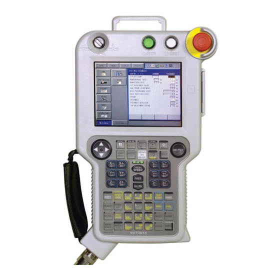
149235-1CD 1 Introduction 1.2 Programming Pendant Programming Pendant 1.2.1 Programming Pendant Overview The programming pendant is equipped with the keys and buttons used to conduct manipulator teaching operations and to edit jobs. Start button Hold button Emergency Mode switch stop button REMOTE TEACH START... -
Page 27: Key Description
149235-1CD 1 Introduction 1.2 Programming Pendant 1.2.2 Key Description Character Keys The keys which have characters printed on them are denoted with [ ]. For example, is shown as ENTER [ENTER]. The Numeric keys have additional functions along with their number values. Dual function keys are used in the context of the operation being performed. -
Page 28: Programming Pendant Keys
149235-1CD 1 Introduction 1.2 Programming Pendant 1.2.3 Programming Pendant Keys Turns OFF the servo power. E.STOP Button When the servo power is turned OFF, the SERVO ON LED on the programing pendant will extinguish. An emergency stop message is displayed on the screen. Turns ON the servo power. - Page 29 149235-1CD 1 Introduction 1.2 Programming Pendant Moves the cursor between “Menu Area” and “General Purpose Display Area.” When [SHIFT] is pressed simultaneously: • [SHIFT] + [AREA] [AREA] The language can be switched when the bilingual function is valid. (Bilingual function is optional.) •...
- Page 30 *: These modes are purchased options. Enables the robot axis operation. [ROBOT] [ROBOT] is active for the system where multiple manipulators are controlled by one NX100 or the system with external axes. ROBOT Enables the external axis (base axis or station axis) [EX.AXIS] operation.
- Page 31 149235-1CD 1 Introduction 1.2 Programming Pendant Moves the manipulator through the taught steps while this key is pressed. Only move instructions are executed (one instruction at a time, no welding instructions). [FWD] [INTERLOCK] + [FWD] All instructions are executed. [REFP] + [FWD] Moves to the reference point of the cursor line.
- Page 32 149235-1CD 1 Introduction 1.2 Programming Pendant Changes the functions of other keys by pressing together. [SHIFT] Can be used with [MAIN MENU], [COORD], [MOTION TYPE], cursor key, GO BACK Numeric key, page key to access alternate functions. SHIFT PAGE Refer to the description of each key for the alternate [SHIFT] functions. Changes the functions of other keys by pressing together.
- Page 33 149235-1CD 1 Introduction 1.2 Programming Pendant Displays the main menu. If this button is pressed while the main menu is displayed, the main menu [MAIN MENU] disappears. MAIN MENU [SHIFT] + [MAIN MENU] While a window opens, the window is switched in the following order: Window →...
-
Page 34: Programming Pendant Display
149235-1CD 1 Introduction 1.2 Programming Pendant 1.2.4 Programming Pendant Display The Five Display Areas The programming pendant display is a 6.5 inch color display. Alphanumeric characters can be used. The general display area, menu area, human interface display area, and main menu area among the following five areas can be moved by pressing [AREA], or can be selected by directly touching the screen. -
Page 35: General-Purpose Display Area
149235-1CD 1 Introduction 1.2 Programming Pendant General-purpose Display Area On the general-purpose display area, various settings and contents such as jobs and characteristics files can be displayed and edited. The operation buttons are also displayed at the bottom of the window according to the window contents. -
Page 36: Main Menu Area
149235-1CD 1 Introduction 1.2 Programming Pendant Main Menu Area Each menu and submenu are displayed in the main menu area. Press [MAIN MENU] or touch {Main Menu} on the left bottom of the window to display the main menu. FD/CF DOUT MOVE... - Page 37 149235-1CD 1 Introduction 1.2 Programming Pendant Manual Speed Displays the selected speed. For details, refer to " Select Manual Speed ".” “ : Inching : Low Speed : Medium Speed : High Speed Security Mode : Operation Mode : Edit Mode : Management Mode Operation Cycle Displays the present operation cycle.
-
Page 38: Human Interface Display Area
149235-1CD 1 Introduction 1.2 Programming Pendant Human Interface Display Area When two or more errors or messages are displayed, appears in the human interface display area. Turn on servo power To view the list of current errors or messages, activate the human interface display area and press [SELECT]. -
Page 39: Screen
149235-1CD 1 Introduction 1.2 Programming Pendant Screen The window can be displayed according to the view desired. DATA EDIT DISPLAY UTILITY Main Menu Short Cut Full Window View DATA EDIT DISPLAY UTILITY Upper Window View Middle Window View Main Menu Short Cut Lower Window View 1.2.6... -
Page 40: Operation
149235-1CD 1 Introduction 1.2 Programming Pendant Operation Button on the Keypad Programming Explanation Pendant Moves the cursor (focus). Cursor Selects a character. [SELECT] S E L E C T Clears all the characters being typed. Pressing this second time cancels the software keypad. [CANCEL] CANCEL Deletes the last one character. -
Page 41: Alphanumeric Input
149235-1CD 1 Introduction 1.2 Programming Pendant Alphanumeric Input Number input is performed with the Numeric keys or on the following alphanumeric input window. Numbers include 0 to 9, the decimal point (.), and the minus sign/hyphen (-). Note however, that the decimal point cannot be used in job names. GO BACK Press the page key to display the alphanumeric input window. -
Page 42: Modes
149235-1CD 1 Introduction 1.3 Modes Modes The following three modes are available for NX100. • Teach Mode • Play Mode • Remote Mode 1.3.1 Teach Mode In the teach mode, the following can be done. • Preparation and teaching of a job •... -
Page 43: About The Security Mode
1.4.1 Types of Security Modes The following three types of security modes are available for NX100. Any operations in the edit mode and the management mode require a password. The password must contain between 4 and 8 letters, numbers, or symbols. - Page 44 149235-1CD 1 Introduction 1.4 About the Security Mode Menu & Security Mode Security Mode Main Menu Sub Menu DISPLAY EDIT Operation Edit SELECT JOB Operation Operation Edit Edit CREATE NEW JOB MASTER JOB Operation Edit JOB CAPACITY Operation Edit Edit RES.
- Page 45 149235-1CD 1 Introduction 1.4 About the Security Mode Menu & Security Mode Security Mode Main Menu Sub Menu DISPLAY EDIT ROBOT CURRENT POSITION Operation COMMAND POSITION Operation SERVO MONITOR Management WORK HOME POS Operation Edit SECOND HOME POS Operation Edit DROP AMOUNT Management Management...
- Page 46 149235-1CD 1 Introduction 1.4 About the Security Mode Menu & Security Mode Security Mode Main Menu Sub Menu DISPLAY EDIT PARAMETER S1CxG Management Management Management Management Management Management Management Management Management Management Management Management Management Management Management Management Management Management Management Management Management...
- Page 47 149235-1CD 1 Introduction 1.4 About the Security Mode Menu & Security Mode Security Mode Main Menu Sub Menu DISPLAY EDIT SPOT WELDING WELD DIAGNOSIS Operation Edit (MOTOR GUN) GUN PRESSURE Edit Edit PRESSURE Edit Edit I/O ALLOCATION Management Management GUN CONDITION Management Management CLEARANCE SETTING...
-
Page 48: Switching Security Modes
149235-1CD 1 Introduction 1.4 About the Security Mode 1.4.2 Switching Security Modes Operation Explanation Select {SYSTEM INFO} The sub menu appears. under the main menu. DATA EDIT DISPLAY UTILITY FD/CF DOUT MOVE ARC WELDING PARAMETER VERSION VARIABLE SETUP B001 MONITORING TIME IN/OUT DISPLAY SETUP ALARM HISTORY... - Page 49 149235-1CD 1 Introduction 1.4 About the Security Mode Operation Explanation Input user ID as required. At the factory, the user ID number is preset as follows: • Edit Mode: [00000000] • Management Mode: [99999999] Press [ENTER]. The selected security mode’s input ID is checked. If the correct user ID is input, the security mode is changed.
-
Page 50: Control Groups And Coordinate Systems
2.1.1 Control Group For the NX100, a group of axes to be controlled at a time is called “Control Group”, and the group is classified into three units: “ROBOT” as a manipulator itself, “BASE” that moves the manipulator in parallel, and “STATION” as jigs or tools other than “ROBOT” and “BASE”. BASE and STATION are also called external axes. -
Page 51: Types Of Coordinate Systems
149235-1CD 2 Manipulator Coordinate Systems and Operations 2.1 Control Groups and Coordinate Systems 2.1.2 Types of Coordinate Systems The following coordinate systems can be used to operate the manipulator: • Joint Coordinates Each axis of the manipulator moves independently. • Cartesian Coordinates The tool tip of the manipulator moves parallel to any of the X-, Y-, and Z-axes. -
Page 52: General Operations
2.2 General Operations General Operations Check Safety Before any operation of NX100, read Section 1 “Safety” of “NX100 INSTRUCTIONS” again and keep safe around robot system or peripherals. Select Teach Mode Set the mode switch on the programming pendant to “teach”. -
Page 53: Servo On
149235-1CD 2 Manipulator Coordinate Systems and Operations 2.2 General Operations Servo ON Press [SERVO ON READY], then SERVO ON LED starts blinking. Squeeze the Enable switch, then SERVO ON LED starts lighting. Axis Operation Make sure of safety around the manipulator. Press axis key, then axis moves according to the selected control group, coordinates, and manual speed. -
Page 54: Coordinate Systems And Axis Operation
149235-1CD 2 Manipulator Coordinate Systems and Operations 2.3 Coordinate Systems and Axis Operation Coordinate Systems and Axis Operation 2.3.1 Joint Coordinates When operating in joint coordinates mode, the S, L, U, R, B, and T-axes of the manipulator move independently. The motion of each axis is described in the table below. Axis Motion in Joint Coordinates Axis Name Axis Operation Key... -
Page 55: Cartesian Coordinates
149235-1CD 2 Manipulator Coordinate Systems and Operations 2.3 Coordinate Systems and Axis Operation 2.3.2 Cartesian Coordinates In the cartesian coordinates, the manipulator moves parallel to the X-, Y-, or Z-axes. The motion of each axis is described in the following table: Axis Motion in Cartesian Coordinates Axis Name Axis Operation Key... -
Page 56: Cylindrical Coordinates
149235-1CD 2 Manipulator Coordinate Systems and Operations 2.3 Coordinate Systems and Axis Operation 2.3.3 Cylindrical Coordinates In the cylindrical coordinates, the manipulator moves as follows. The motion of each axis is described in the following table. Axis Motion in Cylindrical Coordinates Axis Name Axis Operation Key Motion... -
Page 57: Tool Coordinates
149235-1CD 2 Manipulator Coordinate Systems and Operations 2.3 Coordinate Systems and Axis Operation 2.3.4 Tool Coordinates In the tool coordinates, the manipulator moves parallel to the X-, Y-, and Z-axes, which are defined at the tip of the tool. The motion of each axis is shown in the following table: Axis Motion in Tool Coordinates Axis Name Axis Operation Key... -
Page 58: Selecting The Tool
2 Manipulator Coordinate Systems and Operations 2.3 Coordinate Systems and Axis Operation For tool coordinates, the tool file should be registered in advance. For further details, refer SUPPLE to section 8.3 “Tool Data Setting” of coordinates in the “NX100 INSTRUCTIONS”. -MENT Selecting the Tool ... -
Page 59: User Coordinates
149235-1CD 2 Manipulator Coordinate Systems and Operations 2.3 Coordinate Systems and Axis Operation 2.3.5 User Coordinates In the user coordinates, the manipulator moves parallel to each axis of the coordinates which are set by the user. Up to 24 coordinate types can be registered. Each coordinate has a user number and is called a user coordinate file. -
Page 60: Selecting User Coordinates
USER COORD SELECT NAME Main Menu Short Cut For more information on registration of the user SUPPLE coordinates, refer to section 8.8 “User Coordinate -MENT Setting” of the “NX100 INSTRUCTIONS”. Select the desired user number. 2-11 60 of 493 RE-CSO-A031... -
Page 61: Examples Of User Coordinate Utilization
149235-1CD 2 Manipulator Coordinate Systems and Operations 2.3 Coordinate Systems and Axis Operation Examples of User Coordinate Utilization The user coordinate settings allow easy teaching in various situations. For example: • When multiple positioners are used, manual operation can be simplified by setting the user coordinates for each fixture. Fixture U s e r c o o r d i n a t e s Fixture... -
Page 62: Control Point Operation
149235-1CD 2 Manipulator Coordinate Systems and Operations 2.3 Coordinate Systems and Axis Operation 2.3.7 Control Point Operation Motion about TCP (Tool Center Point) can only change the wrist orientaion at a fixed TCP position in all coordinate systems except the joint coordinates. The motion of each axis is described in the following table. - Page 63 149235-1CD 2 Manipulator Coordinate Systems and Operations 2.3 Coordinate Systems and Axis Operation • In cartesian or cylindrical coordinates, wrist axis rotations are based on the X-, Y-, or Z- axis. Z - a x i s − Y- a x i s −...
-
Page 64: Control Point Change
TCPs alternately, the workpieces can be moved as shown below: Workpiece Workpiece Motion about TCP with P1 selected Motion about TCP with P2 selected For registration of the tool file, refer to section 8.3 “Tool Data Setting” of the “NX100 SUPPLE INSTRUCTIONS”. -MENT 2-15... -
Page 65: Preparation For Teaching
The Servo ON button on the programming pendant should be lit while the power is ON for the servo system. Perform the following operation to ensure that the emergency stop buttons on both the NX100 and the programming pendant are functioning correctly before operating the manipulator. -
Page 66: Registering A Job
149235-1CD 3 Teaching 3.1 Preparation for Teaching 3.1.3 Registering a Job Specify the name, comments (as required), and control group to register a job. Registering Job Names Job names can use up to 8 alphanumeric and symbol characters. These different types of characters can coexist within the same job name. -
Page 67: Registering Comments
149235-1CD 3 Teaching 3.1 Preparation for Teaching Registering Comments Register a comment using up to 32 alphanumeric and symbol characters as required. Operation Explanation In the NEW JOB CREATE window, move the cursor to the comment and press [SELECT]. Enter the comment. -
Page 68: Teaching Operation
149235-1CD 3 Teaching 3.2 Teaching Operation Teaching Operation 3.2.1 The Teaching Window Teaching is conducted in the JOB CONTENT window. The JOB CONTENT window contains the following items: EDIT DISPLAY UTILITY JOB CONTENT JOB NAME : TEST01 STEP NO. : 0003 CONTROL GROUP : R1 TOOL : 00 0000 NOP... -
Page 69: Interpolation Type And Play Speed
149235-1CD 3 Teaching 3.2 Teaching Operation 3.2.2 Interpolation Type and Play Speed Interpolation type determines the path along which the manipulator moves between playback steps. Play speed is the rate at which the manipulator moves. Normally the three elements of position data, Interpolation type, and play speed are registered for the robot axes steps at one time. -
Page 70: Linear Interpolation
149235-1CD 3 Teaching 3.2 Teaching Operation Linear Interpolation The manipulator moves in a linear path from one taught step to the next. When the linear interpolation is used to teach a robot axis, the move instruction is MOVL. Linear interpolation is used for work such as welding. -
Page 71: Circular Interpolation
149235-1CD 3 Teaching 3.2 Teaching Operation Circular Interpolation The manipulator moves in an arc that passes through three points. When circular interpolation is used for teaching a robot axis, the move instruction is MOVC. Single Circular Arc When a single circular movement is required, teach the circular interpolation for three points, P1 to P3, as shown in the following figure. -
Page 72: Spline Interpolation
149235-1CD 3 Teaching 3.2 Teaching Operation Spline Interpolation When performing operations such as welding, cutting, and applying primer, using the spline interpolation makes teaching for workpieces with irregular shapes easier. The path of motion is a parabola passing through three points. When spline interpolation is used for teaching a robot axis, the move instruction is MOVS. -
Page 73: Teaching Steps
149235-1CD 3 Teaching 3.2 Teaching Operation Play Speed The play speed setting window is identical to that for the linear interpolation. As with the circular interpolation, the speed taught at P2 is applied from P1 to P2, and the speed taught at P3 is applied from P2 to P3. - Page 74 149235-1CD 3 Teaching 3.2 Teaching Operation Setting the Position Data Operation Explanation Select {JOB} under the main The sub-menu appears. menu. EDIT DISPLAY UTILITY FD/CF DOUT JOB CONTENT MOVE DOUT MOVE SETUP ARC WELDING SELECT JOB VARIABLE DISPLAY SETUP CREATE NEW JOB B001 MASTER JOB IN/OUT...
- Page 75 149235-1CD 3 Teaching 3.2 Teaching Operation Selecting the Tool Number Operation Explanation Press [SHIFT] + [COORD]. When selecting the “JOINT,” “XYZ/CYLINDRICAL,” or “TOOL” coordinates, press [SHIFT] + [COORD] and the TOOL NO. SELECT window will be shown. DATA EDIT DISPLAY UTILITY TOOL NO.
- Page 76 149235-1CD 3 Teaching 3.2 Teaching Operation Setting the Play Speed Operation Explanation Move the cursor to the 0001 MOVJ=50.00 instruction. Press [SELECT]. The cursor moves to the input buffer line. MOVJ VJ=50.00 Move the cursor to the play speed to be set. Press [SHIFT] + the cursor key The joint speed moves up and down.
- Page 77 149235-1CD 3 Teaching 3.2 Teaching Operation Operation Explanation Select move instruction. The DETAIL EDIT window appears. EDIT DISPLAY UTILITY DETAIL EDIT MOVJ JOINT SPEED VJ= 50.00 POS LEVEL UNUSED NWAIT UNUSED Main Menu Short Cut Select the position level The selection dialog box appears. “UNUSED.”...
- Page 78 149235-1CD 3 Teaching 3.2 Teaching Operation Operation Explanation Press [ENTER]. To change the position level, select the level in the input buffer line, type the value using the Numeric keys, and press [ENTER]. The position levels move instruction is registered. EDIT DISPLAY UTILITY...
-
Page 79: Registering Reference Point Instructions
149235-1CD 3 Teaching 3.2 Teaching Operation Registering Reference Point Instructions Reference point instructions (REFP) set an auxiliary point such as a wall point for weaving. Reference point Nos. 1 to 8 are assigned for each application. Follow these procedures to register reference point instructions. -
Page 80: Registering Timer Instructions
149235-1CD 3 Teaching 3.2 Teaching Operation Registering Timer Instructions The timer instruction stops the manipulator for a specified time. Follow these procedures to register timer instructions. Operation Explanation Select {JOB} under the main menu. Select {JOB}. Move the cursor. Move the cursor to one line before the position where the timer instruction is to be registered. - Page 81 149235-1CD 3 Teaching 3.2 Teaching Operation Changing Timer Value Operation Explanation Press [TIMER]. Press [SELECT]. The DETAIL EDIT window for the TIMER instruction appears. EDIT DISPLAY UTILITY DETAIL EDIT TIMER TIME 1.00 Main Menu Short Cut Input the timer value on the When is selected, the items available to be changed are instruction DETAIL EDIT...
-
Page 82: Overlapping The First And Last Steps
149235-1CD 3 Teaching 3.2 Teaching Operation 3.2.4 Overlapping the First and Last Steps Why is overlapping the first and last step necessary? SUPPLE -MENT Assume that the job shown below is to be repeated. The manipulator moves from the last step (Step 6) to the first step (Step 1). -
Page 83: Checking Steps
149235-1CD 3 Teaching 3.3 Checking Steps Checking Steps 3.3.1 FWD/BWD Key Operations Check whether the position of the taught steps is appropriate using [FWD] or [BWD] on the programming pendant. Each time [FWD] or [BWD] is pressed, the manipulator moves by a single step. [FWD]: Moves the manipulator ahead in step number sequence. - Page 84 149235-1CD 3 Teaching 3.3 Checking Steps BWD Movements • The manipulator moves in reverse step number sequence. Only move instructions are executed. • The manipulator stops after playing a single cycle. It does not move after the first step is reached, even if [BWD] is pressed.
-
Page 85: Selecting Manual Speed
149235-1CD 3 Teaching 3.3 Checking Steps Linear motion : Motion path for FWD/BWD key operation : Motion using axis keys : Motion path during playback • If the manipulator is moved to P3 with [FWD], stopped, and then returned to P2 with [BWD], the path followed between P2 and P3 is different for each of the following: the first FWD operation, the BWD operation, and the consequent FWD operation. -
Page 86: Moving To Reference Point
149235-1CD 3 Teaching 3.3 Checking Steps Moving to Reference Point To check the position of a taught reference point, follow these procedures to move the manipulator to the reference point. Operation Explanation Move the cursor to the reference point instruction line to be checked. -
Page 87: Modifying Steps
149235-1CD 3 Teaching 3.4 Modifying Steps Modifying Steps Begin move instruction Begin move instruction insertion. deletion. Move step cursor to Move cursor to location of location where you want instruction to be deleted. to insert the instruction. Press [DELETE]. Perform axis operations. Set interpolation type. - Page 88 149235-1CD 3 Teaching 3.4 Modifying Steps Begin Move instruction modification. Move step cursor to step to be modified. Modifying position data Modifying interpolation type Move to position to be Perform axis modified using the operations to position axis operation keys. to be modified.
- Page 89 149235-1CD 3 Teaching 3.4 Modifying Steps Begin REFP instruction modification. Deletions Modifications Move step cursor to the Move step cursor to the REFP instruction to be REFP instruction to be deleted,and move the modified. manipulator to the position. Perform axis operations. Press [DELETE].
- Page 90 149235-1CD 3 Teaching 3.4 Modifying Steps Begin TIMER Instruction Modification. Deletions Modification Move edit cursor to the Move edit cursor to the TIMER instruction to be TIMER instruction to be deleted. modified. Press [DELETE]. Press [TIMER]. Press [ENTER]. Enter timer value. Deletion completed.
-
Page 91: Displaying The Job Content Window For Editing
149235-1CD 3 Teaching 3.4 Modifying Steps 3.4.1 Displaying the JOB CONTENT Window for Editing Currently Called Up Job Operation Explanation Select {JOB} under the main menu. Select {JOB}. The JOB CONTENT window appears. Calling Up Other Jobs NOTE In any other than the teach mode, set the mode switch to “TEACH.”... -
Page 92: Inserting Move Instructions
149235-1CD 3 Teaching 3.4 Modifying Steps 3.4.2 Inserting Move Instructions NOTE Move instructions cannot be inserted when the servo power is OFF. Step where move instruction is to be inserted Path after insertion Path before insertion Operation Explanation Move the cursor to the line The line immediately immediately before the insert 0006... -
Page 93: Deleting Move Instructions
149235-1CD 3 Teaching 3.4 Modifying Steps Positions where the move instructions are inserted. NOTE The default location for insertions is for “before the next step,” but it is also possible to insert “after the cursor line.” This setting is made in the “Move Instruction Register Method” in the TEACHING CONDITION window. -
Page 94: Modifying Move Instructions
149235-1CD 3 Teaching 3.4 Modifying Steps 3.4.4 Modifying Move Instructions Modifying Position Data Operation Explanation Move the cursor to the MOV Display the JOB CONTENT window and move the cursor to the instruction to be modified. move instruction to be changed. Press the axis operation key. -
Page 95: Undo Operation
149235-1CD 3 Teaching 3.4 Modifying Steps 3.4.5 Undo Operation After inserting, deleting, or modifying an instruction, the operation can be undone. The UNDO operation becomes enabled by selecting {EDIT} {ENABLE UNDO}, and becomes ∗ disabled by selecting {EDIT} ENABLE UNDO} while editing a job. -
Page 96: Modifying Reference Point Instructions
149235-1CD 3 Teaching 3.4 Modifying Steps Modifying Reference Point Instructions Operation Explanation Move the cursor to the reference point instruction to be modified. Move the manipulator with the Turn ON the servo power and use the axis operation keys to axis operation keys. -
Page 97: Modifying Timer Instructions
149235-1CD 3 Teaching 3.4 Modifying Steps Modifying Timer Instructions Operation Explanation Move the cursor to the timer 0003 MOVJ VJ=50.00 instruction to be modified. 0004 TIMER T=0.50 0005 MOVL VJ=138 0006 MOVL VJ=138 Press [TIMER]. 0003 MOVJ VJ=50.00 0004 TIMER T=0.50 0005... -
Page 98: Modifying Jobs
149235-1CD 3 Teaching 3.5 Modifying Jobs Modifying Jobs 3.5.1 Calling Up a Job Operation Explanation Select {JOB} under the main menu. Select {SELECT JOB}. The JOB LIST window appears. EDIT DISPLAY UTILITY JOB LIST TEST3A-! TEST03 TEST3A TEST02 TEST TEST01 Main Menu Short Cut Turn on servo power... - Page 99 149235-1CD 3 Teaching 3.5 Modifying Jobs Operation Explanation Select {DISPLAY} under the menu. Select {JOB HEADER}. The JOB HEADER window appears. Scroll the window using the cursor. EDIT DISPLAY UTILITY JOB HEADER JOB NAME :TEST01 COMMENT This is test job ...
-
Page 100: Job Content Window
149235-1CD 3 Teaching 3.5 Modifying Jobs JOB CONTENT Window Operation Explanation Select {JOB} under the main menu. Select {JOB}. The JOB CONTENT window appears. The cursor is moved to the address area. (Left) : The cursor is moved to the instruction area. ... -
Page 101: Command Position Window
149235-1CD 3 Teaching 3.5 Modifying Jobs COMMAND POSITION Window Operation Explanation Select {ROBOT} under the main menu. Select {COMMAND Edit operations cannot be conducted from this window, but the POSITION}. taught play speed and position data can be viewed on this window. -
Page 102: Job Capacity Window
NUMBER OF JOBS Displays the total number of jobs currently registered in the memory of NX100. USED MEMORY Displays the total amount of memory used in the NX100. STEPS Displays the total number of used steps. EDITING BUFFER Displays editing buffer use. -
Page 103: Editing Instructions
149235-1CD 3 Teaching 3.6 Editing Instructions Editing Instructions The content of editing differs depending on where the cursor is in the address area or instruction area. EDIT DISPLAY UTILITY JOB CONTENT JOB NAME :TEST01 STEP NO. : 0003 CONTROL GROUP : R1 TOOL : * 0000 0001... - Page 104 149235-1CD 3 Teaching 3.6 Editing Instructions Instruction Display Contents Example Group IN/OUT I/O Instructions Controls input and output DOUT, WAIT CONTROL Control Controls processing or each work JUMP, TIMER Instructions DEVICE Work Operates arc welding, spot welding, handling, ARCON, WVON, Instructions painting, etc.
-
Page 105: Inserting Instructions
149235-1CD 3 Teaching 3.6 Editing Instructions 3.6.2 Inserting Instructions Operation Explanation Move the cursor to the Move the cursor to the line immediately before where the address area in the JOB instruction is to be inserted, in the teach mode. CONTENT window. -
Page 106
149235-1CD 3 Teaching 3.6 Editing Instructions Operation Explanation Change the data of additional
items or variables as required. Proceed to Step 6. • Changing numeric data Move the cursor to the desired item and press [SHIFT] + the cursor key to increase or decrease the value. - Page 107 149235-1CD 3 Teaching 3.6 Editing Instructions Operation Explanation (cont’d) • Changing the data type To change the data type of an additional item, move the cursor of the item and press [SELECT]. The data type list appears. Select the desired data type. DATA EDIT DISPLAY...
-
Page 108: Deleting Instructions
149235-1CD 3 Teaching 3.6 Editing Instructions 3.6.3 Deleting Instructions Operation Explanation Move the cursor to the Move the cursor to the instruction line to be deleted, in the teach address area in the JOB mode. CONTENT window. Move the cursor to the deleting line in the address 0020 MOVL V=138... -
Page 109
149235-1CD 3 Teaching 3.6 Editing Instructions Operation Explanation Change the data of additional
items or variables as required. • Changing numeric data Move the cursor to the desired item and press [SHIFT] + the cursor key to increase or decrease the value. PULSE OT#( To directly input the value using Numeric keys, press [SELECT] to display the input buffer line. - Page 110 149235-1CD 3 Teaching 3.6 Editing Instructions Operation Explanation (cont’d) • Changing the data type To change the data type of an additional item, move the cursor of the item and press [SELECT]. The data type list appears. Select the desired data type. DATA EDIT DISPLAY...
-
Page 111: Modifying Additional Numeric Data
149235-1CD 3 Teaching 3.6 Editing Instructions 3.6.5 Modifying Additional Numeric Data Operation Explanation Mote the cursor to the instruction area in the JOB CONTENT window. Select the line where the The selected line can now be edited. number data is to be modified. 0017 TIMER T=1.00 0018... -
Page 112: Modifying Additional Items
149235-1CD 3 Teaching 3.6 Editing Instructions 3.6.6 Modifying Additional Items Operation Explanation Move the cursor to the instruction area in the JOB CONTENT window. Select the instruction line for The selected line can now be edited. which the additional item is to 0017 TIMER T=1.00 be modified. -
Page 113: Inserting Additional Items
149235-1CD 3 Teaching 3.6 Editing Instructions 3.6.7 Inserting Additional Items Operation Explanation Move the cursor to the instruction area in the JOB CONTENT window. Select the instruction line for The selected line can now be edited. which the additional item is to 0017 TIMER T=1.00 be inserted. -
Page 114: Deleting Additional Items
149235-1CD 3 Teaching 3.6 Editing Instructions 3.6.8 Deleting Additional Items NOTE This operation cannot be used for the additional item which is locked. Operation Explanation Move the cursor to the instruction area in the JOB CONTENT window. Select the line where the The selected line can be now be edited. -
Page 115: Editing Jobs
149235-1CD 3 Teaching 3.7 Editing Jobs Editing Jobs The following five operations are to edit jobs. Copy :Copies a specified range to the buffer. :Copies a specified range from a job to the buffer, and deletes it in a job. Paste :Inserts the contents of the buffer into a job. - Page 116 149235-1CD 3 Teaching 3.7 Editing Jobs 0000 0001 ’TEST JOB MOVJ VJ=50.00 Copy 0002 MOVJ VJ=50.00 TIMER T=1.00 0003 TIMER T=1.00 MOVL V=100 0004 MOVL V=100 0005 MOVL V=100 0000 0001 ’TEST JOB 0005 MOVL V=100 0000 0001 ’TEST JOB Paste 0002 MOVJ VJ=50.00...
-
Page 117: Selecting The Range
149235-1CD 3 Teaching 3.7 Editing Jobs 3.7.1 Selecting the Range After setting the range, Copy and Delete can be performed. Operation Explanation Move the cursor to the instruction area in the JOB EDIT DISPLAY UTILITY CONTENT window. JOB CONTENT JOB NAME :TEST01 STEP NO. -
Page 118: Copying
149235-1CD 3 Teaching 3.7 Editing Jobs 3.7.2 Copying Before copying, the range to be copied has to be specified. Operation Explanation Select {EDIT} under the menu. The pull-down menu appears. EDIT DISPLAY UTILITY JOB CONENT COPY JOB NAMETEST01 STEP NO. : 0003 CONTROL GROUPR1 TOOL : 00 0000... -
Page 119: Pasting
149235-1CD 3 Teaching 3.7 Editing Jobs 3.7.4 Pasting Before pasting, the range to be pasted has to be stored in the buffer. Operation Explanation Move the cursor to the line immediately before the desired position in the JOB CONTENT window. Select {EDIT} under the menu. -
Page 120: Reverse Pasting
149235-1CD 3 Teaching 3.7 Editing Jobs 3.7.5 Reverse Pasting Before pasting, the range to be pasted has to be stored in the buffer. Operation Explanation Move the cursor to the line immediately before the desired position in the JOB CONTENT window. Select {EDIT} under the menu. -
Page 121: Test Operations
149235-1CD 3 Teaching 3.8 Test Operations Test Operations Playback operations can be simulated in the teach mode with test operations. This function is convenient for checking continuous paths and operation instructions. Test operation differs in the following ways from actual playback in the play mode. •... -
Page 122: Other Job-Editing Functions
149235-1CD 3 Teaching 3.9 Other Job-editing Functions Other Job-editing Functions 3.9.1 Editing Play Speed There are two ways to modify play speed: • Modification of Speed Type • Relative Modification Modification of Speed Type This method is used to modify the speed type (such as VJ, V, VR, etc.). 0005 MOVJ VJ=25.00 0006... - Page 123 149235-1CD 3 Teaching 3.9 Other Job-editing Functions Operation Explanation Move the cursor to the instruction area. Press [SHIFT] + [SELECT] in If the section is not specified, the speed of the entire job will be the speed modify start line. changed.
-
Page 124: Modification By Trt (Traverse Time)
149235-1CD 3 Teaching 3.9 Other Job-editing Functions Modification by TRT (Traverse Time) Modifications made by TRT have the following characteristics: • By setting the time required to execute a move instruction (moving time) to a desired value, the speeds can be modified. •... - Page 125 149235-1CD 3 Teaching 3.9 Other Job-editing Functions Operation Explanation Select “EXECUTE.” The speed is changed according to the setting. • If instructions that include specific speed data NOTE such as SPEED or ARCON instructions (including speed data of the welding condition file) exist in the specified section, the speed data for those steps are not changed.
-
Page 126: Editing Interpolation Type
149235-1CD 3 Teaching 3.9 Other Job-editing Functions 3.9.2 Editing Interpolation Type Operation Explanation Select {JOB} under the main menu. Select {JOB}. The JOB CONTENT window appears. Move the cursor to the instruction area. Select the line to be modified. The instruction on the cursor is displayed in the input buffer line. EDIT DISPLAY UTILITY... -
Page 127: Editing Condition Files
The patterns are listed by “condition numbers.” This number is specified by the work instruction in a job. Refer to NX100 Operator’s Manual of each application for information regarding the NOTE contents and editing methods of the condition file. -
Page 128: User Variables
149235-1CD 3 Teaching 3.9 Other Job-editing Functions 3.9.4 User Variables User variables are used for jobs to store counters, calculation results or input signals. Since the same user variable can be used in multiple jobs, save the numerical values as common references for the jobs and the user variables are maintained even when the power is turned OFF. - Page 129 149235-1CD 3 Teaching 3.9 Other Job-editing Functions • Play Speed V: NOTE MOVL V=I000 The variable I000 is used for speed V with this move instruction. The unit for V is 0.1mm per second. For example, if I000 were set as 1000, the following would be true: I000=1000 ...
-
Page 130: And Real Type Variables
149235-1CD 3 Teaching 3.9 Other Job-editing Functions Setting Byte, Integer, Double Precision Integer, and Real Type Variables Operation Explanation Select {VARIABLE} under the {BYTE}, {INTEGER}, {DOUBLE}, and {REAL} are displayed for main menu. the sub menu. Select desired variable type. The BYTE VARIABLE window appears. -
Page 131: Setting Character Type Variables
149235-1CD 3 Teaching 3.9 Other Job-editing Functions Setting Character Type Variables Operation Explanation Select {VARIABLE} under the main menu. Select {STRING}. The STRING VARIABLE window appears. DATA EDIT DISPLAY UTILITY STRING VARIABLE CONTENT NAME S000 S001 S002 S003 S004 S005 S006 S007... -
Page 132: Registering Variable Name
149235-1CD 3 Teaching 3.9 Other Job-editing Functions Registering Variable Name Operation Explanation Select {VARIABLE} under the main menu. Select desired variable. Select any variable type from among byte type, integer type, double precision integer type, real type, robot position type, base position type, and station position type. -
Page 133: Displaying Position Variables
149235-1CD 3 Teaching 3.9 Other Job-editing Functions Displaying Position Variables Operation Explanation Select {VARIABLE} under the main menu. Select desired position The POSITION VARIABLE window of desired type among robot variable type. type, base type, and station type appears. DATA EDIT DISPLAY... -
Page 134: Setting Position Variables
149235-1CD 3 Teaching 3.9 Other Job-editing Functions Setting Position Variables The following table shows the types of position variables and setting methods. The setting of position variables is done in the teach mode. NOTE Turn the servo power ON when setting the variables with the axis keys. Types of Position Variables and Setting Methods BPxxx EXxxx... -
Page 135: Setting Position Variables Using The Numeric Keys
149235-1CD 3 Teaching 3.9 Other Job-editing Functions Setting Position Variables Using the Numeric Keys Pulse Type Operation Explanation Select {VARIABLE} under the main menu. Select desired position The desired variable window appears (robot, base, or station). variable type. (The POSITION VARIABLE window is used for this example.) DATA EDIT DISPLAY... - Page 136 149235-1CD 3 Teaching 3.9 Other Job-editing Functions XYZ Type Operation Explanation Select {VARIABLE} under the main menu. Select desired position variable type. Select the variable data type. The selection dialog box appears. NAME #P000 PULSE BASE ROBOT USER TOOL MASTER TOOL Select desired coordinates except PULSE.
-
Page 137: Setting Position Variables Using The Axis Keys
149235-1CD 3 Teaching 3.9 Other Job-editing Functions Setting Position Variables Using the Axis Keys Pulse Type Operation Explanation Select {VARIABLE} under the main menu. Select desired position The desired variable window appears (robot, base, or station). variable type. Press [SHIFT] + [ROBOT]. When you need an external axis position, press [SHIFT]+[EX.AXIS]. -
Page 138: Deleting Data Set Of Position Variables
149235-1CD 3 Teaching 3.9 Other Job-editing Functions Deleting Data Set of Position Variables Operation Explanation Select {VARIABLE} under the main menu Select desired position variable type Select {DATA} under the The pull-down menu appears. menu DATA EDIT DISPLAY UTILITY CLEAR DATA NAME #P000... -
Page 139: Checking Positions By Position Variables
149235-1CD 3 Teaching 3.9 Other Job-editing Functions Checking Positions by Position Variables Operation Explanation Select {VARIABLE} under the main menu. Select desired position When there are two or more robot, base, or a station, specify the variable type. axis with following operation. •... -
Page 140: Manipulator Types
In order to select one appropriate solution, it is necessary to specify the manipulator type. This manipulator type is called “Type.” There are up to six types in NX100 system. These types also vary according to the manipulator models. • Flip/No Flip: R-axis Position •... - Page 141 149235-1CD 3 Teaching 3.9 Other Job-editing Functions • R-axis Angle This specifies whether the R-axis angle is less than ±180 or greater than ±180 ° ° ° ° R ≥ 180 R < 180 0° 0° 360° -360° -180° 180° -180 <...
- Page 142 149235-1CD 3 Teaching 3.9 Other Job-editing Functions • Front/Back This specifies where in the S-axis rotation center the B-axis rotation center locates when viewing the L-axis and U-axis from the right-hand side. When viewed from the right-hand side, the right of the S-axis rotation center is called the front, and the left is called the back.
- Page 143 149235-1CD 3 Teaching 3.9 Other Job-editing Functions • Upper Arm/Lower Arm This specifies a type comprised of L-axis and U-axis when the L-axis and U-axis are viewed from the right-hand side. Right-hand side Upper Arm Lower Arm • S-axis Angle This designation is required for the manipulators which have working envelopes greater than ±180°.
-
Page 144: Editing Local Variables
149235-1CD 3 Teaching 3.9 Other Job-editing Functions 3.9.5 Editing Local Variables User variables and local variables can be used in the storage of counters, calculations, and input signals. The data format is the same as that of user variables. As shown in the following table, the letter L is affixed to the variable number to indicate a local variable. - Page 145 149235-1CD 3 Teaching 3.9 Other Job-editing Functions • Not Able to Display the Variable Contents To display the local variable contents, user variables are needed. For example, to view the contents of local variable LP000, save it temporarily as user variable P001.
-
Page 146: Setting The Number Of Local Variables
Only when expanding the “INSTRUCTION LEVEL,” it is possible to use local variables. NOTE Refer to section 8.12 “Instruction Level Setting” of “NX100 INSTRUCTIONS” for details on setting the language level. Operation... -
Page 147: Searching
149235-1CD 3 Teaching 3.9 Other Job-editing Functions 3.9.6 Searching When performing editing or confirmation, a search for the job or step can be done. The search can be done when the cursor is in either the address or instruction area on the JOB CONTENT window. Operation Explanation Select {JOB} under the main... -
Page 148: Line Search
149235-1CD 3 Teaching 3.9 Other Job-editing Functions Line Search This function moves the cursor to the desired line number. Operation Explanation Select {EDIT], {SEARCH} and The input buffer line appears. “LINE SEARCH.” Input desired line number. Press [ENTER]. The cursor is moved to the line number and the window appears. EDIT DISPLAY UTILITY... -
Page 149: Label Search
149235-1CD 3 Teaching 3.9 Other Job-editing Functions Label Search This function searches for the desired label and the instruction using that label. Operation Explanation Select {EDIT}, {SEARCH} and The input buffer line appears. “LABEL SEARCH.” Input desired label name. For information on character input operation, refer to section 1.2.6 "Character Input"... -
Page 150: Instruction Search
149235-1CD 3 Teaching 3.9 Other Job-editing Functions Instruction Search This function moves the cursor to a desired instruction. Operation Explanation Select {EDIT}, {SEARCH} and The INFORM command list appears. “INSTRUCTION SEARCH.” EDIT DISPLAY UTILITY JOB CONTENT IN/OUT JOB NAME : TEST01 STEP NO.: 0003 CONTROL GROUP : R1 TOOL : 00... -
Page 151: Tag Search
149235-1CD 3 Teaching 3.9 Other Job-editing Functions Tag Search This function moves the cursor to the desired tag. Operation Explanation Select {EDIT}, {SEARCH} and The instruction list dialog box appears. “TAG SEARCH.” EDIT DISPLAY UTILITY JOB CONTENT IN/OUT JOB NAME : TEST01 STEP NO. - Page 152 149235-1CD 3 Teaching 3.9 Other Job-editing Functions Operation Explanation Use the cursor to continue It is possible to continue searching by pressing the cursor key. searching. To end searching, select {EDIT} {END SEARCH} on the menu and press [SELECT] or press [CANCEL]. DISPLAY EDIT UTILITY...
-
Page 153: Preparation For Playback
149235-1CD 4 Playback 4.1 Preparation for Playback 4 Playback Preparation for Playback 4.1.1 Selecting a Job Playback is the act of executing a taught job. Before playback operation, first call the job to be executed. Calling a Job Operation Explanation Select {JOB} under the main menu. -
Page 154: Registering The Master Job
149235-1CD 4 Playback 4.1 Preparation for Playback Registering the Master Job If a particular job is played back frequently, it is convenient to register that job as a master job (master registration). A job registered as the master job can be called more easily than the method described on the preceding page. -
Page 155: Calling The Master Job
149235-1CD 4 Playback 4.1 Preparation for Playback Operation Explanation Select {CALL MASTER JOB}. The JOB LIST window appears. EDIT DISPLAY UTILITY JOB LIST TEST3A-! TEST03 TEST3A TEST02 TEST TEST01 Main Menu Short Cut Select a job to be registered The selected job is registered as the master job. as a master job. - Page 156 149235-1CD 4 Playback 4.1 Preparation for Playback Calling from the MASTER JOB Window Operation Explanation Select {JOB} under the main menu. Select {MASTER JOB}. The MASTER JOB window appears. EDIT DISPLAY UTILITY MASTER JOB MASTER JOB : TEST01 Main Menu Short Cut Press [SELECT].
-
Page 157: The Playback Window
149235-1CD 4 Playback 4.1 Preparation for Playback 4.1.2 The PLAYBACK Window When the mode switch on the programming pendant is switched to “PLAY” while displaying the JOB CONTENT window, the PLAYBACK window appears. EDIT DISPLAY UTILITY JOB CONTENT JOB NAME : TEST01 STEP NO. -
Page 158: Display Of Cycle Time
149235-1CD 4 Playback 4.1 Preparation for Playback Display of Cycle Time Follow the procedure below to set whether or not to display the cycle time on the PLAYBACK window. Operation Explanation Select {DISPLAY} under the menu. Select {CYCLE TIME}. The cycle time is displayed. - Page 159 149235-1CD 4 Playback 4.1 Preparation for Playback Automatic Setting for Operation Cycle Automatic setting of the operation cycle can be changed by the following operation. This can be done in the management mode only. Operation Explanation Select {SETUP} under the main menu.
-
Page 160: Playback
149235-1CD 4 Playback 4.2 Playback Operation Explanation Select a cycle. The operation cycle set automatically is changed. UTILITY DATA EDIT DISPLAY OPERATING CONDITION MASTER JOB CHANGE PERMIT PROHIBIT RESERVED START RESERVED START JOB CHANGE PERMIT SPEED DATA INPUT FORM cm/min STEP CYCLE SWITCH IN TEACH MODE CYCLE SWITCH IN PLAY MODE... -
Page 161: Servo On
4 Playback 4.2 Playback Servo On Operation Explanation Press [Servo ON Ready]. NX100 servo power is ON and the Servo ON lamp on the programming pendant lights. Start Operation Operation Explanation Press [START]. The start button lamp lights and the manipulator begins operation. -
Page 162: Low Speed Operation
149235-1CD 4 Playback 4.2 Playback Low Speed Operation The manipulator moves at low speed during the first step after starting. After the operation of this step, the manipulator stops regardless of the selection of the operation cycle and when low speed operation is canceled. -
Page 163: Dry-Run Speed Operations
149235-1CD 4 Playback 4.2 Playback Dry-run Speed Operations The dry-run speed is a constant speed that is independent of the teaching speeds. The manipulator executes all the steps at a constant speed, which is convenient for quick check of a job consisting of slow operations. -
Page 164: Check Mode Operation
149235-1CD 4 Playback 4.2 Playback Check Mode Operation The machine runs without issuing work instructions, such as the ARCON instruction. It is used primarily to check the path of the program. Operation Explanation Select “CHECK-RUN” under The setting alternates between “VALID” and “INVALID.” the SPECIAL PLAY window. -
Page 165: Stop And Restart
149235-1CD 4 Playback 4.3 Stop and Restart Stop and Restart The manipulator stops in the following conditions: • Hold • Emergency stop • Stop by alarm • Others • During each application 4.3.1 Hold Hold operation causes the manipulator to stop all motion. [HOLD] lamp lights while it is held down. -
Page 166: Emergency Stop
The servo power turns OFF and the manipulator stops immediately. button EMERGENCY STOP On the front door of the NX100: On the programming pendant: Using the Emergency Stop Button on the Programming Pendant Robot stops by P.P. emergency stop Using the External Input Signal (System Input) -
Page 167: Restart After Emergency Stop
Explanation Turn the emergency stop TURN button in the direction On the front door of the NX100: of the arrows. TURN On the programming pendant: To turn ON the servo power supply again, press [SERVO ON READY] and then grip the Enable switch of the programming pendant. -
Page 168: Stop By Alarm
149235-1CD 4 Playback 4.3 Stop and Restart 4.3.3 Stop by Alarm If an alarm occurs during operation, the manipulator stops immediately and the ALARM window appears on the programming pendant indicating that the machine was stopped by an alarm. If more than one alarm occurs simultaneously, all alarms can be viewed on the window. Scroll down the viewing area of the window when necessary. -
Page 169: Others
149235-1CD 4 Playback 4.3 Stop and Restart Releasing Alarms • Minor Alarms Operation Explanation Press [SELECT]. Select “RESET” under the ALARM window to release the alarm status. When using an external input signal (system input), turn ON the “ALARM RESET” setting. •... -
Page 170: Modifying Play Speed
149235-1CD 4 Playback 4.4 Modifying Play Speed Modifying Play Speed 4.4.1 Speed Override Speed modifications using the speed override have the following features: • Speed can be modified during playback. The job can be played back at various speeds until the play speed is properly adjusted. •... - Page 171 149235-1CD 4 Playback 4.4 Modifying Play Speed Start speed override Call job to perform speed override Set speed override (Speed data modify :OFF,specify the ratio) Changes experimentally, without modifying registered speed Start playback Adjust the ratio during playback if needed (1cycle completed) Reset and playback? Modify?
-
Page 172: Setting Speed Overrides
149235-1CD 4 Playback 4.4 Modifying Play Speed Setting Speed Overrides Operation Explanation Select {UTILITY} under the menu in the PLAYBACK window. Select {SPEED OVERRIDE}. The PLAYBACK window becomes the speed override condition. DATA EDIT DISPLAY UTILITY PLAYBACK JOB NAME : TEST01 STEP NO. -
Page 173: Modifying Play Speed
149235-1CD 4 Playback 4.4 Modifying Play Speed Modifying Play Speed Operation Explanation Set speed override. Playback the manipulator. The play speed is increased or decreased in the set ratio. When setting “MODIFY” to “ON,” the step’s play speed is modified when each step is reached. -
Page 174: Playback With Reserved Start
149235-1CD 4 Playback 4.5 Playback with Reserved Start Playback with Reserved Start 4.5.1 Preparation for Reserved Start In the reserved start function, jobs registered at different stations are played back in the reserved order using the start buttons on the stations. Station 3 (Job 3 registered) Station 1... -
Page 175: Enabling Reserved Start
149235-1CD 4 Playback 4.5 Playback with Reserved Start Enabling Reserved Start The start button on the station is operative when the reserved start function is enabled, and the following start operations are disabled. • [START] on the programming pendant •... -
Page 176: Registering Reserved Start I/O Signal
149235-1CD 4 Playback 4.5 Playback with Reserved Start Registering Reserved Start I/O Signal Register the start I/O signal as a preparation to perform start operation from the station. This operation can be done only when the operation mode is teach mode and the security NOTE mode is management mode. -
Page 177: Registering Jobs To Stations
149235-1CD 4 Playback 4.5 Playback with Reserved Start Registering Jobs to Stations Register the starting job of each station. This operation can be done only when the operation mode is teach mode and the setting of NOTE “RESERVED START JOB CHANGE” is “PERMIT” in the OPERATING CONDITION window. -
Page 178: Deleting Registered Jobs From Stations
149235-1CD 4 Playback 4.5 Playback with Reserved Start Deleting Registered Jobs from Stations Delete the registered job of each station. This operation can be done only when the operation mode is teach mode and the setting of NOTE “RESERVED START JOB CHANGE” is “PERMIT” in the operation condition display. Operation Explanation Select {JOB} under the main... -
Page 179: Playback From Reserved Start
149235-1CD 4 Playback 4.5 Playback with Reserved Start 4.5.2 Playback from Reserved Start Start Operation Operation Explanation Set the mode switch to “PLAY.” Press start button on the The job registered for the station starts up and the manipulator station. -
Page 180: Checking Job Reservation Status
149235-1CD 4 Playback 4.5 Playback with Reserved Start Checking Job Reservation Status The job reservation status during playback can be checked. Operation Explanation Select {JOB} under the main menu. Select {RES. STATUS}. The RESERVATION STATUS window appears. DATA EDIT DISPLAY UTILITY RESERVATION STATUS... -
Page 181: Resetting Job Reservation
149235-1CD 4 Playback 4.5 Playback with Reserved Start Resetting Job Reservation NOTE If “STARTING” is displayed, the job cannot be reset. Operation Explanation Select {JOB} on the RESERVATION STATUS window. Select {RESET {RESET RESERVATION} When is selected, job reservation RESERVATION} or {RESET stated to “RESERVE”... -
Page 182: Hold Operation
149235-1CD 4 Playback 4.5 Playback with Reserved Start 4.5.3 Hold Operation Hold operation causes the manipulator to stop all motion. It can be performed by the following buttons or signal. • [HOLD] on the programming pendant • External Input Signal (system input) •... -
Page 183: Hold At The Station
149235-1CD 4 Playback 4.5 Playback with Reserved Start Hold at the Station Hold Operation Explanation Press the hold button on the The manipulator stops temporarily. station. External holding Release Operation Explanation Press the hold button on the Hold is released. suspended station. -
Page 184: Displaying Job Stack
149235-1CD 4 Playback 4.6 Displaying Job Stack Displaying Job Stack During execution of the series of jobs that combined with CALL or JUMP instructions, the job stack can be displayed to check where the current job is and how many jobs left. Stack Level 2 Stack Level 3 Stack Level 4... - Page 185 149235-1CD 5 Editing Jobs 5 Editing Jobs This section explains how to manage the jobs without moving the manipulator. Copying, deleting, and modifying of the jobs can be done in the teach mode only. Other operations can be done in any mode. NOTE Edit operations are restricted when the edit lock is applied.
-
Page 186: Copying Jobs
149235-1CD 5 Editing Jobs 5.1 Copying Jobs Copying Jobs This operation is used to copy registered jobs and use them to create new jobs. It can be done using either the JOB CONTENT window or the JOB LIST window. 5.1.1 Copying Jobs on the JOB CONTENT Window On the JOB CONTENT window, the current edit job becomes the copy source job. - Page 187 149235-1CD 5 Editing Jobs 5.1 Copying Jobs Operation Explanation Press [ENTER]. The confirmation dialog box appears. If “YES” is selected, the job is copied and the new job appears. If “NO” is selected, the job copy is not executed, and the process is cancelled.
-
Page 188: Copying Jobs On The Job List Window
149235-1CD 5 Editing Jobs 5.1 Copying Jobs 5.1.2 Copying Jobs on the JOB LIST Window On the JOB LIST window, select the copy source job from the registered jobs and specify the copy destination directory. Operation Explanation Select {JOB} under the main menu. - Page 189 149235-1CD 5 Editing Jobs 5.1 Copying Jobs Operation Explanation Press [ENTER]. The confirmation dialog box appears. If “YES” is selected, the job is copied and the new job appears. If “NO” is selected, the job copy is not executed, and the process is cancelled.
-
Page 190: Deleting Jobs
5 Editing Jobs 5.2 Deleting Jobs Deleting Jobs This operation is used to delete jobs that are registered on the NX100. It can be performed in either the JOB CONTENT window or the JOB LIST window. 5.2.1 Deleting Jobs on the JOB CONTENT Window On the JOB CONTENT window, the current edit job is deleted. -
Page 191: Deleting Jobs On The Job List Window
149235-1CD 5 Editing Jobs 5.2 Deleting Jobs 5.2.2 Deleting Jobs on the JOB LIST Window On the JOB LIST window, select the job to be deleted from the list of the registered jobs. Operation Explanation Select {JOB} under the main menu. -
Page 192: Modifying Job Names
149235-1CD 5 Editing Jobs 5.3 Modifying Job Names Modifying Job Names This operation is used to modify the name of a job that is registered. The operation can be performed in either the JOB CONTENT window or the JOB LIST window. 5.3.1 Modifying Job Names on the JOB CONTENT Window Operation... - Page 193 149235-1CD 5 Editing Jobs 5.3 Modifying Job Names Operation Explanation Input the job name. Input the new job name on the input area. The name of the source job is displayed on the input area. It is possible to partially change this name to enter a new name. See section 1.2.6 "Character Input"...
-
Page 194: Modifying Job Names On The Job List Window
149235-1CD 5 Editing Jobs 5.3 Modifying Job Names 5.3.2 Modifying Job Names on the JOB LIST Window On the JOB LIST window, select the job whose name is to be modified from the list of the registered jobs. Operation Explanation Select {JOB} under the main menu. -
Page 195: Editing Comments
149235-1CD 5 Editing Jobs 5.4 Editing Comments Editing Comments Comments of up to 32 characters can be affixed to jobs to identify them more specifically. Comments are displayed and edited on the JOB HEADER window. Operation Explanation Select {JOB} under the main menu. -
Page 196: Setting Edit Lock On Individual Job Units
149235-1CD 5 Editing Jobs 5.5 Setting Edit Lock on Individual Job Units Setting Edit Lock on Individual Job Units In order to prevent inadvertent changes in registered jobs or data, it is possible to apply an edit lock to individual jobs. When a job is protected from editing, the job cannot be edited or deleted. Edit lock is set and cancelled on the JOB HEADER window. -
Page 197: Enabling The Modification Of Position Data Only
149235-1CD 5 Editing Jobs 5.6 Enabling the Modification of Position Data Only Enabling the Modification of Position Data Only It is possible to set conditions to allow changes of position data only, in jobs which are locked. Operation Explanation Select {SETUP} under the main menu. -
Page 198: One-Touch Operation "Direct Open"
149235-1CD 6 Convenient Functions 6.1 One-touch Operation “Direct Open” 6 Convenient Functions One-touch Operation “Direct Open” The direct open function immediately shows the JOB CONTENT window or condition file contents of a job called with the CALL instruction. Move the cursor to the desired job name or condition file name and Direct simply press the direct open key to display the contents of the file. - Page 199 149235-1CD 6 Convenient Functions 6.1 One-touch Operation “Direct Open” Operation Explanation In the JOB CONTENT window, move the cursor to the job name or condition file for which the window is to be displayed. Press the direct open key This key lamp lights and the JOB CONTENT window or the Direct Direct condition file window appears.
-
Page 200: Parallel Shift Function
149235-1CD 6 Convenient Functions 6.2 Parallel Shift Function Parallel Shift Function 6.2.1 Function Overview Parallel shift refers to the shifting of an object from a fixed position in such a way that all points within the object move an equal distance. In the model for parallel shift shown in the following, the shift value can be defined as the distance L (three-dimensional coordinate displacement). - Page 201 149235-1CD 6 Convenient Functions 6.2 Parallel Shift Function The block from the SFTON to the SFTOF instructions is subject to the shift operation. Line (Step) Instruction 0000 0001(001) MOVJ VJ=50.00 0002(002) MOVL V=138 0003 SFTON PUF# (1) 0004(003) MOVL V=138 Shifted block 0005(004) MOVL V=138...
-
Page 202: Setting The Shift Value
Registering Position Variables The NX100 has 128 position variables (P000 to P127); these can be used to define parallel shift values. When using the parallel shift function, it is necessary to measure the distance between the teaching point and the shift destination position (XYZ displacement of each coordinate) and then register this in advance as a position variable. -
Page 203: Setting The Shift Value
149235-1CD 6 Convenient Functions 6.2 Parallel Shift Function Setting the Shift Value When setting the shift value for the position variables, use the current position (coordinates) of the manipulator in the window. DATA EDIT DISPLAY UTILITY DATA EDIT DISPLAY UTILITY CUR POS CUR POS... -
Page 204: Registering Shift Instructions
149235-1CD 6 Convenient Functions 6.2 Parallel Shift Function The posture of the wrist is defined by the angular displacement of the coordinates of the wrist axes. Consequently, if the shift value is specified with X, Y, and Z only (RX, RY, RZ=0), the wrist is shifted while maintaining the same posture as at the teaching point. -
Page 205: Sfton Instruction
149235-1CD 6 Convenient Functions 6.2 Parallel Shift Function SFTON Instruction This is the instruction that starts a parallel shift. Operation Explanation Move the cursor to the line immediately before where the 0020 MOVL V=138 Line immediately 0021 MOVL V=138 SFTON instruction is to be before where 0022... - Page 206 149235-1CD 6 Convenient Functions 6.2 Parallel Shift Function Operation Explanation (cont’d) • Adding the coordinate system in which the shift is performed Move the cursor to the instruction in the input buffer line and press [SELECT]. The DETAIL EDIT window appears. SFTON P001 DATA...
-
Page 207: Sftof Instruction
149235-1CD 6 Convenient Functions 6.2 Parallel Shift Function SFTOF Instruction This is the instruction that ends a parallel shift. Operation Explanation Move the cursor to the line immediately before where the 0030 MOVL V=138 Line immediately 0031 MOVL V=138 SFTOF instruction is to be before where registered. - Page 208 149235-1CD 6 Convenient Functions 6.2 Parallel Shift Function Operation Explanation Move the cursor to the line immediately before where the 0003 MOVJ VJ=10.00 Line immediately 0004 GETS PX001 $PX000 MSHIFT instruction is to be before where 0005 registered. MSHIFT instruction is registered.
- Page 209 149235-1CD 6 Convenient Functions 6.2 Parallel Shift Function Operation Explanation (cont’d) • Changing the coordinate system in which the shift is performed Move the cursor to the instruction in the input buffer line and press [SELECT]. The DETAIL EDIT window appears. MSHIFT PX000 BF PX001 PX002 EDIT...
-
Page 210: Continuation Of The Parallel Shift Function
149235-1CD 6 Convenient Functions 6.2 Parallel Shift Function 6.2.4 Continuation of the Parallel Shift Function • If the shift function is cancelled through a job editing operation after execution of a parallel shift instruction, the job must be started again from the beginning. Because no shift is performed when the operation is restarted, there is a possibility of interference between the workpiece and fixture. -
Page 211: Examples Of Use
149235-1CD 6 Convenient Functions 6.2 Parallel Shift Function 6.2.5 Examples of Use Example of Use of Shift Addition/Subtraction Workpiece Stacking Operation Line Instruction 0000 0001 SET B000 0 Make the first shift value zero. 0002 SUB P000 P000 0003 0004 MOVJ Step 1... -
Page 212: Example Of Use Of Mshift Instruction
149235-1CD 6 Convenient Functions 6.2 Parallel Shift Function Example of Use of MSHIFT Instruction Line Instruction Explanation 0000 NOP 0001 MOVJ VJ=20.00 Move the manipulator to the reference position. 0002 GETS PX000 $PX000 Set the reference position as position variable P000. 0003 MOVJ VJ=20.00 Move the manipulator to the target position. -
Page 213: Parallel Shift Job Conversion Function
149235-1CD 6 Convenient Functions 6.3 Parallel Shift Job Conversion Function Parallel Shift Job Conversion Function 6.3.1 Function Overview If the manipulator and base positions are moved after a job has been taught, the entire job has to be modified. The parallel shift conversion function shortens the modification time required in cases like this by shifting all steps of the job by the same value to create a new job. -
Page 214: Coordinate Systems For Conversion
149235-1CD 6 Convenient Functions 6.3 Parallel Shift Job Conversion Function 6.3.2 Coordinate Systems for Conversion When performing parallel shift job conversion, it is necessary to specify the coordinate systems in which the conversion is to be performed. The coordinate system can be selected from the following: •... - Page 215 149235-1CD 6 Convenient Functions 6.3 Parallel Shift Job Conversion Function Relationship Between Group Combinations and Coordinates at Conversion The manipulator is shifted in the selected coordinates. The station axis is shifted on the basis of pulse values regardless of the coordinates. Base coordinates, robot coordinates, tool coordinates, user coordinates, pulse coordinates ...
- Page 216 149235-1CD 6 Convenient Functions 6.3 Parallel Shift Job Conversion Function Base Coordinates The base axis is shifted by B and the TCP of the manipulator is shifted by A in the base coordinates. Base coordinates Base Robot Coordinates The base axis is shifted by B.
- Page 217 149235-1CD 6 Convenient Functions 6.3 Parallel Shift Job Conversion Function Tool Coordinates The base axis is shifted by B and the TCP of the manipulator is shifted by A in the tool coordinates. These shifts are carried out independently. Base coordinates Tool coordinates ...
- Page 218 149235-1CD 6 Convenient Functions 6.3 Parallel Shift Job Conversion Function Converting R*+R* Jobs with Master Tool Coordinates R*+R* coordinated jobs can be subjected to parallel shift job conversion in the master tool coordinates. Only steps taken at the “slave” from the standpoint of the SMOV instruction are subject to conversion (i.e.
-
Page 219: Executing The Parallel Shift Job Conversion
149235-1CD 6 Convenient Functions 6.3 Parallel Shift Job Conversion Function 6.3.3 Executing the Parallel Shift Job Conversion Window Display EDIT DATA DISPLAY UTILITY PARALLEL SHIFT JOB SOURCE JOB :JOB1 → STEP SECTION : 001 : ******* DESTINATION JOB ... -
Page 220: Parallel Shift Job Conversion Operation
149235-1CD 6 Convenient Functions 6.3 Parallel Shift Job Conversion Function Parallel Shift Job Conversion Operation There are two methods for specifying the shift value. • Directly input the shift value by numerical value. • Calculate the shift value by teaching the original base point and converted base point. The method using position variables by parameter setting is described in section 6.3.4 SUPPLE "Specifying the Shift Value by Position Variables"... - Page 221 149235-1CD 6 Convenient Functions 6.3 Parallel Shift Job Conversion Function Operation Explanation Type the shift value using the Numeric keys. Press [ENTER]. The shift value is set. DATA EDIT DISPLAY UTILITY PARALLEL SHIFT JOB : JOB1 SOURCE JOB → STEP SECTION : 001 DESTINATION JOB : JOB2...
- Page 222 149235-1CD 6 Convenient Functions 6.3 Parallel Shift Job Conversion Function Calculation by Teaching Operation Explanation Select {JOB} under the main menu. Select {JOB}. The JOB CONTENT window appears. Select {UTILITY} under the pull-down menu. Select {PARALLEL SHIFT The PARALLEL SHIFT JOB window appears. JOB}.
- Page 223 149235-1CD 6 Convenient Functions 6.3 Parallel Shift Job Conversion Function Operation Explanation Press [MODIFY] and The original base point is set. [ENTER]. DATA EDIT DISPLAY UTILITY PARALLEL SHIFT JOB BASE POINT (SRC) BASE POINT (DEST) R1:X 230.000 R1:X 0.000 R1:Y 40.000 R1:Y 0.000...
- Page 224 149235-1CD 6 Convenient Functions 6.3 Parallel Shift Job Conversion Function Operation Explanation 14 Display the PARALLEL SHIFT The confirmation dialog box appears when the converted job is JOB window. not specified. Select “YES” then the conversion is executed. The Select “EXECUTE.” JOB CONTENT window appears when the conversion is completed.
-
Page 225: Specifying The Shift Value By Position Variables
149235-1CD 6 Convenient Functions 6.3 Parallel Shift Job Conversion Function 6.3.4 Specifying the Shift Value by Position Variables The shift value can be specified using position variables by parameter settings. Parameter S2C514: SHIFT VALUE FOR PARALLEL SHIFT JOB CONVERSION 0: Shift value by numeral/teaching (Initial setting) 1: Position variable shift value ... -
Page 226: Jobs Targeted For Conversion
149235-1CD 6 Convenient Functions 6.3 Parallel Shift Job Conversion Function Jobs Targeted for Conversion There are two ways to specify the job to be converted as described in the following: Independent Job Conversion Only the selected job is converted even if the selected job includes jobs called by JUMP or CALL instructions. -
Page 227: Conversion Of Coordinated Jobs
149235-1CD 6 Convenient Functions 6.3 Parallel Shift Job Conversion Function Conversion of Coordinated Jobs There are two ways to convert a related job such as a coordinated job with two manipulators or the system with multiple stations as described in the following: Common Shift All the manipulators (or all the bases, or all the stations) are converted by the same shift value. - Page 228 149235-1CD 6 Convenient Functions 6.3 Parallel Shift Job Conversion Function Variables used in an individual shift Be sure to use the variables of which numbers are consecutive after the selected number. NOTE The variables of which numbers are not consecutive are unable to be selected. Example 1) When selecting P010 for a coordinated job with R1 + R2: Use P010 for R1.
- Page 229 149235-1CD 6 Convenient Functions 6.3 Parallel Shift Job Conversion Function Relation between variables and jobs for conversion in an individual shift In case of independent job conversion: • Coordinated job with R1 + R2 Different shift values can be set for each manipulator and base. Variables BP001 P001...
-
Page 230: Operation Procedure
149235-1CD 6 Convenient Functions 6.3 Parallel Shift Job Conversion Function Operation Procedure The following is the operation procedure for parallel shift job conversion using position variables. Operation Explanation Set the parameter. Set the parameter S2C514 (SHIFT VALUE FOR PARALLEL SHIFT JOB CONVERSION) to 1 (Position variable shift value.) Set the position variable. -
Page 231: Pam Function
149235-1CD 6 Convenient Functions 6.4 PAM Function PAM Function 6.4.1 Function Overview The function for position adjustment during playback (PAM: Position Adjustment by Manual) allows position adjustment by simple operations while observing the motion of the manipulator and without stopping the manipulator. Positions can be adjusted in both teach mode and play mode. The following data can be adjusted by key input at the programming pendant. - Page 232 149235-1CD 6 Convenient Functions 6.4 PAM Function • Base axis and station axis data cannot be adjusted. NOTE • Adjustment when a TCP instruction is executed is performed by adjusting the data of the selected tool. • When the coordinates for adjustment are user coordinates, an error occurs if teaching has not been performed in the user coordinates.
-
Page 233: Operating Methods
149235-1CD 6 Convenient Functions 6.4 PAM Function 6.4.2 Operating Methods Setting Adjustment Data Operation Explanation Select {JOB} under the main menu. Select {JOB}. The JOB CONTENT window (in the teach mode) or the PLAYBACK window (in the playback mode) appears. Select {UTILITY} under the pull-down menu. - Page 234 149235-1CD 6 Convenient Functions 6.4 PAM Function Operation Explanation Step Number (cont’d) Set the step number to be adjusted. Line up the cursor and press [SELECT] to display the number input buffer line. Input the step number and press [ENTER] to set the value.
-
Page 235: Executing The Adjustment
149235-1CD 6 Convenient Functions 6.4 PAM Function Executing the Adjustment Executing the Adjustment Operation Explanation Touch “COMPLETE” on the The confirmation dialog box appears. screen. EDIT DATA DISPLAY UTILITY TEST STATUS NOT DONE INPUT COORD ROBOT STEP X(mm) Y(mm) Z(mm) Rx(deg) Ry(deg) Rz(deg) V(%) 10.00... -
Page 236: Editing Data
149235-1CD 6 Convenient Functions 6.4 PAM Function Cancelling the Execution In the play mode, during the adjustment wait status, “STOP” is displayed in the PAM window. To cancel the adjustment process, touch “STOP” on the screen. Also, if the following occurs before executing, the process is automatically cancelled. - Page 237 149235-1CD 6 Convenient Functions 6.4 PAM Function Copying Data To input the same data as those set previously, perform the following operation. Operation Explanation Move the cursor to the line to be copied. Select {EDIT} under the menu. The pull-down menu appears. DATA EDIT DISPLAY...
- Page 238 149235-1CD 6 Convenient Functions 6.4 PAM Function Canceling the Adjustment [Valid from NS3.00] After the position adjustment in the PAM function, the job can be undone to the status before adjustment only during teaching. To undo the job, perform the following operation. However, the job cannot be undone during playback.
-
Page 239: Mirror Shift Function
149235-1CD 6 Convenient Functions 6.5 Mirror Shift Function Mirror Shift Function 6.5.1 Function Overview With the mirror shift function, a job is converted to the job in which the path is symmetrical to that of the original job. This conversion can be performed for the specified coordinate among the X-Y, X-Z, or Y-Z coordinate of the robot coordinates and the user coordinates. -
Page 240: Object Job
149235-1CD 6 Convenient Functions 6.5 Mirror Shift Function Object Job Jobs without group axes and relative jobs cannot be converted. Group Axes Specification When specifying the group axes for the converted job in a multiple group axes system, the group axes specified in the original and converted jobs must be the same. -
Page 241: Position Variables
149235-1CD 6 Convenient Functions 6.5 Mirror Shift Function Position Variables Position variables are not converted by the mirror shift function. Mirror shift conversion for the base axis is not performed with the robot-coordinates NOTE mirror shift function. With the robot-coordinates mirror shift function, mirror shift conversion for the station axis is performed by reversing the sign for the axes specified with the parameter S1CxG065 Sign Reversing Axis Specification.”... -
Page 242: Notes On The Mirror Shift Function
149235-1CD 6 Convenient Functions 6.5 Mirror Shift Function 6.5.5 Notes on the Mirror Shift Function For manipulators, such as a polishing wrist, whose center of S-axis rotation and T-axis rotation are offset in the X-coordinate direction, the mirror shift cannot correctly be performed by the pulse mirror- shift function. -
Page 243: Operation Procedures
149235-1CD 6 Convenient Functions 6.5 Mirror Shift Function 6.5.6 Operation Procedures Calling Up the JOB CONTENT Window Call up the JOB CONTENT window of the job to be converted as follows: For Current Job Operation Explanation Select {JOB} under the main menu. -
Page 244: Explanation Of The Mirror Shift Window
149235-1CD 6 Convenient Functions 6.5 Mirror Shift Function Explanation of the Mirror Shift Window DATA EDIT DISPLAY UTILITY MIRROR SHIFT JOB1 SOURCE JOB SOURCE CTRL GROUP : R1 → STEP SECTION : 001 DESTINATION JOB : **** ... -
Page 245: Memory Devices
149235-1CD 7 External Memory Devices 7.1 Memory Devices 7 External Memory Devices Memory Devices The following memory devices can be used in the NX100 to save and load data such as jobs and parameters. Media (destination of saved/ Device Function... -
Page 246: Compact Flash (Cf Cards)
Flash. Recommended Compact Flash Cards Recommended products used for external memory of NX100 are listed below. Model numbers are subject to be updated due to termination of product and new addition. Contact Yaskawa representative when necessary.... -
Page 247: Notes On Handling Compact Flash
The life span differs depending on products or status of use. However, normal use of Compact Flash as an external memory device for the NX100 does not adversely affect the Compact Flash. For details, refer to instruction manuals for each medium. -
Page 248: Inserting A Compact Flash
149235-1CD 7 External Memory Devices 7.1 Memory Devices Inserting a Compact Flash When inserting a Compact Flash, take note of insertion direction. With the notch and clip of the Compact Flash downward, insert the Compact Flash slowly into the slot of the programming pendant of which display faces up. -
Page 249: Handling Data
7 External Memory Devices 7.2 Handling Data Handling Data 7.2.1 Normal Mode Data Classification For the NX100, data that can be saved in the normal mode are classified into eight categories. JOB FILE/GENERAL DATA BATCH USER MEMORY PARAMETER ... - Page 250 149235-1CD 7 External Memory Devices 7.2 Handling Data Save Load File Name Data classification (Saved Data) EDIT MAN EDIT MAN ALCMSxx.HEX ALL CMOS AREA CMOSxx.HEX BATCH CMOS JOBxx.HEX BATCH USER MEMORY ...
- Page 251 149235-1CD 7 External Memory Devices 7.2 Handling Data Save Load File Name Data classification (Saved Data) EDIT MAN EDIT ALL.PRM PARAMETER BATCH Robot matching parameter RC.PRM PARAMET System definition parameter SD.PRM ...
-
Page 252: Collective Backup
149235-1CD 7 External Memory Devices 7.2 Handling Data 7.2.2 Collective Backup For the NX100, four types of collective backup are available: CMOS.BIN, CMOSBK.BIN, ALCMSxx.HEX, and CMOSxx.HEX. CMOS.BIN For the normal backup, use this data. Save: Perform in the maintenance mode (the editing mode or higher.) Load: Perform in the maintenance mode (the management mode.) -
Page 253: File Existence
149235-1CD 7 External Memory Devices 7.2 Handling Data 7.2.3 File Existence The following data categories show whether the same file name as a file that is going to be saved is in the external memory device or not. • JOB No mark appears when the selected folder has the file of the same name. -
Page 254: Operation Flow
149235-1CD 7 External Memory Devices 7.3 Operation Flow Operation Flow The following description is the operation flow for external memory devices. • SELECT DEVICE Select {FD/PC CARD} --> {DEVICE}, and the destination device for saving. The device selected is valid after turning the power supply ON again. *1 Sub menu {FORMAT} appears when selecting FC1 or FC2. -
Page 255: Operating A Folder
149235-1CD 7 External Memory Devices 7.3 Operation Flow Operating a Folder Folders can be used in order to classify and sort out the data such as jobs and condition files when using the Compact Flash. The folders can be created in hierarchical structure positioning a root folder at the top. - Page 256 149235-1CD 7 External Memory Devices 7.3 Operation Flow Creating a Folder Operation Explanation Change the security to management mode. Select {FD/PC CARD} under the main menu. Select {FOLDER}. The FOLDER LIST window appears. Move the cursor to a folder Select the higher-level folder where a new folder to be created and press [SELECT].
- Page 257 149235-1CD 7 External Memory Devices 7.3 Operation Flow Initial Folder Setting The folder that is contained in a deep hierarchy can be selected in a shortened operation. When selecting {LOAD}, {SAVE}, {VERIFY}, or {DELETE} from the sub menu of {FD/PC CARD}, the folder that has been set as an initial folder becomes a current folder.
- Page 258 149235-1CD 7 External Memory Devices 7.3 Operation Flow Operation Explanation Select {EDIT} --> {SETUP The initial folder is set in “ROOT FOLDER.” FOLDER} under the pull-down DATA DISPLAY UTILITY EDIT menu. ROOT ENTRY AUTO CHANGE CURRENT FOLDER Move the cursor to “AUTO C:/FOLDER 1 /FOLDER 2 CHANGE”...
-
Page 259: Saving Data
7 External Memory Devices 7.3 Operation Flow Saving Data To download data from the memory of the NX100 to the external memory device, perform the following procedure. Data such as PARAMETER, SYSTEM DATA, I/O DATA, and the batch data such as NOTE PARAMETER BATCH, BATCH CMOS, ALL CMOS AREA, that include PARAMETER, SYSTEM DATA, I/O DATA, contain the information specific to each robot controller. - Page 260 149235-1CD 7 External Memory Devices 7.3 Operation Flow Operation Explanation Press [ENTER]. The confirmation dialog box appears. Save? Select “YES.” The selected job is saved. 7-16 260 of 493 RE-CSO-A031...
-
Page 261: Select {Fd/Pc Card} Under The Main Menu
149235-1CD 7 External Memory Devices 7.3 Operation Flow Saving a Condition File or General Data Operation Explanation Select {FD/PC CARD} under the main menu. Select {SAVE}. The following window appears. DATA EDIT UTILITY DISPLAY FLOPPY DISK/Compact Flash CF (SAVE) UN-USED MEMORY 55.91 MB FOLDER ... - Page 262 149235-1CD 7 External Memory Devices 7.3 Operation Flow Operation Explanation Press [ENTER]. The confirmation dialog box appears. Save? Select “YES.” The selected files are saved. 7-18 262 of 493 RE-CSO-A031...
- Page 263 149235-1CD 7 External Memory Devices 7.3 Operation Flow Saving a Parameter Operation Explanation Select {FD/PC CARD} under the main menu. Select {SAVE}. The following window appears. DATA EDIT UTILITY DISPLAY FLOPPY DISK/Compact Flash CF (SAVE) UN-USED MEMORY 55.91 MB FOLDER ...
- Page 264 149235-1CD 7 External Memory Devices 7.3 Operation Flow Operation Explanation Press [ENTER]. The confirmation dialog box appears. Save? Select “YES.” The selected parameters are saved. 7-20 264 of 493 RE-CSO-A031...
-
Page 265: Data Edit Display Utility
149235-1CD 7 External Memory Devices 7.3 Operation Flow Saving I/O Data Operation Explanation Select {FD/PC CARD} under the main menu. Select {SAVE}. The following window appears. DATA EDIT DISPLAY UTILITY FLOPPY DISK/Compact Flash CF (SAVE) UN-USED MEMORY 55.91 MB FOLDER ... - Page 266 149235-1CD 7 External Memory Devices 7.3 Operation Flow Saving System Data Operation Explanation Select {FD/PC CARD} under the main menu. Select {SAVE}. The following window appears. DATA EDIT DISPLAY UTILITY FLOPPY DISK/Compact Flash CF (SAVE) UN-USED MEMORY 55.91 MB FOLDER ...
- Page 267 149235-1CD 7 External Memory Devices 7.3 Operation Flow Operation Explanation Press [ENTER]. The confirmation dialog box appears. Save? Select “YES.” The selected system data are saved. “BATCH USER MEMORY”, “BATCH CMOS”, and “ALL CMOS AREA” can be overwritten. SUPPLE As for “JOB”, “FILE/GENERAL DATA”, “PARAMETER”, “SYSTEM DATA”, and “I/O DATA”, -MENT those data cannot be overwritten.
- Page 268 149235-1CD 7 External Memory Devices 7.3 Operation Flow Saving All User’s Programs Operation Explanation Select {FD/PC CARD} under the main menu. Select {SAVE}. The following window appears. DATA EDIT DISPLAY UTILITY FLOPPY DISK/Compact Flash CF (SAVE) UN-USED MEMORY 55.91 MB FOLDER ...
- Page 269 149235-1CD 7 External Memory Devices 7.3 Operation Flow Saving All CMOS Data Operation Explanation Select {FD/PC CARD} under the main menu. Select {SAVE}. The following window appears. DATA EDIT UTILITY DISPLAY FLOPPY DISK/Compact Flash CF (SAVE) UN-USED MEMORY 55.91 MB FOLDER ...
- Page 270 149235-1CD 7 External Memory Devices 7.3 Operation Flow Saving All Data in CMOS Area Operation Explanation Select {FD/PC CARD} under the main menu. Select {SAVE}. The following window appears. DATA EDIT DISPLAY UTILITY FLOPPY DISK/Compact Flash CF (SAVE) UN-USED MEMORY 55.91 MB FOLDER ...
-
Page 271: Folder Aa35 Aa36 Aa37
7.3 Operation Flow Loading Data To upload data from the external memory device to the memory of the NX100, follow the procedure in the following. Data such as PARAMETER, SYSTEM DATA, I/O DATA, and the batch data such as... -
Page 272: Folder Aa35 Aa36 Aa37
149235-1CD 7 External Memory Devices 7.3 Operation Flow Operation Explanation Select a job to be loaded. The selected jobs are marked with “.” DATA EDIT UTILITY DISPLAY FLOPPY DISK/Compact Flash CF (LOAD) SINGLE FOLDER AA35 AA36 AA37 TEST TEST2 TEST3 TEST3A TEST3A-! TEST3A-’... - Page 273 149235-1CD 7 External Memory Devices 7.3 Operation Flow Loading a Condition File or General Data Operation Explanation Select {FD/PC CARD} under the main menu. Select {LOAD}. The following window appears. DATA EDIT UTILITY DISPLAY FLOPPY DISK/Compact Flash CF (LOAD) UN-USED MEMORY 55.32 MB FOLDER ...
- Page 274 149235-1CD 7 External Memory Devices 7.3 Operation Flow Operation Explanation Press [ENTER]. The confirmation dialog box appears. Load? Select “YES.” The selected files are loaded. 7-30 274 of 493 RE-CSO-A031...
- Page 275 149235-1CD 7 External Memory Devices 7.3 Operation Flow Loading a Parameter Operation Explanation Select {FD/PC CARD} under the main menu. Select {LOAD}. The following window appears. DATA EDIT UTILITY DISPLAY FLOPPY DISK/Compact Flash CF (LOAD) UN-USED MEMORY 55.32 MB FOLDER ...
- Page 276 149235-1CD 7 External Memory Devices 7.3 Operation Flow Operation Explanation Press [ENTER]. The confirmation dialog box appears. Load? Select “YES.” The selected parameters are loaded. 7-32 276 of 493 RE-CSO-A031...
- Page 277 149235-1CD 7 External Memory Devices 7.3 Operation Flow Loading I/O Data Operation Explanation Select {FD/PC CARD} under the main menu. Select {LOAD}. The following window appears. DATA EDIT UTILITY DISPLAY FLOPPY DISK/Compact Flash CF (LOAD) UN-USED MEMORY 55.32 MB FOLDER ...
- Page 278 149235-1CD 7 External Memory Devices 7.3 Operation Flow Loading System Data Operation Explanation Select {FD/PC CARD} under the main menu. Select {LOAD}. The following window appears. DATA EDIT DISPLAY UTILITY FLOPPY DISK/Compact Flash CF (LOAD) UN-USED MEMORY 55.32 MB FOLDER ...
- Page 279 149235-1CD 7 External Memory Devices 7.3 Operation Flow Operation Explanation Press [ENTER]. The confirmation dialog box appears. Load? Select “YES.” The selected system data are loaded. 7-35 279 of 493 RE-CSO-A031...
- Page 280 149235-1CD 7 External Memory Devices 7.3 Operation Flow Loading All User’s Programs Operation Explanation Select {FD/PC CARD} under the main menu. Select {LOAD}. The following window appears. DATA EDIT DISPLAY UTILITY FLOPPY DISK/Compact Flash CF (LOAD) UN-USED MEMORY 55.32 MB FOLDER ...
- Page 281 149235-1CD 7 External Memory Devices 7.3 Operation Flow Loading All CMOS Data Operation Explanation Select {FD/PC CARD} under the main menu. Select {LOAD}. The following window appears. DATA EDIT UTILITY DISPLAY FLOPPY DISK/Compact Flash CF (LOAD) UN-USED MEMORY 55.32 MB FOLDER ...
-
Page 282: Verifying Data
7.3 Operation Flow Verifying Data Follow the procedure below to verify data in the memory of the NX100 with data saved in the external memory device. This function cannot be executed with “BATCH USER MEMORY,” “BATCH CMOS,” or NOTE “ALL CMOS AREA”... - Page 283 149235-1CD 7 External Memory Devices 7.3 Operation Flow Operation Explanation Select a job to be verified. The selected jobs are marked with “.” DATA EDIT DISPLAY UTILITY FLOPPY DISK/Compact Flash CF (VERIFY) SINGLE FOLDER AA35 AA36 AA37 TEST TEST2 TEST3 TEST3A TEST3A-! TEST3A-’...
- Page 284 149235-1CD 7 External Memory Devices 7.3 Operation Flow Verifying a File Operation Explanation Select {FD/PC CARD} under the main menu. Select {VERIFY}. The following window appears. DATA EDIT DISPLAY UTILITY FLOPPY DISK/Compact Flash CF (VERIFY) UN-USED MEMORY 54.73 MB FOLDER ...
-
Page 285: Deleting Data
149235-1CD 7 External Memory Devices 7.3 Operation Flow Deleting Data Follow the procedure below to delete a file or files on an external memory device. Deleting a Job Operation Explanation Select {FD/PC CARD} under the main menu. Select {DELETE}. The following window appears. - Page 286 149235-1CD 7 External Memory Devices 7.3 Operation Flow Deleting a File Operation Explanation Select {FD/PC CARD} under the main menu. Select {DELETE}. The following window appears. DATA EDIT DISPLAY UTILITY FLOPPY DISK/Compact Flash CF (DELETE) UN-USED MEMORY 54.14 MB FOLDER ...
-
Page 287: Job Selection Mode
• Marker (*) Selection Loading: selects the files in the external memory device. Saving: selects the files in the memory of the NX100. Verifying: selects both the files in the external memory device and in the memory of the NX100. - Page 288 149235-1CD 7 External Memory Devices 7.3 Operation Flow Using Batch Selection Operation Explanation In either the external memory The pull-down menu appears. JOB LIST window or the file FOLDER EDIT DISPLAY UTILITY FOLDER DISPLAY UTILITY EDIT selection window, select FLOPPY DISK/Compact Flash SELECT ALL {EDIT} under the menu.
- Page 289 149235-1CD 7 External Memory Devices 7.3 Operation Flow Using Marker (*) Selection Operation Explanation In either the external memory The pull-down menu appears. JOB LIST window or the file UTILITY FOLDER EDIT DISPLAY FOLDER EDIT DISPLAY UTILITY selection window, select FLOPPY DISK/Compact Flash SELECT ALL {EDIT} under the menu.
-
Page 290: Parameter Configuration
8 Parameter 8.1 Parameter Configuration 8 Parameter Parameter Configuration The parameters of NX100 can be classified into the following seven: Motion Speed Setting Parameter Determines the manipulator motion speed for jog operation at teaching, test operation, or playback operation. Mode Operation Setting Parameter Makes the setting for various operations in the teach mode or remote mode. -
Page 291: Motion Speed Setting Parameters
149235-1CD 8 Parameter 8.2 Motion Speed Setting Parameters Motion Speed Setting Parameters These parameters set the manipulator motion speed for jog operation at teaching, test operation, or playback operation. S1CxG000: IN-GUARD SAFE OPERATION MAX. SPEED Units: 0.01% The upper speed limit is set for in-guard safe operation. While the in-guard safe operation command signal is being input, the TCP speed is limited to the TCPmax speed. -
Page 292: S1Cxg018 To S1Cxg025: Position Angle Speed
149235-1CD 8 Parameter 8.2 Motion Speed Setting Parameters S1CxG018 to S1CxG025: POSITION ANGLE SPEED Units: 0.1°/s The value set in these parameters is registered as the position angle speed for each speed level when teaching the position data with the programming pendant. Values greater than those set as playback speed limit cannot be set. -
Page 293: S1Cxg044: Low-Speed Start
149235-1CD 8 Parameter 8.2 Motion Speed Setting Parameters ° This process becomes effective when change in direction of steps is between 250 NOTE ° Position Level SUPPLE -MENT Position levels are divided into nine stages of 0 to 8 with the “MOV” instruction. e.g. -
Page 294: S1Cxg057: Search Max. Speed
149235-1CD 8 Parameter 8.2 Motion Speed Setting Parameters S1CxG057: SEARCH MAX. SPEED Units: 0.1mm/s This parameter specifies the max. speed for searching. S2C153: POSTURE CONTROL AT CARTESIAN OPERATION OF This parameter specifies whether or not posture control is performed at cartesian operation of “JOG” by the programming pendant. -
Page 295: Path Deviation
149235-1CD 8 Parameter 8.2 Motion Speed Setting Parameters S2C324, S2C325: OPERATION AFTER RESET FROM PATH DEVIATION These parameters specify the method of restarting the manipulator that has deviated from the normal path such as an emergency stop or jog operation. Move to the indicated step (initial setting). -
Page 296: S2C326: Deviated Position
149235-1CD 8 Parameter 8.2 Motion Speed Setting Parameters S2C325 Parameter Setting Movement When Restarting Value After moving back to the deviated position, move to the indicated step. Emergency stop (Servo OFF) Move to the path deviated position and then move to the indicated step. -
Page 297: Control
149235-1CD 8 Parameter 8.2 Motion Speed Setting Parameters S2C327: CIRCULAR INTERPOLATION TOOL POSITION CONTROL This parameter selects tool position control methods at circular interpolation operation. Fixed angle position Interpolation is performed depending on the position change viewed from the base coordinate. -
Page 298: Position
149235-1CD 8 Parameter 8.2 Motion Speed Setting Parameters S2C516: EMERGENCY STOP CURSOR ADVANCE CONTROL FUNCTION CONT PROCESS COMPLETION POSITION Units: % When the manipulator stops during moving inner corner by CONT process, this parameter specifies which position of the inner corner should be considered as the end of step. Step 4 100% When 50% is set, moves to Step 3 if the manipulator stops... -
Page 299: Function During Playback
149235-1CD 8 Parameter 8.2 Motion Speed Setting Parameters S3C806 to S3C808: POSITION CORRECTING FUNCTION DURING PLAYBACK These parameters specify the necessary data for position correcting function (PAM) during playback operation. Specifies the limit of position correcting range (Units: μm) S3C806 S3C807 Specifies the limit of speed correcting range (Units: 0.01%) -
Page 300: Mode Operation Setting Parameters
149235-1CD 8 Parameter 8.3 Mode Operation Setting Parameters Mode Operation Setting Parameters These parameters set various operations in the teach mode or remote mode. S2C147: SECURITY MODE WHEN CONTROL POWER SUPPLY IS TURNED ON The operation level when the control power supply is turned ON is set. Operation Mode Editing Mode Management Mode... -
Page 301: Operation
149235-1CD 8 Parameter 8.3 Mode Operation Setting Parameters S2C150: EXECUTION UNITS AT “FORWARD” OPERATION This parameter specifies the execution units at step mode of “FORWARD” operation by the programming pendant. Parameter Setting Operation Units Value MOVL Stops at every instruction DOUT TIMER DOUT... -
Page 302: S2C158: Additional Step Position
149235-1CD 8 Parameter 8.3 Mode Operation Setting Parameters S2C158: ADDITIONAL STEP POSITION This parameter designates either “before next step” or “after the cursor position (between instructions)” as additional step position. This specification can be done on the TEACHING CONDITION window.... -
Page 303: Operation In Play Mode
This parameter specifies the level of the robot language (INFORM III). The levels simplify the instruction registering operation. With NX100, all robot instructions can be executed regardless of specification of instruction sets. The specification can be done on the TEACHING CONDITION window. -
Page 304: S2C166: Instruction Input Learning Function
149235-1CD 8 Parameter 8.3 Mode Operation Setting Parameters S2C166: INSTRUCTION INPUT LEARNING FUNCTION This parameter specifies whether to set a line of instructions that has been input on the input buffer line when pressing the first soft key for each instruction. If “PROVIDED” is selected, the instructions are set. Without learning function With learning function ... -
Page 305: Step"
149235-1CD 8 Parameter 8.3 Mode Operation Setting Parameters S2C170: PLAYBACK EXECUTION AT CYCLE MODE “1- STEP” Parameter Setting Operation Units Value MOVL Stops at every instruction. DOUT TIMER DOUT MOVL MOVL Stops at move instruction. DOUT TIMER DOUT MOVL When operating “FORWARD”... -
Page 306: S2C174: Reserved Start
149235-1CD 8 Parameter 8.3 Mode Operation Setting Parameters S2C174: RESERVED START This parameter specifies whether a reserved start instruction from the programming pendant is accepted or not. The specification can be done on the OPERATING CONDITION window. Permitted Prohibited ... -
Page 307: When "Io" Is Selected For Remote Mode
149235-1CD 8 Parameter 8.3 Mode Operation Setting Parameters S2C182: PROGRAMMING PENDANT OPERATION WHEN “IO” IS SELECTED FOR REMOTE MODE This parameter specifies whether each operation of the following is valid when “IO” is selected for remote function selection. IO and command are available for remote function selection: “IO” is set prior to shipping. -
Page 308: S2C211: Remote First Cycle Mode
149235-1CD 8 Parameter 8.3 Mode Operation Setting Parameters S2C211: REMOTE FIRST CYCLE MODE This parameter sets the cycle that changes from the local mode to the remote mode. The setting can be made on the OPERATING CONDITION window. Step 1 cycle Continuous Setting retained... -
Page 309: S2C297: Signal Name Alias Function
149235-1CD 8 Parameter 8.3 Mode Operation Setting Parameters S2C297: SIGNAL NAME ALIAS FUNCTION On the JOB CONTENT window, the name registered to the user input/output signal number can be displayed as alias instead of the signal number itself. S2C297 Parameter Setting Value Valid/Invalid Function invalid... -
Page 310: S2C298: Variable Name Alias Function
149235-1CD 8 Parameter 8.3 Mode Operation Setting Parameters S2C298: VARIABLE NAME ALIAS FUNCTION On the JOB CONTENT window, the name registered to the variable (including local variables) can be displayed as alias instead of the variable number. S2C298 Parameter Setting Value Valid/Invalid Function invalid Function valid... -
Page 311: S2C299: I/O Variable Customize Function
149235-1CD 8 Parameter 8.3 Mode Operation Setting Parameters S2C299: I/O VARIABLE CUSTOMIZE FUNCTION This function enables registration of any particular input/output signal/variable. Reference and editing of signals/variables are possible on the same window. S2C299 Parameter Setting Value Valid/Invalid Function Invalid Function Valid With this function valid, the sub-menu {I/O-VARIABLE CUSTOMIZE} opens under the main menu {ARC WELDING}, {SPOT WELDING}, {GENERAL}, {HANDLING} (differs by application). -
Page 312: S2C317 To S2C321: Time Reset
149235-1CD 8 Parameter 8.3 Mode Operation Setting Parameters S2C317 to S2C321: TIME RESET These parameters specify whether resetting operation of the specified times is permitted or not. S2C317 : CONTROL POWER ON TIME S2C318 : SERVO POWER ON TIME S2C319 : PLAYBACK TIME S2C320... - Page 313 149235-1CD 8 Parameter 8.3 Mode Operation Setting Parameters S2C336: JOB LINKING DESIGNATION (When Twin Synchronous Function Used) This parameter specifies whether the manipulator at the synchronizing side is to be linked when the manipulator and the station at the synchronized side are performing FWD/BWD or test run, by using the twin synchronous function.
-
Page 314: Function
149235-1CD 8 Parameter 8.3 Mode Operation Setting Parameters S2C339: PLAYBACK OPERATION CONTINUATION FUNCTION This function is used to decide where to resume the playback on the start operation after suspending the playback and moving the cursor or selecting other jobs. 0: Starts operation where the cursor is located in the job displayed at the moment. -
Page 315: Parameters According To Interference Area
149235-1CD 8 Parameter 8.4 Parameters according to Interference Area Parameters according to Interference Area These parameters limit the P-point maximum envelope of the manipulator or set the interference area for axis interference or cubic interference. S1CxG200 to S1CxG215: PULSE SOFT LIMIT Soft limit is set independently for each axis by pulse value setting. -
Page 316: S2C001: Cube Soft Limit Check
149235-1CD 8 Parameter 8.4 Parameters according to Interference Area S2C001: CUBE SOFT LIMIT CHECK This parameter specifies whether to check the cube soft limit. More than one soft limit can be specified. 0 : No check 1 : With check Cube 1 soft limit (base coordinates value of robot 1 TCP) Cube 2 soft limit (base coordinates value of robot 2 TCP) Cube 3 soft limit (base coordinates value of robot 3 TCP) -
Page 317: Check
149235-1CD 8 Parameter 8.4 Parameters according to Interference Area S2C003 to S2C050: CUBE/AXIS INTERFERENCE CHECK 1. Designation of checking These parameters specify the cube/axis interference to be used by bit. 0 : Cube Interference/Axis Interference Not Used 1 : Robot 1 2 : Robot 2 3 : Robot 3 4: Robot 4... - Page 318 149235-1CD 8 Parameter 8.4 Parameters according to Interference Area Interference Area SUPPLE -MENT It is possible to output whether the TCP during operation is inside or outside as a status signal, and to set the area to control the position by parameters S2C003 to S2C114. When the manipulator attempts to enter this area, the corresponding input signal (e.g.
-
Page 319: S2C051 To S2C114: Cube Using Method
149235-1CD 8 Parameter 8.4 Parameters according to Interference Area S2C051 to S2C114: CUBE USING METHOD These parameters specify the coordinates for defining the cube. If the user coordinates are selected, also specify the user coordinate system numbers. Set cubic area referring to the cubic interference areas shown below. - Page 320 Interference Prevention in Interference Area SUPPLE -MENT Processing to prevent interference is executed in the I/O processing section. The relation between the NX100 I/O signal and manipulator operation is shown below. Start Is the TCP within the cube? Is the "CUBE ENTRANCE PROHIBIT"...
-
Page 321: S2C188 To S2C193: Robot Interference Check
149235-1CD 8 Parameter 8.4 Parameters according to Interference Area SUPPLE -MENT NX100 Operating inside CUBE1 Output in cube during operation. Operating inside CUBE2 Output during waiting by Interference waiting entrance prohibit signal. Inside CUBE1 These signals are checked entrance prohibit when entering the cube. -
Page 322: S3C024 To S3C031: S-Axis Interference Area
149235-1CD 8 Parameter 8.4 Parameters according to Interference Area S3C024 to S3C031: S-AXIS INTERFERENCE AREA These parameters specify auxiliary functions of S2C002 parameter. For details, see the explanation of the S2C002 parameter. S3C032 to S3C543: CUBIC INTERFERENCE AREA These parameters specify auxiliary functions of S2C003 to S2C034 parameters. -
Page 323: Parameters According To Status I/O
149235-1CD 8 Parameter 8.5 Parameters according to Status I/O Parameters according to Status I/O These parameters set the parity check or I/O setting for user input/output signals. S2C187: USER OUTPUT RELAY WHEN CONTROL POWER IS This parameter specifies the state of the user output relays when the control power is turned ON. Since the power OFF state, including peripheral devices, cannot be completely reproduced, take note when restarting. -
Page 324: S4C000 To S4C007: Parity Of User Input Groups
149235-1CD 8 Parameter 8.5 Parameters according to Status I/O S4C000 to S4C007: PARITY OF USER INPUT GROUPS These parameters specify whether to execute priority checks with parameters when instructions covering the input group (1G#) are executed. The instructions covering the input groups are as shown below. -
Page 325: Groups
149235-1CD 8 Parameter 8.5 Parameters according to Status I/O S4C008 to S4C015: PARITY OF USER OUTPUT GROUPS These parameters specify whether the output group instruction is executed with parity check (even parity). S4C008 S4C009 OG#01 OG#17 OG#02 OG#18 OG#03 OG#19 OG#04 OG#20... -
Page 326: S4C016 To S4C023: Data Of User Input Groups
149235-1CD 8 Parameter 8.5 Parameters according to Status I/O S4C016 to S4C023: DATA OF USER INPUT GROUPS These parameters specify whether to handle the input group data as binary data or as BCD data when an instruction for the input group (1G#) is executed. The instructions covering the input groups are as shown below. -
Page 327: Groups
149235-1CD 8 Parameter 8.5 Parameters according to Status I/O S4C024 to S4C031: DATA OF USER OUTPUT GROUPS These parameters specify whether the output group instruction is executed with binary data or BCD data. S4C024 S4C025 OG#01 OG#17 OG#02 OG#18 OG#03 OG#19 OG#04... -
Page 328: Initialized At Switching Mode
149235-1CD 8 Parameter 8.5 Parameters according to Status I/O S4C032 to S4C039: USER OUTPUT GROUP TO BE INITIALIZED AT SWITCHING MODE Set the user output group with bit to be initialized at switching mode. Use these parameters when using user output signals as work instructions for peripheral devices. -
Page 329: Synchronized Operation
149235-1CD 8 Parameter 8.6 Parameters according to Coordinated or Synchronized Operation Parameters according to Coordinated or Synchronized Operation These parameters make the settings for coordinated or synchronized operations between manipulators or between manipulators and stations. S2C164: +MOV or +SMOV INSTRUCTION SPEED INPUT This parameter specifies whether the speed inputting for move instructions of the master robot in a coordinated job is permitted or not. -
Page 330: Control
149235-1CD 8 Parameter 8.6 Parameters according to Coordinated or Synchronized Operation S2C183: OPERATION METHOD AT FWD/BWD OPERATION OR TEST RUN BY INDEPENDENT CONTROL This parameter specifies the operation method at FWD/BWD operation or test run by independent control. The job of the task that is currently displayed operates. Jobs of all the tasks operate. -
Page 331: S2C195 To S2C206: Station Axis Displayed Unit
149235-1CD 8 Parameter 8.6 Parameters according to Coordinated or Synchronized Operation S2C195 to S2C206: STATION AXIS DISPLAYED UNIT This parameter specifies the station axis displayed unit (bit specification). Display angle (deg) Display in distance (mm) Setting Method Set a numerical value (decimal) where the bit of the axis to be displayed in the units of distance becomes 1. -
Page 332: Multi-Job (When Twin Synchronous Function Used)
149235-1CD 8 Parameter 8.6 Parameters according to Coordinated or Synchronized Operation S2C323: POSTURE CONTROL OF MANIPULATOR IN MULTI-JOB (When Twin Synchronous Function Used) This parameter specifies the posture control method for manipulator executing compensation at the linking side when job linking is performed during FWD/BWD operation by the twin synchronous function. - Page 333 149235-1CD 8 Parameter 8.6 Parameters according to Coordinated or Synchronized Operation S3C809: MAXIMUM DEVIATION ANGLE OF CURRENT STATION POSITION (When Twin Synchronous Function Used) Used when the twin synchronous function is used. This parameter specifies the maximum deviation between the teaching position and the current station position. No deviation check Other than 0 : Deviation angle (units : 0.1°)
-
Page 334: Parameters For Other Functions Or Applications
149235-1CD 8 Parameter 8.7 Parameters for Other Functions or Applications Parameters for Other Functions or Applications These parameters make the settings for other functions or applications. S1CxG049 to S1CxG051: SMALL CIRCLE CUTTING These parameters prescribe cutting operation at small circle cutting. Set the minimum diameter of a figure in the units of μm that can be S1CxG049 (Minimum diameter) -
Page 335: S2C332: Relative Job Operation Method
149235-1CD 8 Parameter 8.7 Parameters for Other Functions or Applications S2C332: RELATIVE JOB OPERATION METHOD This parameter specifies how to operate a relative job. A method to convert a relative job into a standard job (pulse), and a conversion method to calculate the aimed position (pulse position) when a relative job is operated can be specified. -
Page 336: Hardware Control Parameters
149235-1CD 8 Parameter 8.8 Hardware Control Parameters Hardware Control Parameters These parameters make the hardware settings for fan alarm or relay operation, etc. S2C508: ANTICIPATOR FUNCTION This parameter specifies anticipation output. Invalid Valid The anticipator function is a function to quicken or slow the ON/OFF timing of four user output signals and two user output groups. -
Page 337: S2C646 To S2C648: Cooling Fan Alarm
149235-1CD 8 Parameter 8.8 Hardware Control Parameters S2C646 to S2C648: COOLING FAN ALARM DETECTION This parameter specifies a detection for cooling fan 1 to 3 with alarm sensor, connected to power ON unit. 0: No detection 1: Detected with message display 2: Detected with message and alarm display S4C181 to S4C212: SETTING OF OPERATING RELAY NO. - Page 338 149235-1CD 8 Parameter 8.8 Hardware Control Parameters S2C655 to S2C657: COOLING FAN ALARM 3 OPERATION These parameters specify the operation of cooling fan 1 to 3 with alarm sensor, connected to power ON unit. Each bit specifies the power ON unit to which the detecting sensor is connected. S2C649,S2C652,S2C655 SERVOPACK#1 - Power ON unit 1 SERVOPACK#1 - Power ON unit 2...
-
Page 339: Rs033: Transmission Speed
The protocol of the serial port of the NCP01 circuit board is specified. No protocol Basic protocol FC1 protocol 8.9.1 Basic Protocol Specify when using Yaskawa data transmission functions. RS030: NUMBER OF DATA BITS This parameter specifies the number of data bits. RS031: NUMBER OF STOP BITS This parameter specifies the number of stop bits. -
Page 340: Fc1 Protocol
149235-1CD 8 Parameter 8.9 TRANSMISSION PARAMETERS 8.9.2 FC1 Protocol The following protocols naturally correspond to the external memory unit, YASNAC FC1 or FC2. RS050: NUMBER OF DATA BITS This parameter specifies the number of data bits. RS051: NUMBER OF STOP BITS This parameter specifies the number of stop bits. -
Page 341: Application Parameters
149235-1CD 8 Parameter 8.10 Application Parameters 8.10 Application Parameters 8.10.1 Arc Welding AxP000: APPLICATION This parameter specifies the application. Set “0” for arc welding. AxP003: WELDING ASSIGNMENT OF WELDING START CONDITION FILE This parameter specifies the beginning condition number in the welding start condition file to be assigned to Power Source 2. -
Page 342: Axp011, Axp012: Manual Wire Operation Speed
149235-1CD 8 Parameter 8.10 Application Parameters AxP011, AxP012: MANUAL WIRE OPERATION SPEED These parameters specify the manual wire operation speed as a percentage of the maximum instruction value. Instruction polarity is determined by the current instruction in the Power Source characteristic file. -
Page 343: Axp005: Stroke Change Answer Time Limit
149235-1CD 8 Parameter 8.10 Application Parameters AxP005: STROKE CHANGE ANSWER TIME LIMIT When using the X2 gear mechanical stopper gun and switching gun stroke, this parameter sets the time from the stroke-switching-sequence start until the pressure instruction end. Setting range: 0.0 to 9.9 sec. The initial setting is “0,”... -
Page 344: Function Keys
149235-1CD 9 Arc Welding Application 9.1 Function Keys 9 Arc Welding Application Function Keys Each function used for arc welding is allocated on the Numeric keys of the programming pendant. ARCON FEED RETRACT ARCOFF WELD ON/OFF TIMER CUR/VOL REFP CUR/VOL Registers a timer instruction “TIMER”... - Page 345 149235-1CD 9 Arc Welding Application 9.1 Function Keys Used for wire inching. Press [FEED] to feed the wire, and press [RETRACT] to retract the wire. While these keys are pressed, the wire feed motor operates. FEED When the following are pressed simultaneously, wire inching is performed in the high speed mode.
-
Page 346: General Descriptions Of Instructions And Functions
149235-1CD 9 Arc Welding Application 9.2 General Descriptions of Instructions and Functions General Descriptions of Instructions and Functions 9.2.1 Welding Teaching Operation The following figure is an example of workpiece welding. This section outlines the manipulator arc welding procedure and the reference job (robot program). Step1 Step 6 Step 2... - Page 347 149235-1CD 9 Arc Welding Application 9.2 General Descriptions of Instructions and Functions Operating procedure is as follows: Creating a Job (Teaching a Welding Line) Perform the manipulator welding teaching operation. (Refer to the reference job.) Setting Welding Conditions (Registering Work Instruction) Set the welding conditions (current value, voltage value, welding speed) for the object workpiece.
-
Page 348: Functions Used During Teaching
149235-1CD 9 Arc Welding Application 9.2 General Descriptions of Instructions and Functions 9.2.2 Functions Used During Teaching To decrease teaching procedure time, useful functions are provided. Torch Wire inching function Gas check function Step 6 Step 1 Step 2 Step5 Step 3 Step 4 9.2.3... -
Page 349: Function Outlines
(for arc 3), and #11253 (for arc 4)] turns ON while the [INTERLOCK] + [5/GAS ARCOFF] keys are pressed simultaneously. The I/O of the welding power source and the above user outputs need to be assigned by SUPPLE concurrent I/O. For details on I/O assignment, refer to “NX100 Concurrent I/O”. -MENT 349 of 493 RE-CSO-A031... -
Page 350: Welding Execution Function During Teach Mode
149235-1CD 9 Arc Welding Application 9.3 Function Outlines 9.3.3 Welding Execution Function During Teach Mode When the [INTERLOCK] + [WELD ON/OFF] keys are pressed simultaneously, the LED is lit with a beep sound, turning ON the system output signal "#50065: PERMISSIBLE WORK IN TEST RUN". When pressing these keys once again, the LED goes out and the beep sound stops, then the system output signal "#50065: PERMISSIBLE WORK IN TEST RUN"... -
Page 351: Arc Retry Function
149235-1CD 9 Arc Welding Application 9.3 Function Outlines 9.3.4 Arc Retry Function An attachment to the welding start position of a non-conductive material, such as rust, soot, and oil, may cause an arc start failure during arc start. An arc start failure stops the manipulator and interrupts work. -
Page 352: Arc Restart Function
149235-1CD 9 Arc Welding Application 9.3 Function Outlines 9.3.5 Arc Restart Function When the manipulator stops because of an arc failure, a simple start would leave a break in the welding line. This is prevented by using the arc restart function. When the arc restart function is executed, the manipulator is restarted using the method specified in the Arc Auxiliary Condition File . -
Page 353: Wire-Stick Check Function
149235-1CD 9 Arc Welding Application 9.3 Function Outlines 9.3.6 Wire-stick Check Function Anti-Stick Function The wire may stick to the workpiece after welding is completed (). As an anti-stick process, the Power Source temporarily increases the voltage at the end of welding(). After the anti-stick process, a wire stick check is performed(). -
Page 354: Automatic Wire-Stick Release Function
If a wire stick occurs at the end of welding, the manipulator immediately stops in the hold status. While the manipulator remains in the hold status, the [HOLD] lamp lights and the external system output signal “Wire Sticking” is output. NX100 Sticking Wire stick occurs External output signal is turned ON. -
Page 355: Slope Up/Down Function
149235-1CD 9 Arc Welding Application 9.3 Function Outlines 9.3.8 Slope Up/Down Function The slope up/down function is used during welding to gradually change the welding condition. This function is extremely effective in conducting heat for such operations on workpieces such as the one shown below. -
Page 356: Enhanced Welding Condition File Function
149235-1CD 9 Arc Welding Application 9.4 Registering Arc Welding Instructions 9.3.9 Enhanced Welding Condition File Function The enhanced welding condition file function improves the method of setting the welding condition file. This function can be used as follows: • Changing the welding start condition to the main condition can be performed during manipulator operation using the enhanced arc start condition file. -
Page 357: Setting Welding Start Conditions
149235-1CD 9 Arc Welding Application 9.4 Registering Arc Welding Instructions Setting Welding Start Conditions The ARCON instruction can be registered in any of the following three ways: • With additional items to specify conditions ARCON AC=200 AVP=100 T=0.50 V=60 RETRY •... - Page 358 149235-1CD 9 Arc Welding Application 9.4 Registering Arc Welding Instructions Operation Explanation Select “UNUSED.” The selection dialog box appears. DETAIL EDIT ARCON SET METHOD : ASF#() UNUSED Select “AC=.” When the welding conditions have been set in the ARCON instruction with an arc start condition file, the DETAIL EDIT window appears.
- Page 359 149235-1CD 9 Arc Welding Application 9.4 Registering Arc Welding Instructions Operation Explanation Press [ENTER]. The set contents are registered in the job. EDIT DISPLAY UTILITY JOB CONTENT JOB NAME: WORK A STEP NO: 0003 CONTROL GROUP: R1 TOOL: 00 0000 0001 MOVJ VJ=80.00 0002...
- Page 360 149235-1CD 9 Arc Welding Application 9.4 Registering Arc Welding Instructions With an Arc Start Condition File Operation Explanation Select the ARCON instruction The ARCON instruction appears in the input buffer line. in the instruction area. EDIT UTILITY DISPLAY JOB CONTENT JOB NAME: WORK A STEP NO: 0003 CONTROL GROUP: R1...
- Page 361 149235-1CD 9 Arc Welding Application 9.4 Registering Arc Welding Instructions Operation Explanation Select “AC=.” The selection dialog box appears. DETAIL EDIT ARCON WELDING CURR ASF#() : AVP= 100 WELDING VOLT : T= 0.30 TIMER UNUSED : V= 80 SPEED : RETRY RETRY Select “ASF#( ).”...
- Page 362 149235-1CD 9 Arc Welding Application 9.4 Registering Arc Welding Instructions Without Additional Items When an additional item is not provided for the ARCON instruction, set the welding NOTE conditions in advance with the welding condition setting instruction (ARCSET) before executing the ARCON instruction. (Refer to “section 9.4.3 "ARCSET".”) Operation Explanation Select the ARCON instruction...
- Page 363 149235-1CD 9 Arc Welding Application 9.4 Registering Arc Welding Instructions Operation Explanation Press [ENTER]. The set contents are registered in the job. EDIT DISPLAY UTILITY JOB CONTENT JOB NAME: WORK A STEP NO: 0003 CONTROL GROUP: R1 TOOL: 00 0000 0001 MOVJ VJ=80.00 0002...
-
Page 364: Arcof
149235-1CD 9 Arc Welding Application 9.4 Registering Arc Welding Instructions 9.4.2 ARCOF This is the instruction to turn OFF arc start signal to the Power Source to end welding. The function key [ARCOF] can be used for registration. Function key to register the arc end instruction (ARCOF) ARCOFF To register the ARCOF instruction using [INFORM LIST], select “DEVICE”... -
Page 365: Setting Welding End Conditions
149235-1CD 9 Arc Welding Application 9.4 Registering Arc Welding Instructions Setting Welding End Conditions The ARCOF instruction can be registered in any of the following four ways: • With additional items to specify conditions ARCOF AC=160 AVP=70 T=0.50 ANTSTK •... - Page 366 149235-1CD 9 Arc Welding Application 9.4 Registering Arc Welding Instructions Operation Explanation Select “UNUSED.” The selection dialog box appears. DATA EDIT UTILITY DISPLAY DETAIL EDIT ARCOF SET METHOD : AEF#() UNUSED Select “AC=.” When the welding conditions have been set in the ARCOF instruction with arc end condition file, the DETAIL EDIT window appears.
- Page 367 149235-1CD 9 Arc Welding Application 9.4 Registering Arc Welding Instructions Operation Explanation Press [ENTER]. The set contents are registered in the job. EDIT DISPLAY UTILITY JOB CONTENT JOB NAME: WORK A STEP NO: 0003 CONTROL GROUP: R1 TOOL: 00 0000 0001 MOVJ VJ=80.00 0002...
- Page 368 149235-1CD 9 Arc Welding Application 9.4 Registering Arc Welding Instructions With an Arc End Condition File Operation Explanation Select the ARCOF instruction The ARCOF instruction appears in the input buffer line. in the instruction area. EDIT DISPLAY UTILITY JOB CONTENT JOB NAME: WORK A STEP NO: 0003 CONTROL GROUP: R1...
- Page 369 149235-1CD 9 Arc Welding Application 9.4 Registering Arc Welding Instructions Operation Explanation Select “AEF#( ).” When the welding conditions have been set in the ARCOF instruction additional items, the DETAIL EDIT window appears. In such a case, select “AC=”. DATA EDIT UTILITY DISPLAY...
- Page 370 149235-1CD 9 Arc Welding Application 9.4 Registering Arc Welding Instructions Operation Explanation Press [ENTER]. The set contents are registered in the job. EDIT UTILITY DISPLAY JOB CONTENT JOB NAME: WORK A STEP NO: 0003 CONTROL GROUP: R1 TOOL: 00 0000 0001 MOVJ VJ=80.00 0002...
- Page 371 149235-1CD 9 Arc Welding Application 9.4 Registering Arc Welding Instructions Without Additional Items Operation Explanation Select the ARCOF instruction The ARCOF instruction appears in the input buffer line. in the instruction area. EDIT UTILITY DISPLAY JOB CONTENT JOB NAME: WORK A STEP NO: 0003 CONTROL GROUP: R1 TOOL: 00...
- Page 372 149235-1CD 9 Arc Welding Application 9.4 Registering Arc Welding Instructions Operation Explanation Press [ENTER]. The set contents are registered in the job. EDIT DISPLAY UTILITY JOB CONTENT JOB NAME: WORK A STEP NO: 0003 CONTROL GROUP: R1 TOOL: 00 0000 0001 MOVJ VJ=80.00 0002...
-
Page 373: Arcset
149235-1CD 9 Arc Welding Application 9.4 Registering Arc Welding Instructions 9.4.3 ARCSET This is the instruction to set the welding conditions (current, voltage, etc.) individually. The ARCSET instruction can be registered in any of the following two ways: • With additional items to specify conditions ARCSET AC=200 AVP=100 •... - Page 374 149235-1CD 9 Arc Welding Application 9.4 Registering Arc Welding Instructions Operation Explanation Press [SELECT]. The DETAIL EDIT window appears. ARCSET AC=200 AVP=100 DATA EDIT UTILITY DISPLAY DETAIL EDIT ARCSET WELDING CURR WELDING VOLT : AVP= 100 : UNUSED SPEED : UNUSED ANALOG OUTPUT3 : UNUSED ANALOG OUTPUT4...
- Page 375 149235-1CD 9 Arc Welding Application 9.4 Registering Arc Welding Instructions Operation Explanation Press [ENTER]. The set contents are registered in the job. EDIT DISPLAY UTILITY JOB CONTENT JOB NAME: WORK A STEP NO: 0003 CONTROL GROUP: R1 TOOL: 00 0000 0001 MOVJ VJ=80.00 0002...
- Page 376 149235-1CD 9 Arc Welding Application 9.4 Registering Arc Welding Instructions With an Arc Start Condition File Operation Explanation Select the ARCSET instruction The ARCSET instruction appears in the input buffer line. in the instruction area. EDIT UTILITY DISPLAY JOB CONTENT JOB NAME: WORK A STEP NO: 0003 CONTROL GROUP: R1...
- Page 377 149235-1CD 9 Arc Welding Application 9.4 Registering Arc Welding Instructions Operation Explanation Set the condition set. Specify the number for the condition set (0 or 1). Move the cursor to the ACOND number at the condition set, and press [SELECT]. DATA EDIT DISPLAY...
-
Page 378: Arccts
149235-1CD 9 Arc Welding Application 9.4 Registering Arc Welding Instructions 9.4.4 ARCCTS The ARCCTS instruction is used with a move instruction to gradually change the welding current and voltage during welding. A gradual change in the current or voltage is specified by an aimed value and the length of the slope up/down section. -
Page 379: Registering The Arccts Instruction
149235-1CD 9 Arc Welding Application 9.4 Registering Arc Welding Instructions Registering the ARCCTS Instruction Operation Explanation Move the cursor to the address area. Press [INFORM LIST]. The instruction list dialog box appears. IN/OUT ARCON ARCCTE CONTROL ARCOF DEVICE VWELD MOTION AWELD ARITH... - Page 380 149235-1CD 9 Arc Welding Application 9.4 Registering Arc Welding Instructions Operation Explanation Set the welding condition. Move the cursor to the item to be set and press [SELECT]. Type the welding conditions using the Numeric keys and press [ENTER]. DATA EDIT DISPLAY UTILITY...
- Page 381 149235-1CD 9 Arc Welding Application 9.4 Registering Arc Welding Instructions Operation Explanation Press [ENTER]. The set contents are registered in the job. JOB CONTENT STEP NO: 0003 JOB NAME: WORK A CONTROL GROUP: R1 TOOL: 00 0000 0001 MOVJ VJ=80.00 0002 MOVL V=800 0003...
-
Page 382: Arccte
149235-1CD 9 Arc Welding Application 9.4 Registering Arc Welding Instructions 9.4.5 ARCCTE The ARCCTE instruction is used with a move instruction to gradually change the welding current and voltage during welding. A gradual change in the current or voltage is specified by an aimed value and the length of the slope up/down section. -
Page 383: Registering The Arccte Instruction
149235-1CD 9 Arc Welding Application 9.4 Registering Arc Welding Instructions Registering the ARCCTE Instruction Operation Explanation Move the cursor to the address area. Press [INFORM LIST]. The instruction list dialog box appears. IN/OUT ARCON ARCCTE CONTROL ARCOF DEVICE VWELD MOTION AWELD ARITH... - Page 384 149235-1CD 9 Arc Welding Application 9.4 Registering Arc Welding Instructions Operation Explanation Set the welding condition. Move the cursor to the item to be set and press [SELECT]. Type the welding conditions using the Numeric keys and press [ENTER]. DATA EDIT UTILITY DISPLAY...
- Page 385 149235-1CD 9 Arc Welding Application 9.4 Registering Arc Welding Instructions Operation Explanation Press [ENTER]. The set contents are registered in the job. JOB CONTENT STEP NO: 0003 JOB NAME: WORK A CONTROL GROUP: R1 TOOL: 00 0000 0001 MOVJ VJ=80.00 0002 MOVL V=800 0003...
-
Page 386: Welding Condition Files
149235-1CD 9 Arc Welding Application 9.5 Welding Condition Files Welding Condition Files 9.5.1 Welding Condition Files A welding condition file stores welding conditions. Welding instructions can be easily programmed using these files. There are the following three types of welding condition files. •... -
Page 387: Selecting Welding Condition Files
149235-1CD 9 Arc Welding Application 9.5 Welding Condition Files 9.5.2 Selecting Welding Condition Files There are two types of the welding start/end condition file: standard type and enhanced type. To change the type of a welding condition file, perform the setting following the procedures below. When the type of the file changes, the welding start/end condition file is initialized. - Page 388 149235-1CD 9 Arc Welding Application 9.5 Welding Condition Files Operation Explanation Select “ARC WELDING.” The selection dialog box appears. EDIT DATA DISPLAY UTILITY OPTION FUNCTION ARC WELDING STANDARD ENHANCED Select either “STANDARD” or The confirmation dialog box appears. Selecting “YES” changes “ENHANCED.”...
-
Page 389: Arc Start Condition File
149235-1CD 9 Arc Welding Application 9.5 Welding Condition Files 9.5.3 Arc Start Condition File EDIT DATA DISPLAY UTILITY ARC START CONDITION COND NO.: 1/396 COMM.: CURRENT : 100 A VOLTAGE : 100 % : 0.03 sec ROBOT PAUSE TIME ... -
Page 390: Arc End Condition File
149235-1CD 9 Arc Welding Application 9.5 Welding Condition Files 9.5.4 Arc End Condition File DATA EDIT UTILITY DISPLAY ARC END CONDITION COND NO.: 1/396 COMM. weld1 CURRENT : 120 A 80 % VOLTAGE ROBOT PAUSE TIME : 0.01 sec ... -
Page 391: Arc Auxiliary Condition File
149235-1CD 9 Arc Welding Application 9.5 Welding Condition Files 9.5.5 Arc Auxiliary Condition File An arc auxiliary condition file has the following three parts: • Arc Retry Function Setting • Arc Restart Function Setting • Automatic Wire Anti-stick Function Setting ... -
Page 392: Arc Restart Function Setting
149235-1CD 9 Arc Welding Application 9.5 Welding Condition Files Arc Restart Function Setting DATA EDIT DISPLAY UTILITY ARC AUXILIARY COND COND NO.: 1times : 10.0 mm LAP DISTANCE 30 cm/min SPEED : 100 A CURRENT ... -
Page 393: Automatic Wire Anti-Stick Function Setting
149235-1CD 9 Arc Welding Application 9.5 Welding Condition Files 3. WIRE FAILURE NO RESTART: Arc restart function is not used. The manipulator moves with the wire shortage alarm. ALARM AT ARC END : The manipulator continues the welding operation until it reaches the welding end point, where it stops with an alarm. -
Page 394: Enhanced Arc Start Condition File
149235-1CD 9 Arc Welding Application 9.5 Welding Condition Files 9.5.6 Enhanced Arc Start Condition File EDIT DATA DISPLAY UTILITY ARC START CONDITION COND NO.: 1/396 COMMENT: AL. Tig Welding CURRENT : 200 A : 100 % VOLTAGE ... - Page 395 149235-1CD 9 Arc Welding Application 9.5 Welding Condition Files ARC FAILURE RESTART Selects whether the restart motion specified in the arc auxiliary condition file is executed or not. WELDER CONTROL PRMTR (0000 to 9999, 10000: NOT USED) At the beginning of welding, the value (0 to 9999) specified in the “WELDER CONTROL PRMTR”...
-
Page 396: Enhanced Arc End Condition File
149235-1CD 9 Arc Welding Application 9.5 Welding Condition Files 9.5.7 Enhanced Arc End Condition File DATA EDIT DISPLAY UTILITY ARC END CONDITION COND NO.: 1/396 COMM.: AL Tig Welding CURRENT : 200 A ... - Page 397 149235-1CD 9 Arc Welding Application 9.5 Welding Condition Files The timing chart at execution of the Enhanced arc end condition file is shown below. ARCOF executed Arc start confirmation signal Manipulator move section (Manipulator retreat motion section) Crater condition 1 Crater Current, voltage and analog condition 2...
-
Page 398: Editing Welding Condition File
149235-1CD 9 Arc Welding Application 9.5 Welding Condition Files 9.5.8 Editing Welding Condition File Displaying the Welding Condition File Operation Explanation Select {ARC WELDING} under the main menu. PARAMETER DOUT MOVE ARC WELDING SETUP VARIABLE B001 IN/OUT ROBOT SYSTEM INFO EDIT UTILITY DISPLAY... -
Page 399
149235-1CD 9 Arc Welding Application 9.5 Welding Condition Files Operation Explanation Display the desired file
number. The following two methods are available. GO BACK • Using the page key PAGE GO BACK Pressing the page key calls the next file number. -
Page 400: Editing The Arc Start Condition File
149235-1CD 9 Arc Welding Application 9.5 Welding Condition Files Editing the Arc Start Condition File Editing COMMENT Operation Explanation Select “COMM.” Input characters. Editing RETRY Operation Explanation Select “RETRY.” Each time [SELECT] is pressed, the indication alternates between “ON” and “OFF.” Editing MODE Operation Explanation... -
Page 401: Editing The Arc End Condition File
149235-1CD 9 Arc Welding Application 9.5 Welding Condition Files Editing the Arc End Condition File Editing COMMENT Operation Explanation Select “COMM.” Input characters. Editing ANTI-STICK Operation Explanation Select “ANTI-STICK.” Each time [SELECT] is pressed, the indication alternates between “ON” and “OFF.” Editing Other Items Operation Explanation... -
Page 402: Changing Welding Conditions During Playback
149235-1CD 9 Arc Welding Application 9.6 Changing Welding Conditions During Playback Changing Welding Conditions During Playback Changing the welding conditions during playback is enabled only when the command NOTE condition is analog type. 9.6.1 Function Keys While the ARC COND ADJUSTMENT window is displayed in the play mode, the welding current and voltage can be changed using the function keys. -
Page 403: Changing Welding Conditions
149235-1CD 9 Arc Welding Application 9.6 Changing Welding Conditions During Playback 9.6.2 Changing Welding Conditions Operation Explanation Select {UTILITY} on the JOB CONTENT window in the play mode. Select {WELD COND. The ARC COND ADJUSTMENT window appears. ADJUST.}. The last instruction that sets the welding current or voltage is displayed. -
Page 404: Notes On Modification Of Welding Conditions
149235-1CD 9 Arc Welding Application 9.6 Changing Welding Conditions During Playback Operation Explanation Line up the cursor with “No Each time [SELECT] is pressed, the setting alternates between change data” and press “No change data” and “Change data.” [SELECT]. • To rewrite the modified condition file or additional item data, set “Change data.”... -
Page 405: Arcon Instruction
149235-1CD 9 Arc Welding Application 9.6 Changing Welding Conditions During Playback The maximum current and voltage values are determined according to the voltage and NOTE current characteristics of the Power Source. < Example > When using a Power Source with the current characteristics as shown in the following table: When the data points are interpolated on the graph, it can be observed that the maximum reference value (14.0V) is reached when the welding current specified by the ARCON... -
Page 406: Arccts And Arccte Instructions
149235-1CD 9 Arc Welding Application 9.6 Changing Welding Conditions During Playback ARCCTS and ARCCTE Instructions The arc condition adjustment operation is invalid while the slope up/down instruction ARCCTS or ARCCTE is executed. Even if “Change data” is set on the ARC COND ADJUSTMENT window, rewriting cannot be done after the ARCCTS or ARCCTE instruction. -
Page 407: Editing Condition Files During The Play Mode
149235-1CD 9 Arc Welding Application 9.7 Editing Condition Files During the Play Mode Editing Condition Files During the Play Mode NOTE To utilize the function, set the parameter to A1P20=1. 9.7.1 Function The following condition files can be edited during the play mode. •... - Page 408 149235-1CD 9 Arc Welding Application 9.7 Editing Condition Files During the Play Mode Edited contents are destroyed if the following operations are performed before executing SUPPLE {DATA REGISTRATION}. -MENT 1. Changing the pages while editing 2. Changing to the teach mode while editing 3.
-
Page 409: Arc Welding Management And Maintenance
149235-1CD 9 Arc Welding Application 9.8 Arc Welding Management and Maintenance Arc Welding Management and Maintenance 9.8.1 ARC WELD DIAGNOSIS Window An optimum arc welding requires timely contact-tip replacement and nozzle cleaning. It is also recommended that the user check how often such functions as arc retry, arc restart, and automatic anti-stick have been used and adjust the operating environment and work conditions accordingly. -
Page 410: Editing The Arc Weld Diagnosis Window
149235-1CD 9 Arc Welding Application 9.8 Arc Welding Management and Maintenance 9.8.2 Editing the ARC WELD DIAGNOSIS Window Operation Explanation Select {ARC WELDING} under PARAMETER the main menu. DOUT MOVE SETUP ARC WELDING VARIABLE B001 IN/OUT ROBOT SYSTEM INFO Select {ARC WELD DIAG.}. EDIT DIPSLAY UTILITY... -
Page 411: Displaying Welding Alarm History
149235-1CD 9 Arc Welding Application 9.9 Displaying Welding Alarm History Operation Explanation (cont’d)Move the cursor to the setting value to be changed and press [SELECT]. Input the desired value using the Numeric keys and press [ENTER]. - Page 412 149235-1CD 9 Arc Welding Application 9.9 Displaying Welding Alarm History Operation Explanation Select {SYSTEM INFO} under The sub-menu for the system information appears. the main menu. EDIT DISPLAY UTILITY FD/PC CARD DOUT MOVE ARC WELDING PARAMETER VERSION VARIABLE B001 MONITORING TIME IN/OUT ALARM HISTORY ROBOT...
-
Page 413: Notes On Arc Welding
• [FWD] or [BWD] can be used for moving to the stopped position. S2C324: Restart Operation after E-Stop (Set 2.) S2C325: Restart Operation after Jog Operation (Set 2.) • Refer to “NX100 Concurrent IO • Parameter” for details of the parameter setting. Arc OFF as manipulator stops. -
Page 414: Weaving Condition File
149235-1CD 9 Arc Welding Application 9.11 Weaving Condition File 9.11 Weaving Condition File 9.11.1 Weaving Basic Coordinate System Weaving is performed based on the following coordinate system. This coordinate system is automatically generated when weaving is executed. Wall direction Direction of travel Horizontal direction Weaving Basic Coordinate System Wall Direction:... -
Page 415: Weaving Condition Window
149235-1CD 9 Arc Welding Application 9.11 Weaving Condition File Depending on the mounting status and shape of the workpiece, a definition of the above NOTE coordinate system may not be sufficient to generate a weaving pattern. In that case, register the reference point REFP 1 or REFP 2. For details, refer to “ " Cases that Require the Registration of Reference Points "... - Page 416 149235-1CD 9 Arc Welding Application 9.11 Weaving Condition File SPEED TYPE (FREQUENCY, MOTION TIME) Specifies how the oscillation speed is defined. There are two methods to set the oscillation speed: setting by frequency and setting by weaving time in weaving sections. FREQUENCY Specifies the weaving frequency if “SPEED TYPE”...
- Page 417 149235-1CD 9 Arc Welding Application 9.11 Weaving Condition File • ANGLE Specifies the oscillation angle. Wall direction Angle : 0.1 to 180.0° Horizontal direction Angle MODE: SINGLE Wall direction Angle: 0.1 to 180.0° Angle Vertical distance Horizontal direction Horizontal distance MODE: TRIANGLE, L-TYPE •...
- Page 418 149235-1CD 9 Arc Welding Application 9.11 Weaving Condition File Set one of the following timer modes: WEAV STOP : Weaving stops but manipulator moves. ROBOT STOP : Manipulator stops. WEAV STOP: Weaving stops but manipulator moves. ROBOT STOP: Manipulator pauses. MOTION TIME If “SPEED TYPE”...
-
Page 419: Editing The Weaving Condition Files
149235-1CD 9 Arc Welding Application 9.11 Weaving Condition File Wall direction REFP 3 Direction of Travel Weaving start point Weaving end point Horizontal direction H o v e r W e av i ng Wall Direction: Robot axis Z+ direction Horizontal Direction: Direction from the wall to approach point Direction of Travel:... -
Page 420: Editing The Condition Data
149235-1CD 9 Arc Welding Application 9.11 Weaving Condition File Operation Explanation Select {WEAVING}. DATA EDIT DISPLAY UTILITY WEAVING CONDITION COND NO. 1/255 MODE SINGLE SMOOTH : ON SPEED TYPE : FREQUENCY FREQUENCY : 3.5 HzAMPLITUDE 2.000 mm VERTICAL : 10.000 mm HORIZONTAL : 10.000 mm... -
Page 421: Cases That Require The Registration Of Reference Points
149235-1CD 9 Arc Welding Application 9.11 Weaving Condition File Cases that Require the Registration of Reference Points The registration of the reference point REFP1 or REFP2 is not usually required. They are required only with a special workpiece condition, etc. The REFP1, that defines the wall direction, is a point on the wall surface or its expansion plane. -
Page 422: Prohibiting Weaving
149235-1CD 9 Arc Welding Application 9.11 Weaving Condition File < Example 2 > REFP2 is registered because the approach point is at another side of the wall. Example Wall Approach point Approach point 0009 MOVJ VJ=25.00 0010 MOVL V=120 0011 WVON WEV#(1) REFP2 0012... -
Page 423: Or Fwd Operation
149235-1CD 9 Arc Welding Application 9.11 Weaving Condition File Operation Explanation Select “WEAV PROHIBIT IN Each time [SELECT] is pressed, “VALID” and “INVALID” CHK-RUN.” alternate. DATA EDIT UTILITY DISPLAY SPECIAL PLAY LOW SPEED START : INVALID SPEED LIMIT : INVALID DRY-RUN SPEED : INVALID MACHINE LOCK... -
Page 424: System Input Signal
149235-1CD 9 Arc Welding Application 9.11 Weaving Condition File Method to Prohibit Weaving by Means of a System Input Signal The system input signal 40047 is used. The system input signal can prohibit weaving at any time during a play operation, regardless of whether or not it is a check operation. - Page 425 149235-1CD 9 Arc Welding Application 9.11 Weaving Condition File Operation Explanation Press [SELECT], and set the Select the file number (1 to 16). Move the cursor to the file file number in the DETAIL number and press [SELECT]. Input the file number using the EDIT window.
-
Page 426: Wvof Instruction
149235-1CD 9 Arc Welding Application 9.11 Weaving Condition File WVOF Instruction This is the weaving end instruction. Operation Explanation Move the cursor to the address area. Press [INFORM LIST]. The instruction list dialog box appears. IN/OUT CONTROL DEVICE MOTION ARITH SHIFT OTHER... - Page 427 149235-1CD 9 Arc Welding Application 9.11 Weaving Condition File Operation Explanation Press [ENTER]. The set contents are registered in the job. EDIT DISPLAY UTILITY JOB CONTENT IN/OUT JOB NAME: WORK A ARCON ARCCTE CONTROL CONTROL GROUP: R1 ARCOF 0000 NOP DEVICE 0001 MOVJ VJ=80.00 VWELD...
-
Page 428: Power Source Condition File
149235-1CD 9 Arc Welding Application 9.12 Power Source Condition File 9.12 Power Source Condition File 9.12.1 About Power Source Condition File This is the file where the Power Source characteristics: voltage characteristic, etc., is registered. This file contains the information for Power Source control. For precise control of the welding current and voltage, the control signals sent from the controller to the Power Source must be properly adjusted. -
Page 429: Power Supply Is Used
Specifying Welding Voltage when Synergic Power Supply is Used When a synergic power supply is used, the NX100 requests the user to specify the welding voltage by a ratio against the proper output value (not by the output value as conventionally done). - Page 430 149235-1CD 9 Arc Welding Application 9.12 Power Source Condition File < Example > An example is shown with the ARCON instruction. If the welding current output is 250A, the welding voltage can be specified as follows: ARCON AC=250 AVP=100 Welding 100% of proper output, current assuming the use of...
-
Page 431: Power Source Condition Window
149235-1CD 9 Arc Welding Application 9.12 Power Source Condition File 9.12.3 POWER SOURCE CONDITION Window A Power Source condition data file has the following two windows: • POWER SOURCE CONDITION Window • POWER SOURCE CONDITION Window (for current/voltage output) POWER SOURCE CONDITION Window DATA EDIT... -
Page 432: Output
149235-1CD 9 Arc Welding Application 9.12 Power Source Condition File WIRE ANTI-STICKING (0 to 9.9 seconds) Specifies the duration of the wire anti-stick process at the end of welding. ARC FAILURE STOP (0 to 2.55 seconds) Specifies the time between the detection of arc failure and the stopping of the manipulator movement. -
Page 433: Editing The Power Source Condition Files
149235-1CD 9 Arc Welding Application 9.12 Power Source Condition File 9.12.4 Editing the Power Source Condition Files When the Power Source condition file is modified or the file is read in, the SETTING status NOTE in the POWER SOURCE CONDITION window changes from “DONE” to “NONE.” After editing, move the cursor to SETTING then press [SELECT] to save the modification. -
Page 434: Reading A Power Source Condition File
149235-1CD 9 Arc Welding Application 9.12 Power Source Condition File Reading a Power Source Condition File Operation Explanation Select {DATA} from the menu. Select {READING}. DATA EDIT DISPLAY UTILITY READING WRITING GO BACK GO BACK Press the page key Each time the page key is pressed, the window alternates PAGE... -
Page 435: Editing A Power Source Condition File
149235-1CD 9 Arc Welding Application 9.12 Power Source Condition File Operation Explanation Select the Power Source The confirmation dialog box appears. Select “NO” to return to the condition file number of the POWER SOURCE CONDITION window without the read in. data to be read. -
Page 436: Current/Voltage Output
149235-1CD 9 Arc Welding Application 9.12 Power Source Condition File Editing Other Items Operation Explanation Select the item to be edited. Input the number using the SETTING : DONE Numeric keys. POWER SOURCE NAME : MOTOWELD-E350 COMM. : STC CONTROL NONE POWER SUPPLY : A/% SHIELDING GAS... -
Page 437: Registering The Power Source Condition File Data
Registering the Power Source Condition File Data Other than the 24 types of initial value data Yaskawa has provided, there are 4 types of Power Source condition files that the user can be registered. The data partially modified using the initial value file can also be registered. - Page 438 149235-1CD 9 Arc Welding Application 9.12 Power Source Condition File Operation Explanation Select {POWER SOURCE DATA EDIT UTILITY COND.}. DISPLAY READING WRITING SETTING DONE POWER SOURCE NAME : MOTOWELD-E350 COMM. : STC CONTROL NONE POWER SUPPLY : A/% SHIELDING GAS : CO2 WIRE DIA.
-
Page 439: Power Source Condition File Initial Value
149235-1CD 9 Arc Welding Application 9.13 Power Source Condition File Initial Value 9.13 Power Source Condition File Initial Value The initial value data for 24 Power Sources has been prepared as follows: Welder Condition Data File Power Wire Power Shielding Source Power Source Name Diameter... -
Page 440: Contents Of 24 Welder Condition Files
149235-1CD 9 Arc Welding Application 9.13 Power Source Condition File Initial Value Contents of 24 Welder Condition Files The following tables give the original contents of the provided Power Source condition files, that are associated with the Power Source numbers 1 through 24: POWER SOURCE NO.: 1 POWER SOURCE NO.: 2 POWER SOURCE NAME:... - Page 441 149235-1CD 9 Arc Welding Application 9.13 Power Source Condition File Initial Value POWER SOURCE NO.: 3 POWER SOURCE NO.: 4 POWER SOURCE NAME: POWER SOURCE NAME: MOTOWELD-E series 500A class MOTOWELD-E series 500A class COMMENT: COMBINATION GAS AND WIRE COMMENT: COMBINATION GAS AND WIRE POWER SUPPLY: A (synergic) POWER SUPPLY: independent SHIELDING GAS: MAG...
- Page 442 149235-1CD 9 Arc Welding Application 9.13 Power Source Condition File Initial Value POWER SOURCE NO.: 5 POWER SOURCE NO.: 6 POWER SOURCE NAME: POWER SOURCE NAME: MOTOWELD-S350-AJ2/3 MOTOWELD-S350-AJ2/3 COMMENT: STC NO-CONTROL COMMENT: STC NO-CONTROL POWER SUPPLY: A (synergic) POWER SUPPLY: A (synergic) SHIELDING GAS: CO2 SHIELDING GAS: MAG WIRE DIA.: 1.2mm...
- Page 443 149235-1CD 9 Arc Welding Application 9.13 Power Source Condition File Initial Value POWER SOURCE NO.: 7 POWER SOURCE NO.: 8 POWER SOURCE NAME: POWER SOURCE NAME: MOTOWELD-S350-AJ2/3 MOTOWELD-S350-AJ2/3 COMMENT: STC NO-CONTROL COMMENT: STC NO-CONTROL POWER SUPPLY: independent POWER SUPPLY: independent SHIELDING GAS: CO2 SHIELDING GAS: MAG WIRE DIA.: 1.2mm...
- Page 444 149235-1CD 9 Arc Welding Application 9.13 Power Source Condition File Initial Value POWER SOURCE NO.: 9 POWER SOURCE NO.: 10 POWER SOURCE NAME: POWER SOURCE NAME: MOTOWELD-S350-AJ2/3 MOTOWELD-S350-AJ2/3 COMMENT: STC NO-CONTROL COMMENT: STC NO-CONTROL POWER SUPPLY: A (synergic) POWER SUPPLY: A (synergic) SHIELDING GAS: CO2 SHIELDING GAS: MAG WIRE DIA.: 0.9mm...
- Page 445 149235-1CD 9 Arc Welding Application 9.13 Power Source Condition File Initial Value POWER SOURCE NO.: 11 POWER SOURCE NO.: 12 POWER SOURCE NAME: POWER SOURCE NAME: MOTOWELD-S350-AJ2/3 MOTOWELD-S350-AJ2/3 COMMENT: STC NO-CONTROL COMMENT: STC NO-CONTROL POWER SUPPLY: independent POWER SUPPLY: independent SHIELDING GAS: CO2 SHIELDING GAS: MAG WIRE DIA.: 0.9mm...
- Page 446 149235-1CD 9 Arc Welding Application 9.13 Power Source Condition File Initial Value POWER SOURCE NO.: 13 POWER SOURCE NO.: 14 POWER SOURCE NAME: POWER SOURCE NAME: MOTOWELD-S350-AJ2/3 MOTOWELD-S350-AJ2/3 COMMENT: STC CONTROL COMMENT: STC CONTROL POWER SUPPLY: A (synergic) POWER SUPPLY: A (synergic) SHIELDING GAS: CO2 SHIELDING GAS: MAG WIRE DIA.: 1.2mm...
- Page 447 149235-1CD 9 Arc Welding Application 9.13 Power Source Condition File Initial Value POWER SOURCE NO.: 15 POWER SOURCE NO.: 16 POWER SOURCE NAME: POWER SOURCE NAME: MOTOWELD-S350-AJ2/3 MOTOWELD-S350-AJ2/3 COMMENT: STC CONTROL COMMENT: STC CONTROL POWER SUPPLY: independent POWER SUPPLY: independent SHIELDING GAS: CO2 SHIELDING GAS: MAG WIRE DIA.: 1.2mm...
- Page 448 149235-1CD 9 Arc Welding Application 9.13 Power Source Condition File Initial Value POWER SOURCE NO.: 17 POWER SOURCE NO.: 18 POWER SOURCE NAME: POWER SOURCE NAME: MOTOWELD-S350-AJ2/3 MOTOWELD-S350-AJ2/3 COMMENT: STC CONTROL COMMENT: STC CONTROL POWER SUPPLY: A (synergic) POWER SUPPLY: A (synergic) SHIELDING GAS: CO2 SHIELDING GAS: MAG WIRE DIA.: 0.9mm...
- Page 449 149235-1CD 9 Arc Welding Application 9.13 Power Source Condition File Initial Value POWER SOURCE NO.: 19 POWER SOURCE NO.: 20 POWER SOURCE NAME: POWER SOURCE NAME: MOTOWELD-S350-AJ2/3 MOTOWELD-S350-AJ2/3 COMMENT: STC CONTROL COMMENT: STC CONTROL POWER SUPPLY: independent POWER SUPPLY: independent SHIELDING GAS: CO2 SHIELDING GAS: MAG WIRE DIA.: 0.9mm...
- Page 450 149235-1CD 9 Arc Welding Application 9.13 Power Source Condition File Initial Value POWER SOURCE NO.: 21 POWER SOURCE NO.: 22 POWER SOURCE NAME: POWER SOURCE NAME: SHINKO ES350 DAIHEN CPV350 COMMENT: COMMENT: POWER SUPPLY: A (synergic) POWER SUPPLY: A (synergic) SHIELDING GAS: CO2 SHIELDING GAS: CO2 WIRE DIA.: 1.2mm...
- Page 451 149235-1CD 9 Arc Welding Application 9.13 Power Source Condition File Initial Value POWER SOURCE NO.: 23 POWER SOURCE NO.: 24 POWER SOURCE NAME: POWER SOURCE NAME: MOTOWELD-S500 MOTOWELD-S500 COMMENT: STC NO-CONTROL COMMENT: STC NO-CONTROL POWER SUPPLY: A (synergic) POWER SUPPLY: A (synergic) SHIELDING GAS: CO2 SHIELDING GAS: MAG WIRE DIA.: 1.2mm...
-
Page 452: Table Of Work Instructions
149235-1CD 9 Arc Welding Application 9.14 Table of Work Instructions 9.14 Table of Work Instructions • < > indicates alpha-numerical data. • If multiple items are shown in one additional item section, select one. Arc Welding Instructions Outputs arc start conditions and an arc start instruction for the Function Power Source. -
Page 453
149235-1CD 9 Arc Welding Application 9.14 Table of Work Instructions Arc Welding Instructions Outputs arc end conditions and an arc end instruction for the Function Power Source. WELD1, WELD2, WELD3, WELD4 Displayed only when using multiple manipulators. AC =
AC: 1 to 999A AEF#( ) AEF#(): 1 to... -
Page 454
149235-1CD 9 Arc Welding Application 9.14 Table of Work Instructions Arc Welding Instructions Changes the welding conditions gradually during execution of Function welding. WELD1, WELD2, WELD3, WELD4 Displayed only when using multiple manipulators. AC =
1 to 999A AV = ... -
Page 455
149235-1CD 9 Arc Welding Application 9.14 Table of Work Instructions Arc Welding Instructions Specifies welding voltage by voltage reference value. Function WELD1, WELD2, WELD3, WELD4 Displayed only when using multiple Additional VWELD manipulators. Item
-14.00 to 14.00V VWELD 2.5 Example Starts weaving. -
Page 456: Move Instructions
149235-1CD 10 Table of Basic Instructions 10.1 Move Instructions 10 Table of Basic Instructions • <> indicates numerical or alphabetical data. • If multiple items are shown in one section, select one of the items. 10.1 Move Instructions Moves to a taught point with joint interpolation type. Function Position data, These data do... -
Page 457
149235-1CD 10 Table of Basic Instructions 10.1 Move Instructions Moves to a taught point with linear interpolation type. Function Position data, These data do Base axis position data, not appear on Station axis position data the screen. V=
, V:0.1 to 1500.0 VR= , mm/s VE= ... -
Page 458
149235-1CD 10 Table of Basic Instructions 10.1 Move Instructions Moves to a taught point with spline interpolation type. Function Position data, These data do Base axis position data, not appear on Station axis position data the screen. V=
, Same as VR= , MOVL. -
Page 459
149235-1CD 10 Table of Basic Instructions 10.1 Move Instructions Defines a reference point (e.g. wall point for weaving). Function
wall point 1 for weaving wall point 2 for REFP Additional weaving Item Position data, These data do Base axis position data, not appear on Station axis position data... -
Page 460: I/O Instructions
149235-1CD 10 Table of Basic Instructions 10.2 I/O Instructions 10.2 I/O Instructions Turns the external output signals ON and OFF. Function OT# ( -
Page 461
149235-1CD 10 Table of Basic Instructions 10.2 I/O Instructions Sets input signals in variables. Function B
IN# (), IGH# (), IG# (), OT# ( - Page 462 149235-1CD 10 Table of Basic Instructions 10.2 I/O Instructions Starts the analog output corresponding to the speed. Function AO#(
-
Page 463: Control Instructions
149235-1CD 10 Table of Basic Instructions 10.3 Control Instructions 10.3 Control Instructions Jumps to the specified label or job. Function * - Page 464 149235-1CD 10 Table of Basic Instructions 10.3 Control Instructions No operation. Function Additional Item Example Stops for the specified time. Function T=
- Page 465 149235-1CD 10 Table of Basic Instructions 10.3 Control Instructions Waits for execution of the instruction on the next line. Function Used with the NWAIT tag which is an additional item of a move instruction. Additional CWAIT Item MOVL V=100 NWAIT DOUT OT#(1) ON Example CWAIT...
-
Page 466: Shift Instructions
149235-1CD 10 Table of Basic Instructions 10.4 Shift Instructions 10.4 Shift Instructions Starts a shift operation. Function P, BP , base EX , coordinates BF,RF,TF, UF#( ) robot SFTON Additional coordinates Item tool coordinates user coordinates SFTON P001 UF#(1) Example Stops a shift operation. -
Page 467: Operating Instructions
149235-1CD 10 Table of Basic Instructions 10.5 Operating Instructions 10.5 Operating Instructions Adds Data1 and Data2, and stores the result in Data1. Function Format:ADDData1 B , Data1 must I , always be a D , variable. R , P , BP , EX ... -
Page 468
149235-1CD 10 Table of Basic Instructions 10.5 Operating Instructions Multiplies Data1 by Data2, and stores the result in Data1. Format:MUL
Data1 can be an element in a position variable. Function Pxxx(0):all axis data, Pxxx(1):X-axis data, Pxxx(2):Y-axis data, Pxxx(3):Z-axis data, Pxxx(4):Tx-axis data, Pxxx(5):Ty-axis data, Pxxx(6):Tz-axis data Data1 B ,... -
Page 469
149235-1CD 10 Table of Basic Instructions 10.5 Operating Instructions Increments the value of the specified variable by 1. Function B
,I , Additional D Item INC I043 Example Decrements the value of the specified variable by 1. Function B ,I , Additional D ... -
Page 470
149235-1CD 10 Table of Basic Instructions 10.5 Operating Instructions Sets Data2 to Data1. Function Format:SET
Data1 B , Data1 must I , always be a D , variable. R , P , S , BP , Additional EX Item Data2 Constant, B ,... -
Page 471
149235-1CD 10 Table of Basic Instructions 10.5 Operating Instructions Sets a system variable to the specified variable. Function B
,I , D ,R , PX Additional GETS $B ,$I , System Item $D ,$R , variable $PX , $ERRNO, Constant, B ... -
Page 472
149235-1CD 10 Table of Basic Instructions 10.5 Operating Instructions Starting with the variable number in Data1, clears (sets to zero) as Function many variables as specified by a number in Data2. Format:CLEAR
Data1 B ,I , D ,R , $B ,$I , $D ,$R ,... -
Page 473
149235-1CD 10 Table of Basic Instructions 10.5 Operating Instructions Obtains the arc tangent of Data2, and stores the result in Data1. Function Format:ATAN
Data1 R Data1 must always be a ATAN Additional real type Item variable. Data2 ,R ATAN R000 R001 (Sets the arc tangent of R001 to R000.) Example Obtains the square root of Data2, and stores the result in Data1. -
Page 474
149235-1CD 10 Table of Basic Instructions 10.5 Operating Instructions Obtains the inverse matrix of Data2, and stores the result in Data1. Function Format: INVMAT
Data1 P INVMAT Additional Item Data2 P INVMAT P000 P001 Example Changes the contents data of a condition file into the numeric data Function... -
Page 475
149235-1CD 10 Table of Basic Instructions 10.5 Operating Instructions Obtains the character code of the first letter of the character string Function (ASCII) of Data2, and stores the result in Data1. Format:ASC
Data1 B , I , D Additional Item Data2... -
Page 476
149235-1CD 10 Table of Basic Instructions 10.5 Operating Instructions Combines the character string (ASCII) of Data2 and Data3, and Function stores the result in Data1. Format:CAT$
Data1 S CAT$ Data2 Character string, S Item Data3 Character string, S ... -
Page 477: Error Message List
149235-1CD 11 Error 11.1 Error Message List 11 Error 11.1 Error Message List Error warns the operator not to advance to the next operation caused by a wrong operation or the access method when using the programming pendant or an external equipment (computer, PLC, etc.). When an error occurs, confirm the content of the error then release the error. -
Page 478: System And General Operation
149235-1CD 11 Error 11.1 Error Message List 11.1.1 System and General Operation Error No. Data Error Message Contents Turn off servo power and perform It cannot be operated while servo corrective action power supply is ON. Depress TEACH Out of specified operation mode Illegal setting for number of variables Parameter setting error Undefined robot position variables... - Page 479 149235-1CD 11 Error 11.1 Error Message List Error No. Data Error Message Contents Cannot operate Master JOB Cannot initialize Position not checked Second home position was not checked. Can specify servo off by safety relay Time could not be measured Time could not be measured for TRT function.
- Page 480 149235-1CD 11 Error 11.1 Error Message List Error No. Data Error Message Contents The group axis of designation is not connection Servo power supply is limited Modification range over Undefined conveyor calibration data Forced pressure signal ON Negative correction distance I/O axis mode requesting ERRSVCPU signal error 11-4...
-
Page 481: Editing
149235-1CD 11 Error 11.1 Error Message List 11.1.2 Editing Error No. Data Error Message Contents 1010 EDIT LOCK mode 1020 Enter correct value 1030 Unauthorized ID No. 1050 Enter correct date 1060 Enter correct clock 1070 Enter an ID number in 4-8 figures 1080 Negative value can’t be set 11.1.3... - Page 482 149235-1CD 11 Error 11.1 Error Message List Error No. Data Error Message Contents Unmatched number of parentheses in 2250 equation 2260 Wrong group axis selection Cannot insert any more instruction in 2270 JOB memory is full Lack of position file memories Lack of JOB registering memories 2280 Lack of instruction file memories...
- Page 483 149235-1CD 11 Error 11.1 Error Message List Error No. Data Error Message Contents Cannot teach JOB without group-axis 2300 specification Same label exists 2310 Line No. 2340 Pasted data not found 2360 Cannot create editing area Cannot cut/copy NOP and END 2370 instructions 2390...
- Page 484 149235-1CD 11 Error 11.1 Error Message List Error No. Data Error Message Contents 2640 Incorrect JOB name 2670 Undefined target JOB Relative job can’t be shifted with pulse 2710 type 2730 Cannot use robot macro JOB 2740 Cannot use concurrent macro JOB Cannot use JOB with group-axis 2750 specification...
-
Page 485: External Memory Equipment
149235-1CD 11 Error 11.1 Error Message List 11.1.4 External Memory Equipment Error No. Data Error Message Contents 3010 Floppy disk drive cable not connected Floppy disk not inserted into floppy 3020 disk drive 3030 Floppy disk protection is ON File not saved on floppy disk or 3040 Compact Flash File saved on floppy disk or Compact... - Page 486 149235-1CD 11 Error 11.1 Error Message List Error No. Data Error Message Contents 3140 Wrong pseudo instruction Concurrent I/O record error Format error Ladder program is too long. Exceed the range of the data 3150 Specification error of channel No. Specification error of relay No.
- Page 487 149235-1CD 11 Error 11.1 Error Message List Error No. Data Error Message Contents Error in JOB data record Record on the number of position data (NPOS) is wrong for the format. Record on the user coordinate No. (USER) is wrong for the format. Record on the tool No.
- Page 488 149235-1CD 11 Error 11.1 Error Message List Error No. Data Error Message Contents No instruction Invalid instruction Invalid tag Invalid character Undefined intermediate code Intermediate code shortage Syntax stack overflow Syntax stack underflow Array type tag incomplete Tag [ARRAY] Element type tag incomplete Tag [ELEMENT] Macro JOB unregistered Input format error...
- Page 489 149235-1CD 11 Error 11.1 Error Message List Error No. Data Error Message Contents BINARY/HEXADECIMAL WORD TYPE data error DOUBLE PRECISION INTEGER TYPE, DECIMAL DWORD TYPE data error BINARY/HEXADECIMAL WORD TYPE data error REAL TYPE data error LADDER SPECIAL TYPE data error 3220 JCL text...
- Page 490 149235-1CD 11 Error 11.1 Error Message List Error No. Data Error Message Contents Cannot backup Compact Flash 3460 Insufficient Compact Flash memory. Not accessible to Compact Flash. 3470 Database not found 3480 Database access error 3490 Same database exists 3500 Check Compact Flash insertion Cannot delete folder.
-
Page 491: Concurrent I/O
149235-1CD 11 Error 11.1 Error Message List 11.1.5 Concurrent I/O Error No. Data Error Message Contents Illegal relay No. 4010 Line No. Illegal instruction 4030 Line No. Relay/register No. duplicated in OUT/ Multiple outputs are instructed to GOUT or arithmetic instruction the relay or register. -
Page 492: Maintenance Mode
149235-1CD 11 Error 11.1 Error Message List 11.1.6 Maintenance Mode Error No. Data Error Message Contents 8010 Too many axes 8020 Too many I/O points 8030 Too many boards (XFB01B (MASTER)) 8031 Too many boards (MSC01B) Memory error (ControlNet output 8040 condition) 8041... - Page 493 FOR ARC WELDING HEAD OFFICE 2-1 Kurosakishiroishi, Yahatanishi-ku, Kitakyushu 806-0004, Japan Phone +81-93-645-7703 Fax +81-93-645-7802 YASKAWA America Inc. (Motoman Robotics Division) 100 Automation Way, Miamisburg, OH 45342, U.S.A. Phone +1-937-847-6200 Fax +1-937-847-6277 YASKAWA Europe GmbH Robotics Divsion ) Yaskawastrasse 1, 85391 Allershausen, Germany...