
Related Manuals for Toshiba B-FV4T-GS12-QM-R


Summary of Contents for Toshiba B-FV4T-GS12-QM-R
- Page 1 B‐FV4T SERIES Printer Owner’s Manual B-FV4T-GS12-QM-R / B-FV4T-GS14-QM-R B-FV4T-TS12-QM-R / B-FV4T-TS14-QM-R ...
- Page 2 Reorient or relocate the receiving antenna. Increase the separation between the equipment and the receiver. Connect the equipment into a different outlet on a different circuit. Consult the dealer or an experience Radio/TV technician for help. This unit was tested with shielded cables on the peripheral devices. Shielded cables must be used with the unit to insure compliance. The user is cautioned that any changes or modifications not expressly approved by Toshiba TEC Corporation could void the user’s authority to operate the equipment. i ...
- Page 3 Liability Disclaimer Toshiba TEC Corporation takes steps to assure that the company’s published engineering specifications and manuals are correct; however, errors do occur. Toshiba reserves the right to correct any such errors and disclaims any resulting liability. In no event shall Toshiba or anyone else involved in the creation, production, or delivery of the accompanying product (including hardware and software) be liable for any damages whatsoever (including, without limitation, damages for loss of ...
- Page 4 Standards below are certified under the operation with the provided antenna. Do not use this product with other antennas. Europe - EU Declaration of Conformity Hereby, TOSHIBA TEC, declares that B-FV4D series are in compliance with the essential requirements and other relevant provisions of Directive 1999/5/EC.
- Page 5 CAUTION: This device complies with Part 15 of the FCC Rules. Operation is subject to the following two conditions: (1) this device may not cause harmful interference, and (2) this device must accept any interference received, including interference that may cause undesired operation. Any changes or modifications not expressly approved by the grantee of this device could void the user's authority to operate the equipment.
- Page 6 (antennes sont supérieures à 20 cm à partir du corps d'une personne). Approved Countries/Regions for use for the devices This equipment is approved to the radio standard by the specific countries/regions. Please ask TOSHIBA TEC authorized dealer or service engineer. Precaution for Use...
- Page 7 This product communicates with other devices by radio. Depending on the installation location, orientation, environment, etc., its communication performance may deteriorate or devices installed near by may be affected. Bluetooth ® devices operate within the same radio frequency range and may interfere with ®...
-
Page 8: Table Of Contents
Contents 1 Introduction .....................1 1.1 Features....................1 1.2 Unpacking .....................2 1.3 Understanding Your Printer ..............3 1.3.1 Front View..................3 1.3.2 Rear View...................4 1.3.3 Interior View I ................5 1.3.4 Interior View II ................6 1.4 Printer Lights ..................7 1.4.1 Status Lights ................7 1.4.2 System Mode ................8 2 ... - Page 9 4.1.2 Media Housing .................31 4.1.3 Sensor ..................32 4.1.4 Platen Roller................33 4.2 Replacing RTC Battery .................34 5 Troubleshooting .....................35 5.1 Printer Problems .................35 5.2 Media Problems ..................35 5.3 Ribbon Problems.................36 5.4 Other Problems...................37 6 Specifications ....................39 6.1 Printer ....................39 6.2 ...
-
Page 10: Introduction
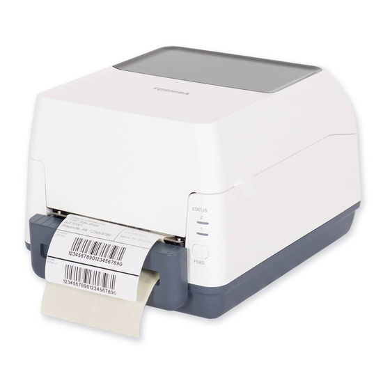
1 Introduction Toshiba B‐FV4T Owner’s Manual 1 Introduction Thank you for purchasing a Toshiba B‐FV4T printer. This manual provides information about how to set up and operate your printer, load the media and the ribbon, and solve common problems. 1.1 Features Various Connectivity Options USB, Ethernet, RS‐232C, Centronics Easy Operation One‐button design for easy control High Print Resolution 203 dpi for GS models, 300 dpi for TS models Fast Print Speed Max 6 inches/sec for GS models, max 4 inches/sec for TS ... -
Page 11: Unpacking
1 Introduction Toshiba B‐FV4T Owner’s Manual 1.2 Unpacking Make sure all of the following items are included in your package. When you receive the printer, open the package immediately and inspect for shipping damage. If you discover any damage, contact the shipping company and file a claim. Toshiba is not responsible for any damage incurred during shipping. Save all package materials for the shipping company to inspect. Note If any item is missing, please contact your local dealer. 2 ... -
Page 12: Understanding Your Printer
1 Introduction Toshiba B‐FV4T Owner’s Manual 1.3 Understanding Your Printer 1.3.1 Front View LED 2 LED 1 FEED Button 3 ... -
Page 13: Rear View
1 Introduction Toshiba B‐FV4T Owner’s Manual 1.3.2 Rear View Optional Interfaces 4 ... -
Page 14: Interior View I
1 Introduction Toshiba B‐FV4T Owner’s Manual 1.3.3 Interior View I 5 ... -
Page 15: Interior View Ii
1 Introduction Toshiba B‐FV4T Owner’s Manual 1.3.4 Interior View II 6 ... -
Page 16: Printer Lights
1 Introduction Toshiba B‐FV4T Owner’s Manual 1.4 Printer Lights 1.4.1 Status Lights Status lights can help you check printer’s condition. The following tables show the blinking speed of status lights and the conditions they indicate. Symbol Blinking Speed Blinking Interval Blinking Fast 0.5 Second Blinking 1 Second Blinking Slowly 2 Seconds LED 1 ... -
Page 17: System Mode
1 Introduction Toshiba B‐FV4T Owner’s Manual Red Red Cover (Thermal Head) open error. Red Red The RTC battery is low. (If the printer has a built‐in RTC) 1.4.2 System Mode The system mode consists of status light color combinations. It contains a list of commands for you to select and run. To enter the system mode and run the command, do the following: 1. Turn off the printer. 2. Press and hold the FEED button, and turn on the printer. 3. Both status lights will light up solid orange for a few seconds. Next, they turn to green shortly, and then turn to other colors. 4. When status lights show the color combination you need, release the FEED ... -
Page 18: Getting Started
2 Getting Started Toshiba B‐FV4T Owner’s Manual 2 Getting Started This chapter describes how to set up your printer. 2.1 Attaching Power 1. Make sure the power switch is set to the OFF position. 2. Insert the power supply’s connector into the printer power jack. 3. Insert the AC power cord into the power supply. 4. Plug the other end of the AC power cord into the wall socket. Warning Do not plug the AC power cord with wet hands, or operate the printer and the power supply in an area where they may get wet. Serious injury may result from these actions! 9 ... -
Page 19: Turning On/Off The Printer
2 Getting Started Toshiba B‐FV4T Owner’s Manual 2.2 Turning On/Off the Printer When the printer is connected to the host (the computer), it is good to turn on the printer before turning on the host, and turn off the host before turning off the printer. 2.2.1 Turn On the Printer 1. To turn on the printer, turn on the Power Switch as below. The “I” is the ON ... -
Page 20: Turn Off The Printer
2 Getting Started Toshiba B‐FV4T Owner’s Manual 2.2.2 Turn Off the Printer 1. Make sure LED 2 is off and LED 1 is solid green before turning off the printer. 2. To turn off the printer, turn off the Power Switch as below. The “O” is the OFF position. Warning Do not turn off the printer during data transmission. 2.3 Loading Media There are various types and sizes for the media roll. Load the applicable media to ... -
Page 21: Placing Media Roll
2 Getting Started Toshiba B‐FV4T Owner’s Manual between the printhead and platen roller. Inside Wound Outside Wound 2.3.2 Placing Media Roll 1. Open the top cover of the printer. 12 ... - Page 22 2 Getting Started Toshiba B‐FV4T Owner’s Manual 2. Press the switch lock on the Media Roll Holders to slide them outward, and place the media roll between the holders. Adjust the media roll so its print side is facing up, and make sure it is clamped tightly by the holders. 3. Push the Module Release Latch to open the printer module. 13 ...
- Page 23 2 Getting Started Toshiba B‐FV4T Owner’s Manual 4. Press the Lock button on the Media Guides to slide them outward. 5. Pull the media until it reaches out of the printer. 14 ...
- Page 24 2 Getting Started Toshiba B‐FV4T Owner’s Manual 6. Put the media under the Media Shaft and center it between the Media Guides. 7. Close the printer module and press down firmly at its both sides, until you hear a click. 15 ...
-
Page 25: Testing Media Feed
2 Getting Started Toshiba B‐FV4T Owner’s Manual 2.3.3 Testing Media Feed If you need to test the media feed, do this: 1. Turn on the printer, and press the FEED button to feed a label out of the printer. 2. To tear the media, pull the media gap against the Tear Bar. 16 ... -
Page 26: Media Types
2 Getting Started Toshiba B‐FV4T Owner’s Manual 2.3.4 Media Types Your printer supports various media types, including non‐continuous media, continuous media, and fanfold media. The following table provides details about them. Media Type Looks Like Description Non‐Continuous Non‐continuous media is the typical media for Media bar code printing. Labels and tags are made of various materials, such as paper, fabric or ... - Page 27 2 Getting Started Toshiba B‐FV4T Owner’s Manual Continuous Continuous media does not have gaps, holes, Media notches or black marks. It allows you to print data anywhere on the media. A cutter may be used for splitting labels. Mostly it is used for direct thermal printing. Fanfold Media Fanfold media is in continuous form, but it can be used as non‐continuous media, because its labels are separated by folds. Some fanfold media also has black marks or liners. Note If you are using thermal transfer mode, please continue to Section ...
-
Page 28: Loading Ribbon
2 Getting Started Toshiba B‐FV4T Owner’s Manual 2.4 Loading Ribbon Ribbons are only required for thermal transfer printing. You can use a wax, wax‐resin or resin ribbon. The type of the ribbon and the media should match to each other to get the proper print quality. The ribbon needs to be wider than or equal to the media to protect the printhead from wear. 2.4.1 Preparing Ribbon Remove the wrapping and the protective film of the ribbon. You will find two pairs of ribbon cores in the printer package. One of them is for 0.5‐inch inner diameter ribbon and the other is for 1‐inch. Install the applicable pair into the ribbon supply roll and take‐up roll. 19 ... -
Page 29: Placing Ribbon Roll
2 Getting Started Toshiba B‐FV4T Owner’s Manual 2.4.2 Placing Ribbon Roll 1. Open the top cover of the printer. 2. Push the Module Release Latch to open the printer module. 20 ... - Page 30 2 Getting Started Toshiba B‐FV4T Owner’s Manual 3. Lift the printer module to reveal the Supply Wheel. 4. Do the following to install both rolls: To load the supply roll, align the notches on the left side and press the roll to the supply hub, and then press the right side of the roll to the hole. 21 ...
- Page 31 2 Getting Started Toshiba B‐FV4T Owner’s Manual To load the take‐up roll, align the notches on the left side and press the roll to the take‐up hub, and then press the right side of the roll to the hole. 5. Pull the ribbon from the supply roll and tape it on the take‐up roll. 22 ...
- Page 32 2 Getting Started Toshiba B‐FV4T Owner’s Manual 6. Close the printer module and press down firmly at its both sides, until you hear a click. 7. Rotate the Take‐Up Wheel to straighten the ribbon and reduce its wrinkles. Note For the supply hub, the ribbon wind direction can be coated side in (CSI) or coated side out (CSO); for the take‐up hub, the wind direction must be CSO. 23 ...
-
Page 33: Printer Operation
Toshiba B‐FV4T Owner’s Manual 3 Printer Operation This chapter provides information about printer operation. 3.1 Media Sensor Calibration You will want the printer to work properly before starting your print jobs. To do this, you need to calibrate the media sensor. Toshiba B‐FV4T provides transmissive and reflective sensor calibration. Take the following steps to use them. 1. Make sure the media is properly loaded, the printer module is closed, and the printer’s power switch is set to the OFF position. 2. Press and hold the FEED button, and turn on the printer. ... -
Page 34: Self Test And Dump Mode
3 Printer Operations Toshiba B‐FV4T Owner’s Manual 3.2 Self Test and Dump Mode The printer can run a self test to print a configuration label, which helps you understand current settings of the printer. 3.2.1 Self Test 1. Turn off the printer. 2. Press and hold the FEED button, and turn on the printer. 3. Both status lights will light up solid orange for a few seconds. Next, they turn to green shortly, and then turn to other colors. When LED 1 turns to orange and LED 2 turns to green, release the FEED button. 4. Press the FEED button. The printer will print a configuration label. ... - Page 35 3 Printer Operations Toshiba B‐FV4T Owner’s Manual Your configuration label should look like this: 26 ...
-
Page 36: Dump Mode
3 Printer Operations Toshiba B‐FV4T Owner’s Manual 3.2.2 Dump Mode The printer will enter the Dump mode after running a self test. In this mode, characters are printed in hexadecimal codes, allowing users and engineers to debug the system. To return to the online mode: Turn off the printer, and turn it on again. 3.3 Restore Your Printer to Factory Settings Some problems can be solved by restoring the printer to its factory settings. Do the following to reset your printer. 1. Turn off the printer. 2. Press and hold the FEED button, and turn on the printer. 3. Both status lights will light up solid orange for a few seconds. Next, they turn to green shortly, and then turn to other colors. When both lights turn to red, release the FEED button immediately. ... -
Page 37: Media Sensing
3 Printer Operations Toshiba B‐FV4T Owner’s Manual 3.4 Media Sensing There are two media sensor types: transmissive and reflective. They are used for detecting specific media types. 3.4.1 Transmissive Sensor The transmissive sensor is fixed and placed near the center of the media path. It is used for detecting gaps across the entire width of the label. Single Column 28 ... -
Page 38: Reflective Sensor
3 Printer Operations Toshiba B‐FV4T Owner’s Manual 3.4.2 Reflective Sensor The reflective sensor is movable within the entire width of the media. It detects gaps, notches and black marks not located at the center of the media. Multi Columns Notch Black Mark Flip the media so the black‐mark side is facing down to align with the sensor. 29 ... -
Page 39: Maintenance
4 Maintenance Toshiba B‐FV4T Owner’s Manual 4 Maintenance This chapter describes routine cleaning procedure. 4.1 Cleaning To maintain print quality and prolong the printer’s life, you need to perform some routine maintenance. Daily maintenance should be done for high volume printing, and weekly for low volume printing. Warning Always turn off the printer before cleaning. ... -
Page 40: Media Housing
4 Maintenance Toshiba B‐FV4T Owner’s Manual printhead again. Note Printhead warranty becomes void if printhead’s serial number is removed, altered, defected, or made illegible, under every circumstance. 4.1.2 Media Housing Use a soft cloth to clean the dust, dirt or debris built up on the Media Roll Holders, Media Guides and media path. 1. Moisten a soft cloth with ethyl alcohol. 2. Wipe the Media Roll Holders to clean dust. 3. Wipe the Media Guides to clean dust and dirt. 4. Wipe the media path to clean paper debris. 31 ... -
Page 41: Sensor
4 Maintenance Toshiba B‐FV4T Owner’s Manual 4.1.3 Sensor Media sensors may not be able to detect the media correctly if it becomes dirty. 1. Moisten a soft cloth or a cotton swab with absolute ethyl alcohol. 2. Gently brush sensors to remove the dust away. 3. Use a dry cloth to clean the residue. 32 ... -
Page 42: Platen Roller
4 Maintenance Toshiba B‐FV4T Owner’s Manual 4.1.4 Platen Roller The platen roller is also important for print quality. Dirty platen roller may damage the printhead. Clean the platen roller right away if the adhesive, dirt or dust accumulates on it. 1. Moisten a soft cloth with absolute ethyl alcohol. 2. Gently wipe the platen roller to remove the dust and adhesive. ... -
Page 43: Replacing Rtc Battery
4 Maintenance Toshiba B‐FV4T Owner’s Manual 4.2 Replacing RTC Battery If your printer has a built‐in real‐time clock (RTC), you will find the RTC battery on the main board. The RTC battery keeps the RTC running when the printer is turned off, so the RTC can keep track of the current time. You can check the RTC battery charge from the status lights. If the RTC battery is low or out, you need to replace it with a new one. Take the following steps to replace your RTC battery: 1. Turn on the printer. 2. Locate the battery on the main board. 3. Remove the old coin battery and install a new one. 4. Turn off the printer. ... -
Page 44: Troubleshooting
5 Troubleshooting Toshiba B‐FV4T Owner’s Manual 5 Troubleshooting This chapter provides the information about printer problems and solutions. 5.1 Printer Problems The printer is not turned on Did you attach the AC power cord? Make sure the power supply’s connector is inserted into the printer power jack. Check the power connection from the wall socket to the printer. Test the power cord and the socket with other electrical devices. Disconnect the printer from the wall socket, and connect it again. The printer does not feed the media out The media is not loaded correctly. See Section 2.3, “Loading Media” to reload the media. If there is a paper jam, clear it. ... -
Page 45: Ribbon Problems
The printhead is dirty. Clean the printhead. The platen roller is dirty. Clean the platen roller. Adjust the print darkness, or lower the print speed. The media is incompatible for the ribbon. Use the compatible media instead. The media is incompatible for the printer. Use Toshiba‐approved media roll instead. 5.3 Ribbon Problems The ribbon is out Load a new ribbon roll. The ribbon is broken Check the print darkness and adjust it if it is too high, and take the following ... -
Page 46: Other Problems
5 Troubleshooting Toshiba B‐FV4T Owner’s Manual Unload the ribbon supply roll and take‐up roll from the printer. Pull the ribbon from the supply roll so it overlaps the broken end of the take‐up roll. Tape the overlapped parts together. Reload both rolls into the printer. The ribbon is “printed out” with the media The ribbon is not loaded correctly. See Section 2.4, “Loading Ribbon” to reload the ribbon. The printhead temperature is too high. Reload the ribbon and print a configuration label to check the settings (see Section 3.2, “Self Test and Dump mode”). If the print darkness is very high, adjust it in printer preference, or reset your printer (see Section 3.3, “Restore Your Printer to Factory Settings”). The ribbon is wrinkled 1. Make sure the ribbon is loaded correctly. 2. Rotate the Take‐Up Wheel to straighten the ribbon. 5.4 Other Problems There are broken lines in the printed label ... - Page 47 5 Troubleshooting Toshiba B‐FV4T Owner’s Manual Delete the files on your USB drive to free some space, or replace your USB drive with an empty one. The cutter is experiencing issues If there is a paper jam, clear it. The cutter has become loose. Fix the cutter in position and tighten it. The cutter blade is not sharp anymore. Replace your cutter with a new one. The printhead temperature is extremely high The printhead temperature is controlled by the printer. If it is extremely high, the printer will stop printing automatically, until the printhead is cool down. ...
-
Page 48: Specifications
B‐FV700‐BLTH‐QM‐R 6 Specifications This chapter provides specifications for the printer. 6.1 Printer Model B‐FV4T‐GS12‐QM‐R B‐FV4T‐GS12‐CN‐R B‐FV4T‐TS12‐QM‐R B‐FV4T‐TS12‐CN‐R Print method Direct Thermal and Thermal Transfer Resolution 203 dpi (8 dots/mm) 300 dpi (12 dots/mm) Media Alignment Centered Standard: Continuous mode, Tear‐off mode Operation Mode Optional: Cutter mode, Peeler mode Media Sensor: Gap Sensor (Transmissive, Fixed) I‐Mark Sensor (Reflective, Movable) Sensor Head Open Switch Ribbon Sensor 2, 3, 4, 5, 6 inches/sec 2, 3, 4 inches/sec Print Speed (50.8, 76.2, 101.6, 127, 152.4 mm/sec) (50.8, 76.2, 101.6 mm/sec) 2 &3ips for peel off mode 2 &3ips for peel off mode Darkness level: ‐10 ~ +10 Print Darkness Default: 0 Max Printable Area ... -
Page 49: Media And Ribbon
B‐FV700‐BLTH‐QM‐R 6.2 Media and Ribbon Properties Description Media Size Continuous Mode Length: 8 ~ 997 mm (including liner 10 ~ 999 mm) Width: 22.4 ~ 115 mm (including liner 25.4 ~ 118 mm) Tear‐Off Mode Length: 8 ~ 997 mm (including liner 10 ~ 999 mm) Width: 22.4 ~ 115 mm (including liner 25.4 ~ 118 mm) Peel‐Off Mode Length: 23.4 ~ 150.4 mm (including liner 25.4 ~ 152.4 mm) Width: 22.4 ~ 115 mm (including liner 25.4 ~ 118 mm) Cut Mode Length: 19.4 ~ 993 mm (including liner 25.4 ~ 999 mm) Width: 22.4 ~ 115 mm (including liner 25.4 ~ 118 mm) Max Roll Diameter Size: 127 mm (5 inches) Max Roll Diameter Size for External Media Stand: 216 mm (8.5 inches) Media Type Thermal Transfer Label Thermal Transfer Tag Direct Thermal Label Direct Thermal Tag ... -
Page 50: Bar Code
B‐FV700‐BLTH‐QM‐R 6.3 Bar Code Programming Language TPCL Non‐TPCL One Dimensional Bar JAN8/EAN8 UPC‐A Code JAN13/EAN13 UPC‐E UPC‐E JAN/EAN EAN13+2 digits CODE39 EAN13+5 digits CODE93 CODE128 (with auto code CODE128 selection) GS1‐128 (UCC/EAN128) CODE128 (without auto CODABAR (NW‐7) code selection) ITF CODE93 Industrial 2of5 UPC‐E+2 digits MSI UPC‐E+5 digits UPC add‐on code EAN8+2 digits POSTNET EAN8+5 digits GS1 DataBar UPC‐A Omnidirectional UPC‐A+2 digits ... - Page 51 B‐FV700‐BLTH‐QM‐R EAN‐13 GS1 DataBar Truncated EAN‐8 Composite (CC‐A/CC‐B) UCC/EAN‐128 with CC‐A GS1 DataBar Stacked or CC‐B Composite (CC‐A/CC‐B) UCC/EAN‐128 with CC‐C GS1 DataBar Expanded Stacked Composite (CC‐A/CC‐B) GS1 DataBar Expanded Composite (CC‐A/CC‐B) GS1 DataBar Stacked Omnidirectional Composite (CC‐A/CC‐B) GS1 DataBar Limited Composite (CC‐A/CC‐B) GS1‐128 Composite (CC‐A/CC‐B/CC‐C) ‐ 42 ‐ ...
-
Page 52: Electrical And Operating Environment
B‐FV700‐BLTH‐QM‐R 6.4 Electrical and Operating Environment Properties Range Power Supply Voltage: AC100 V ~ 240 V ±10 % (full range) Frequency: 50‐60 Hz ±5 % Power Consumption 90 W Temperature Operating: 5~40 °C Storage: ‐ 40 ~ 60 °C Humidity Operating: 25 ~ 85 %RH (non‐condensing) Storage: 10 ~ 90 %RH (non‐condensing) 6.5 Physical Dimension Dimension Size and Weight Size W 221 mm x D 279.3 mm x H 182.8 mm Weight 2.45 kg (excluding media and accessories) ‐ 43 ‐ ... -
Page 53: Interfaces
B‐FV700‐BLTH‐QM‐R 6.6 Interfaces This section provides information about IO port specifications for the printer. 6.6.1 USB There are two common USB connectors. Typically, type A is found on hosts and hubs; type B is found on devices and hubs. The figure below shows their pinouts. Type A Type B Pin Signal Description 1 VBUS +5V 2 D‐ Differential data signaling pair ‐ 3 D+ Differential data signaling pair + 4 Ground Ground ‐ 44 ‐ ... -
Page 54: Ethernet
B‐FV700‐BLTH‐QM‐R 6.6.2 Ethernet The Ethernet uses RJ‐45 cable, which is 8P8C (8‐Position 8‐Contact). The figure below shows its pinout. 1 2 3 4 5 6 7 8 Pin Signal 1 Transmit+ 2 Transmit‐ 3 Receive+ 4 Reserved 5 Reserved 6 Receive‐ 7 Reserved 8 Reserved ‐ 45 ‐ ... -
Page 55: Rs-232C
B‐FV700‐BLTH‐QM‐R 6.6.3 RS‐232C The RS‐232C on the printer is DB9 female. It transmits data bit by bit in asynchronous start‐stop mode. The figure below shows its pinout. Pin Signal Description 1 N/A Shorted to Pin 6 2 RxD Receive 3 TxD Transmit 4 N/A No Connection 5 GND Ground 6 N/A Shorted to Pin 1 7 RTS Request to Send 8 CTS Clear to Send 9 +5V Reserved for KDU (keyboard device unit) Note Pin 9 is reserved for KDU. Do not connect it if you are using a computer as the host. ... - Page 56 B‐FV700‐BLTH‐QM‐R Signal Signal Pin Signal Pin Signal Direction Direction 1 To Printer /STROBE 11 From Printer BUSY 2 To Printer Data 1 12 From Printer PE 3 To Printer Data 2 13 From Printer +5V 4 To Printer Data 3 14‐15 ‐ NC 5 To Printer Data 4 16‐17 Ground GND ...
- Page 57 B‐FV700‐BLTH‐QM‐R Installation Manual for the B‐FV704D‐BLTH‐QM‐R Bluetooth Interface WARNING! Carefully read and follow all the instructions in this manual. Failure to do so could create safety hazards such as fire or electric shocks. Instructions in this manual must be followed when installing option kits or adding cables to ...
- Page 58 B‐FV700‐BLTH‐QM‐R Bluetooth Interface (1 pc.) M‐3 P‐Tite Screw (2 pcs.) Installation Manual (1 copy) RF Certification Label ‐ 49 ‐ ...
- Page 59 6 Specifications Toshiba B‐FV4T Owner’s Manual 3. INSTALLATION PROCEDURE 1) Turn off the printer power, disconnect the power plug from the AC outlet, and disconnect the AC adapter from the printer. 2) Place the printer on the soft cloth to prevent scratching the surface of the printer, and remove the 4 screws provided at the Bottom Cover. 3) Remove the Bottom Cover by removing the 6 connectors from the main board. Connectors to be detached ...
- Page 60 6 Specifications Toshiba B‐FV4T Owner’s Manual 4) Remove the Printer Cover. Printer Cover 5) Secure the Bluetooth Interface with the 2 screws provided (M‐3 P‐Tite screws). Harnesses Note: When securing the interface, prevent the two harnesses from being trapped between the interface board and the printer frame.
- Page 61 6 Specifications Toshiba B‐FV4T Owner’s Manual 6) Attach the Printer Cover. Printer Cover Note: When fitting the Printer Cover, prevent the harness from being trapped between the covers. ‐ 52 ‐ ...
- Page 62 6 Specifications Toshiba B‐FV4T Owner’s Manual 7) Connect the harness connector to the connector “J15” (black) on the main board. Connector “J15” (black) 8) Return the 6 connectors to the original positions, which were removed in Step 3. 9) Fix the Bottom Cover by securing the 4 screws which were removed in Step 2.
- Page 63 Be sure not to cover the contents described on the rating label when the RF Certification Label is attached to the upper right corner. 11) Close the Top Cover. The installation is now completed. © 2015 TOSHIBA TEC CORPORATION All Rights Reserved 1‐11‐1, Osaki, Shinagawa‐ku, Tokyo 141‐8562, JAPAN PRINTED IN TAIWAN R141023P5200‐TTEC EO2‐38103 ...