Honeywell XNX Technical Manual
Universal transmitter
Hide thumbs
Also See for XNX:
- Quick start manual (100 pages) ,
- Technical manual (48 pages) ,
- Safety manual (15 pages)
Table of Contents
Table of Contents

Related Manuals for Honeywell XNX


Summary of Contents for Honeywell XNX
- Page 1 Technical Manual Universal Transmitter...
-
Page 3: Table Of Contents
XNX Universal Transmitter Table of Contents Safety 2�1 Mounting and Location of Sensors ����������������������������������28 Warnings ������������������������������������������������������������������������������5 2�1�1 Mounting the XNX Universal Transmitter � ��������������28 ® Cautions �������������������������������������������������������������������������������7 2�2 Wiring the XNX Transmitter � ����������������������������������������������30 Notes ������������������������������������������������������������������������������������7 2�2�1 General Wiring Considerations ��������������������������������30 Information � ��������������������������������������������������������������������������8 2�2�2 Distance Considerations for Installation �����������������31 1 Introduction 2�2�3 POD Connections �����������������������������������������������������36 1�1 Product Description ���������������������������������������������������������10 2�2�4 4-20mA Output, Common Connections, and Power Settings � �������������������������������������������������������������������������������37 1�1�1 The XNX Universal Transmitter � ������������������������������10 ® 2�2�5 Foundation Fieldbus Wiring ���������������������������������������38 1�1�2 20 mA/HART Output �����������������������������������������������11 ®... - Page 4 XNX Universal Transmitter Table of Contents 2�5 Configuring the XNX Universal Transmitter � ���������������������57 Transmitter Status ��������������������������������������������84 Select Language ������������������������������������������������57 Sensor Data �������������������������������������������������������85 Set Date & Time � ������������������������������������������������58 Sensor Status ����������������������������������������������������85 Set mV Sensor Type � ������������������������������������������59 Gas Data ��������������������������������������������������������������85 Set mA Sensor Type ������������������������������������������60 Range/Alarm Settings ���������������������������������������85 Range & Alarms �������������������������������������������������67 mA Level Settings � ���������������������������������������������86 Latching / Non-Latching �����������������������������������69 Fieldbus Settings � ���������������������������������������������86 Set Units ��������������������������������������������������������������70 Relay Data ���������������������������������������������������������86 mA Levels ����������������������������������������������������������70 Event History � ���������������������������������������������������87 Calibration Interval ��������������������������������������������71 3 Calibration Accept New Sensor Type � ����������������������������������72 3�1 Gas Calibration Menu ���������������������������������������������������90...
- Page 5 XNX Universal Transmitter Table of Contents 4 Maintenance 6�4�2 XNX EC Replacement Sensors ������������������������������152 4�1 MPD Sensor Cartridge Replacement �����������������������������104 6�4�3 XNX EC Replacement Cells �����������������������������������153 4�2 XNX EC Sensor Cartridge Replacement � ����������������������105 6�4�4 Multi Purpose Detector (MPD) �������������������������������154 ® 4�2�1 Replacing with the Same Cartridge Type ��������������105 6�4�5 XNX Catalytic Bead and IR Replacement Sensor Cartridges ������������������������������������������������������������������������154 4�2�2 Replacing with a Different Cartridge Type � ������������106 6�4�6 Accessories/Spares � �����������������������������������������������155 5 Warnings and Faults 7 Control Drawings 5�1 Warning Messages ����������������������������������������������������������108 7�1 XNX UL/INMETRO �����������������������������������������������������������160 5�2 Fault Messages ���������������������������������������������������������������113 7�2 XNX UL/CSA/FM � �������������������������������������������������������������163 5�3 Informational Messages � �������������������������������������������������124 7�3 Remote Sensor Mount ���������������������������������������������������166 6 Specifications Appendix A - HART Protocol ®...
- Page 6 XNX Universal Transmitter Table of Contents Table of Contents...
-
Page 7: Warnings ������������������������������������������������������������������������������5 2�1�1 Mounting The Xnx ® Universal Transmitter
XNX Universal Transmitter • The sensor must be earthed/grounded for Intrinsic Safety, electrical Safety safety and to limit the effects of radio frequency interference. Earth/ Read and understand this manual before installing, operating, or ground points are provided inside and outside the unit. EMI note maintaining the XNX Transmitter� Pay particular attention to the for applications using shielded cable: Cable shield terminations warnings and cautions below� All of the warnings and cautions must be made at the cable glands with suitable EMI type glands. shown here are repeated in the appropriate sections of the Avoid terminating cable shields at the Earth ground lug inside the manual � XNX enclosure. In cases where wiring is in pipe, a shielded cable is not required. The external terminal is only a supplemental bonding connection where local authorities permit or require such a connection. • Take care when handling EC sensor cells as they may contain corrosive solutions. Warnings: Identify hazardous or unsafe practices which could result in severe injury or death. • Do not tamper or in any way disassemble the sensor cells. • Do not expose to temperatures outside the recommended range. • Do not expose the sensor to organic solvents or flammable liquids. Warnings • At the end of their working lives, sensors must be disposed of in • Installation must be in accordance with the recognized standards of the an environmentally safe manner, in accordance with local waste appropriate authority in the country concerned. management requirements and environmental legislation. Do NOT • Access to the interior of the sensor, when carrying out any work, must... - Page 8 XNX Universal Transmitter • Keep the passwords in a secure area to prevent unauthorized access • When the transmitter is equipped with the optional Remote Mount Kit, the remote sensor must be securely mounted in a fixed position. The to the transmitter. If the passwords are lost, resetting the XNX Remote Sensor kit is not intended to be used as a hand-held sensor. transmitter will require a service technician. • Enclosures of remotely mounted sensors contain aluminum. Be careful • When the XNX transmitter is placed in Inhibit Mode, alarms are to avoid ignition hazards due to impact or friction when installed in silenced. This will prevent an actual gas event from being reported. Zone 1 locations. Inhibit Mode must be limited to testing and maintenance only. Exit Inhibit Mode after testing or maintenance activities. • Install the junction box according to local codes and manufacturer’s requirements. • Honeywell recommends periodic bump tests (every 30 days or in accordance with customer site procedures) to the sensor to insure • The enclosures of remotely mounted 705HT sensors contain proper operation and compliance with the functional safety rating of aluminum. Be careful to avoid ignition hazards due to impact or friction the installation. when installed in Zone 1 locations. • As some test gases are hazardous, exhaust the flow housing outlet to a • Power off the transmitter before changing S3 or S4. Both switches safe area. Do not use the XNX Universal Transmitter in oxygen-enriched must be set in either Source or Sink prior to applying power. atmospheres. (In oxygen-enriched atmospheres, the electrical safety is • Minimum and maximum controller alarm levels should not be set not given.)
-
Page 9: Cautions
XNX Universal Transmitter • Special Conditions for Safe Use • The options “Modbus interface” and “Foundation Fieldbus interface” are not subject of this EC-type examination certificate. • The following applies to the HART Barrier intrinsically safe circuits: For installations in which both the Ci and Li of the intrinsically • Long-term exposure (> 20 minutes) to concentrations exceeding the safe apparatus exceeds 1% of the Co and Lo parameters of the fullscale range of the H2S sensor type 2 can cause it to lose sensitivity. associated apparatus (excluding the cable), then 50% of Co and The measured value may decrease even though high levels of toxic Lo parameters are applicable and shall not be exceeded, i.e. the Ci gas are still present. If such conditions can occur, set the control unit of the device plus the C of the cable must be less than or equal to to latch at overrange. In standalone operation, set alarms to latching. 50% of the Co of the associated apparatus, and the Li of the device plus the L of the cable must be less than or equal to 50% of the Lo When resetting the overrange or alarm, verify correct operation of the of the associated apparatus. transmitter. • For circuits connected to the EC barrier in which the capacitance Hazardous Location Installation Requirements and inductance exceed 1% of the permitted values, then the maximum permitted capacitance is limited to 600nF for group IIC (UL/CSA) and 1uF for group IIIC. -
Page 10: Information � ��������������������������������������������������������������������������8 2�2�2 Distance Considerations For Installation
XNX Universal Transmitter Information Honeywell Analytics assumes no responsibility for equipment that is not installed and used following the procedures in the Technical Manual� The reader of this manual should ensure that the appropriate equipment has been installed� If in doubt, contact Honeywell Analytics� Every effort has been made to ensure the accuracy of our documents, however, Honeywell Analytics can assume no responsibility for any errors or omissions in its documents or their consequences� Honeywell Analytics greatly appreciates being informed of any errors or omissions that may be found in the contents of any of its documents� For information not covered in this document, or if there is a requirement to send comments/corrections about this document, please contact Honeywell Analytics using the contact details given on the back cover of this document� Honeywell Analytics reserves the right to change or revise the information supplied in this document without notice and without obligation to notify any person or organization of such revision or change� If information is required that does not appear in this document, contact the local distributor/agent or Honeywell Analytics� is a registered trademark of Honeywell International� ® HART is a registered trademark of the HART Communication ® Foundation� Modbus is a registered trademark of Schneider Automation Inc� ® FOUNDATION is a trademark of Fieldbus Foundation� Introduction... -
Page 11: Introduction
XNX Universal Transmitter 1 Introduction XNX Universal Transmitter Technical Manual... -
Page 12: 1�1 Product Description
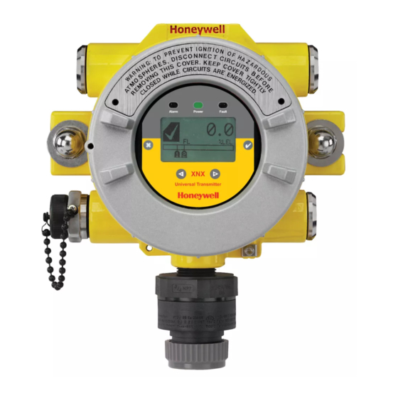
Figure 1� Electrochemical sensors, with Hot Swap, pre-calibrated XNX EC Toxic and O Sensing through Intrinsically Safe (IS) barrier The XNX Universal Transmitter also allows for an optional � There are three main types of gas hazards: flammable, toxic, and asphyxiant� A flam- Figure 1. XNX Universal Transmitter and supported sensing technologies mable gas hazard is one in which there is a risk of fire and/or explosion (e�g�, a situation The XNX Universal Transmitter relies on 4-20mA output, refreshed in which a gas such as methane, butane, or propane is present)� A toxic gas hazard is one in which there is a risk of poisoning (e�g�, a gas such as carbon monoxide, hydrogen at least every two seconds (once per second is typical), in which sulfide, or chlorine is present)� An asphyxiant hazard would include a risk of suffocation the output is proportional to the gas concentration� through oxygen deficiency� (Oxygen can be consumed or displaced by another gas�) Section 1 - Introduction... -
Page 13: 1�1�2 20 Ma/Hart ® Output
XNX Universal Transmitter 1.1.2 20 mA/HART Output ® The transmitter uses HART over 4-20mA as the standard communications protocol� Additional optional communication All XNX Transmitters provide a 20mA Current Loop with HART interfaces are available: relay communication, Modbus, or Digital Communication which can be user configured for Sink, Foundation Fieldbus� Each communication option has a Source (3-Wire) or Isolated (4-Wire) electrical interface based on dedicated option board� For additional information, refer to installation requirements� Section 1�3 Options� The 20mA current loop output provides an analog indication 1.1.4 Certifications of special states, a proportional output to gas concentration and over range indication per the table below� In the event of XNX-UT**-****** Versions are UL classified and CSA listed for a simultaneous alarm and fault, an alarm condition will always installation in Class I, Division 1, Groups B, C and D Hazardous override a warning state� Locations� FM Approvals evaluation includes Class I, Zone 1, Groups B, C, D, as well as performance tests for specific Output Description* Notes sensor/transmitter combinations� CSA/FM certification does not cover daisy-chained XNX combustible gas transmitters, the 1�0 mA Fault use of HART, Modbus, or Foundation Fieldbus protocols for Special Warm-up combustible gas performance� HART, Modbus, or Foundation... -
Page 14: 1�1�5 Patents
XNX Universal Transmitter 1.1.5 Patents 1.2.1 Enclosure This table shows details about XNX-related patents� Available in either Stainless Steel or Aluminum, with 3/4” NPT (UL/CSA or UL/ INMETRO) or M25 (ATEX/IECEx only) threaded Patents Applicable to the XNX Universal Transmitter cable/conduit ports, the XNX Universal Transmitter enclosure is explosion-proof and suitable for use in -40°F to +149°F (-40°C to Patent Description Application Number +65°C) operating conditions� A 5-coat marine finishing process provides the highest degree of corrosion protection� For more 6,123,818 Reflex patent Implemented in XNX information on performance specifications, see Section 6 - 6,251,232 Reflex patent Implemented in XNX Specifications� 6,351,982 Flammable sensor housing XNX accepts this sensor The XNX enclosure is equipped with five threaded cable/conduit 6,395,230 Pellistor Sensor used in XNX... -
Page 15: 1�2�2 Cover �������������������������������������������������������������������������13 2�2�9 Ir Personality Wiring
A locking screw integrated into the cover provides positive Searchpoint Optima Plus A or E locking that can be removed by using the supplied 2mm hex Searchline Excel Typically C � Remote Sensor Connection (except EC ) Any remaining Searchpoint Optima Plus - Remote Any remaining Modbus Any remaining Relays Any remaining Figure 4. Magnetic Wand/Screwdriver Power Any remaining Figure 5. XNX Universal Transmitter Cable/Conduit Port Assignments Note: When attaching the cover or stopping plugs, coat the threads to prevent corrosion. See the XNX Universal Transmitter Parts List (document 1998-0807) for a de- scription of all of the parts that are shipped with the transmitter� Section 1 - Introduction... -
Page 16: 1�2�3 Pod
For more information, see Appendix A - HART Protocol� via a slot in the POD housing� The optional communication boards vary depending on the option selected when ordered� Only one of the three available interface options (relays, Modbus, or Foundation Fieldbus) can be attached to the XNX transmitter� Figure 7. XNX Universal Transmitter with HART Interface IS Barrier 1.3.2 Relays The relay option (XNX-Relay) provides 3 form “C” (SPDT) normally open/normally closed (NO/NC) contacts for alarm and fault indication� A remote reset input is provided (TB4)� Momentarily closing the the circuit between the pins of TB4 performs the same function as the Reset Alarms & Faults command� The XNX transmitter has three relays: relay 1 is for alarm level Figure 6. POD, exploded View 1, relay 2 is for alarm level 2, and relay 3 is for faults and special Section 1 - Introduction... -
Page 17: 1�3�3 Modbus
The maximum refresh rate of the relays is 2 seconds� See Set pipe mount bracket, two carriage bolts, nuts, and lock washers� Alarm Values for more information� 1.3.3 Modbus The optional Modbus interface allows the XNX to connect to a bus of devices and transmit data to PLCs or controllers� (For more information, see the Modbus Protocol Manual)� Connections to the XNX are made through a pluggable terminal block on the Modbus interface circuit board� Modbus RTU protocol uses ASCII/Hex protocols for communication� Figure 8. Pipe-mounted XNX Transmitters Note: POD options are either relay, Modbus, or Foundation Fieldbus. Calibration Gas Flow Adapter The calibration gas flow adapter is used to apply calibration test gas to the sensor� It attaches to the bottom of the sensor and can be fitted without removing the weatherproof cover� See 1.3.4 Foundation Fieldbus Section 3 - Calibration for further details on gas calibration� Foundation Fieldbus is a digital communication system which Sensor Flow Adapter P/N supports several types of messages� Unlike many traditional systems which require a set of wires for each device, multiple XNX EC... - Page 18 XNX EC Included stainless steel ceiling mount brackets, bolts, 02000A1640 and nuts� Sensepoint 02000-A-1640 00780-A-2076 Remote Gassing Kit MPD-*TCB1 SPXCDWP (included) The Remote Gassing Kit (1226A0354) enables gas to be Remote Sensor Mounting Kit for XNX EC Sensors applied remotely for performing The remote sensor mounting kit functional response checks (bump (S3KRMK) allows XNX EC sensors to tests)� The kit Includes: 50’ Teflon ® be remotely mounted via an IS cable tubing, a mounting bracket, a tube kit, up to 50 feet (15 meters) from the cap, and device adapters in 1/4” transmitter� The kit includes 50 feet of and 1/8” (6�3 mm and 3�2 mm) ID to shielded cable, cable glands, and attach to bump test ports on the remote terminal box� The cable can be...
-
Page 19: 1�4 The Xnx Front Panel ���������������������������������������������������������17 2�3�4 Foundation Fieldbus
XNX Universal Transmitter 1.4 The XNX Front Panel Weather Protector The Extreme Weather Protector (SPXCDWP) is The XNX Transmitter uses magnetic switches to enable non- designed to protect the sensor from intrusive operation� To activate a magnetic switch, hold the environmental conditions in outdoor exposure magnetic end of the screwdriver up to the glass window and applications� slowly swipe the magnet directly over the shaded area� For best results, hold the screwdriver as illustrated in Figure 9� Switch Actuation Visual Indicator Enter/Accept Escape/Back Move Right/Increment Value Move Left/Decrement Value Figure 9. Using the magnetic wand A decal illustrating the proper method for actuating the magnetic switches is placed on the POD of each transmitter� Section 1 - Introduction... -
Page 20: 1�4�1 Controls And Navigation
Alarm LED (red) Escape Enter/Accept Switch Actuation Visual Indicator Move Left Decement Value Move Right Increment Value Figure 11. Front panel display of the XNX transmitter Figure 10. Operation decal 1.4.1 Controls and Navigation The switch is actuated by the flux lines between the poles of the Command Description magnet� This actuation method provides the most consistent response� The Enter/Accept switch is used to access menus, ✓... - Page 21 XNX Universal Transmitter 1.4.2 The General Status Screen When a warning is triggered, the warning icon appears and information is displayed on the General Status Screen� The information displayed alternates between screens displaying the gas concentration and the warning code� See Section 5 - Warnings/Faults for more warning code information� Warning Code Warning Icon Figure 12. General Status screen The General Status Screen shows the status of the XNX Transmitter� Figure 14. General Status Warning detail Current Concentration Level If the Fault icon is displayed, a fault condition has been (Numeric) triggered and the display will alternate between the target gas Status Indicator Concentration Units concentration and the fault code� See Section 5 - Warnings/...
- Page 22 XNX Universal Transmitter 1.4.3 Entering the Menu Structure Alarm Level Triggered Alarm Icon Swiping the magnet over the magnetic switch or allows the ✓ ✖ user to reset faults or alarms, display current settings, or make Target Gas adjustments to the device� Concentration Figure 16. General Status Alarm detail Note: If the Easy Reset option is set to Lock, alarms and faults In an over range condition, the alarm icon will display and the target gas cannot be reset without logging in or entering a passcode. For more concentration bar graph and alarm setpoints will flash� information, see Section 2.5.1 Configure Security. Alarm Level Triggered Full Scale Swiping the or “escape” magnetic switch activates the Alarm...
- Page 23 XNX Universal Transmitter Figure 21. Invalid Passcode screen Figure 19. Passcode screen 1.4.4 Displaying Transmitter Information Warning: The factory-set passcodes must be reset to prevent While in the General Status display, swipe the magnet over the unauthorized access to the transmitter’s menus. magnetic switch to display information about the transmitter� The General Status display will replace the bar graph in the lower portion of the screen with the unit’s serial number, the When the Passcode Screen is displayed, the first passcode date and time, and the unit’s part number� digit is highlighted� Use the switches to increment or decrement through the values� Once the correct value is displayed for the first digit, accepts the value and moves to ✓ the next digit or moves to the previous digit of the passcode� ✖ Figure 22. General Status Screen with Unit Information ✓...
-
Page 24: 1�5 Main Menu �������������������������������������������������������������������������22 (Except Searchline Excel)
XNX Universal Transmitter 1.5 Main Menu Once the proper passcode has been entered, the transmitter displays the Main Menu� Figure 23. The Main Menu From the Main Menu, a Level 1 user can: • display the current settings/configuration • test the transmitter • calibrate and bump test the transmitter • configure the unit for language, date and time The Main Menu consists of these options: Menu Description Section... Provides access to settings to configure the Configure 2.5.1 transmitter and connected devices Provides access to tools and settings to allow Test 2.6.1 simulation of gas events to test the system Displays current settings for the XNX transmitter Information 2.6.2 including optional relays and Modbus Displays the XNX interface to calibrate sensors Calibration attached directly to the transmitter Section 1 - Introduction... -
Page 25: 1�5�1 Xnx Menu Map
XNX Universal Transmitter 1.5.1 XNX Menu Map Status Display Main Menu Alarm/Fault Reset Passcode Display Display 4. Configuration Mode 1. Information Mode 2. Test Mode 3. Calibration Mode Continued Continued Continued Continued on page 24 on page 25 on page 25... - Page 26 XNX Universal Transmitter Fieldbus Settings Fieldbus Settings Event History Increment Next/Previous Event Information Mode Increment Next/Previous Hour Alarm/Fault Status Increment Next/Previous Day Alarm/Fault Increment Next/Previous Alarm Confirm Alarm/Fault Reset Increment Next Previous Fault Reset Alarm/Fault Date & Time Transmitter ID, Serial #, Revision Transmitter Data Transmitter Status Transmitter Status Sensor Type, Serial #, Revision Sensor Data Sensor Status Sensor Status Gas Name, ID, Range Gas Data Range Settings, Alarm Settings Range/Alarm Settings mA Level Settings mA Level Settings Relay Settings Relay Settings 6 Optional Foundation Fieldbus and Modbus only 5 Optional relay only Section 1 - Introduction...
- Page 27 XNX Universal Transmitter Test Mode Calibration Mode Inhibit Gas Calibration Enable/Disable Inhibit Enter Span Gas Concentration (Oxygen) Force mA Output Enter Span Gas Concentration (Not Oxygen) Select Current: 0 to 22 mA Bump Test Accept mA Output Calibration Force Relay Adjust 4 mA Output Select Relay 1 Adjust 20 mA Output Select Relay 2 Soft Reset Align Excel Select Relay 3 Accept Alarm/Fault Simulation Alarm 1 Simulation Alarm 2 Simulation Warning Simulation Fault Simulation 8 Searchpoint Optima and Searchline Excel only 9 Searchline Excel only 7 Optional relay only Section 1 - Introduction...
- Page 28 XNX Universal Transmitter Change mA for Warning Change mA for Overrange Change mA for Low Signal Change mA for Blocked Beam Set Calibration Interval Configuration Mode Accept New Sensor Type Select Language Information screen identifying previous sensor and Set Date & Time new sensor Set Date Format Screen displays new type and old type Set Year, Month, Day Set Beam Block Set Hours, Minutes, Seconds Select Beam Block Threshold Sensor Type Selection Select Time to Beam Block Set mV Sensor Type Select Time to Fault Set mA Sensor Type Set Path Length Gas Selection Set New Path Length Changing the Gas or Units Name Configure Unit ID Gas Selections and Alarm Limits Based on mV Edit ID Sensor Type Clear ID Range & Alarms Default ID Set Range Relay Options Alarm 1 Type...
- Page 29 XNX Universal Transmitter 2 Installation and Operation XNX Universal Transmitter Technical Manual...
-
Page 30: Safety 2�1 Mounting And Location Of Sensors
• ease of access for functional testing and servicing • how escaping gas may behave due to natural or forced air currents� 2.1.1 Mounting the XNX Universal Transmitter ® The transmitter can be mounted in a number of ways using the integral mounting tabs� The transmitter can be attached to flat wall surfaces or to Unistrut � With the optional Pipe Mount kit, ® the unit can be mounted to pipe of diameter 2” to 6” (50 to 150mm)� A ceiling mount bracket kit (1226A0358) is also available� Note: Agency certifications require that EC and mV sensors face down. Optima sensors must be mounted horizontally. Figure 24. XNX Universal Transmitter mounting dimensions and clearances Section 2 - Installation and Operation... - Page 31 Local HART ® Option XNX Electrochemical Sensor - Local/Remote MPD, 705 Series, Sensepoint Series Searchpoint Optima Plus A or E Searchline Excel Typically C Figure 27. Optional pipe and ceiling mounts Remote Sensor Connection (except EC ) Any remaining Searchpoint Optima Plus - Remote Any remaining Modbus Any remaining Relays Any remaining Power Any remaining Figure 25. XNX Universal Transmitter cable/conduit port assignments Section 2 - Installation and Operation...
-
Page 32: 2�2 Wiring The Xnx Transmitter
XNX Universal Transmitter 2.2 Wiring the XNX Transmitter Caution: Before wiring the transmitter, confirm that the correct The XNX transmitter is available in sensor technologies, or personality and communication boards are installed. personality options, which support a variety of sensors and applications� Each of the personalities use dedicated interface boards� Pluggable terminal blocks are used for easy connection 2.2.1 General Wiring Considerations and service� The personality boards and optional communication interfaces are enclosed in plastic housings comprising the For proper operation of the XNX Universal Transmitter and electronics POD (Personality, Options, and Display)� The sensor technologies, consideration of wiring-induced voltage Personality circuit board determines the XNX behavior based on drops, transient electrical noise, and dissimilar earth ground the sensor type attached to the XNX interface (Figure 35)� See potentials is imperative in the design and installation of the Specifications for drift and zero deviation values� system� This table illustrates the three XNX transmitter configurations EMI note for applications using shielded cable: Cable and the sensors each support�... - Page 33 XNX Universal Transmitter is 16 to 32 VDC for EC and mV versions, 18 to 32 VDC for Single Transmitter Searchpoint Optima Plus and Searchline Excel, and 16 to 32 This is the simplest type of installation� It consists of a single VDC depending on the limitations of the device for the generic XNX transmitter installation per power source� 4-20mA input� Loads The use of high inrush or inductive loads may affect the performance of the transmitter� For best reliability use resistive Class 2 Class 2 Class 2 loads only� Power Supply Power Supply Power Supply Figure 29. Single Transmitter Installation 2.2.2 Distance Considerations for Installation Advantages: • Maximum distance between power source and transmitter Providing power to the transmitter is the factor that will • Smaller power source...
- Page 34 The nominal voltage for all XNX transmitters is 24V with the Disadvantages: power required depending on the number of points using the • Larger power source will be needed same power supply� • If a power source fails, several monitoring points fail� Multiple Transmitters Connected in a “Daisy-Chain” Configuration XNX Universal Transmitter Maximum Power Consumption This configuration consists of two or more transmitters installed -40°C to +65°C -10°C to +65°C in a line� The power connections are installed as an extension of HART over 4-20mA HART HART over 4-20mA HART the previous transmitter, with the first transmitter being the only...
- Page 35 XNX Universal Transmitter Searchpoint Optima Plus (10 watts)� A 25 watt power supply Single Transmitter Distances would probably handle this installation, but a 30 watt power 18 AWG 16 AWG 14 AWG 12 AWG supply would be a better choice� Configuration [1.0 mm2] [1.5 mm2] [2.0 mm2] [3.5 mm2] 4620 feet XNX mV or EC 1140 feet 1810 feet 2890 feet Wire Selection [1408 With Sensor [347 meters] [551 meters] [880 meters] meters] The type of wire used for connections has an effect on the distance of the installation� This is because some of the voltage...
- Page 36 XNX Universal Transmitter Daisy-Chained Transmitter Distances 3 Transmitters - Distance “d” It is difficult to calculate distances for this configuration� There 18 AWG 16 AWG 14 AWG 12 AWG Configuration are many factors to be considered: distance from control room [1.0 mm2] [1.5 mm2] [2.0 mm2] [3.5 mm2] to first transmitter, distance between transmitters, sensor types, XNX mV or EC 190 feet 300 feet 480 feet 770 feet etc� A few scenarios are presented here to provide a base to With Sensor [58 meters] [91 meters]...
- Page 37 XNX Universal Transmitter 2� Several transmitters installed in pairs with each pair 6 Transmitters - Distance “d” equally spaced from the next pair and the power source� 18 AWG 16 AWG 14 AWG 12 AWG These distances assume the paired transmitters are Configuration [1.0 mm2] [1.5 mm2] [2.0 mm2] [3.5 mm2] installed within 10 feet [3 meters] of each other� XNX mV or EC 95 feet 150 feet 240 feet 385 feet Transmitters 1 and 2 Transmitters 3 and 4...
-
Page 38: 2�2�3 Pod Connections
Source EC Personality EC IS Barrier IR 4-20mA Personality Input Sink IR Personality Com A and B Table E Table F Figure 35. XNX Personality Board Terminal Block Legend Board Type Connection Function Board Type Connection Function Each of the personalities use a single terminal block for Remote Reset Relay Relay Relay Output Connector connection with the exception of the IR personality, which requires a second terminal block�... -
Page 39: Settings
Signal Mode Current Source Down Flow Sink Down XNX Sink Configuration Isolated Down Down Figure 36. Sink wiring for XNX Most controllers in the market will accept source-configured Terminate cable screen at the detector or controller, not both. Controller devices� Sink-configured signals are used in older technology controllers, which reduce the need for complete system upgrades�In isolated-signal devices, if the controller fails or the Signal mA signal wires are disconnected or broken, the field device will remain operational� Most controllers in the market will accept Current Flow isolated configured devices�... -
Page 40: 2�2�5 Foundation Fieldbus Wiring
TB-3 Modbus to internal ground lug TB-3 SW5 - Sim switch Use shorting jumper supplied to maintain connection during service Jumper assignments Internal ground lug Figure 39. XNX Foundation Fieldbus option board and terminal block Section 2 - Installation and Operation... -
Page 41: 2�2�7 Ec Personality Wiring
Sink ▼ -mA 1-6 ▼ ▼ Isolated TB-1 J2 - EC Barrier Connector Position EC Barrier XNX EC TB-1 Figure 41. XNX EC Personality Board Terminal Blocks and Jumper Switches and Terminal Block Assignments Section 2 - Installation and Operation... -
Page 42: Xnx Electrochemical Sensor Installation
XNX Universal Transmitter XNX Electrochemical Sensor Installation Optional Local HART IS Barrier must be connected to J1 S1 S2 J1 HART EC Sensor Installation J2 EC Barrier EC IS Barrier must Caution: A missing oxygen cell will result in 0% V/V O gas be connected to J2 concentration, thus triggering alarm events. In this situation, check the connection of the EC cell to the sensor connector board. -
Page 43: Xnx Ec Sensor Remote Mounting Kit
XNX Universal Transmitter 6� After the sensor is installed and the gas type is confirmed, the range, alarm levels, and other important settings must Note: Reference Control Drawing 3000E3157 and 3000E3159 for be set; see Section 2�5� install requirements on EC cells and remote mounting. 7� After the transmitter has been configured, calibrate the sensor following the procedures in Section 3 - Calibrations� XNX EC Sensor Remote Mounting Kit The remote sensor mounting kit is used to mount the XNX EC sensor up to 50 feet away from the transmitter� To mount the sensor remotely, follow this procedure: 1� Unscrew the weatherproof cover, loosen the retainer locking screw and unscrew the sensor retainer� 2� Remove the sensor by pulling without twisting� 3� Plug the remote sensor cable connector into the bottom of the transmitter� 4� Route the cable to the location where the remote sensor is Transmitter to be mounted� New Sensor 5� Optional: make a loop of cable at the junction box� This will provide some slack for any future re-terminations� 6� If necessary, cut the cable to the required length�... - Page 44 XNX Universal Transmitter 7� Mount the remote sensor junction box ensuring enough room below to fit the sensor and weatherproof cover� See control drawing 3000E3157 in Section 7�2 for specific mounting information� 8� Attach the cable to the remote terminal box via the gland provided� 9� Make the wiring connections as shown in Figure 43� 10� Fit the Terminal box lid� 11� Plug the sensor into the socket at the bottom of the terminal box� 12� Fit the sensor retainer, tighten the locking screw, and fit the weatherproof cover� 13� Calibrate the sensor following the procedure in Section 3�2�1� Connections Pin # Color Yellow Sensor Cartridge Green Blue White Sensor Retainer Black Weatherproof Cap Sensor Mounted to Remote Sensor Kit Figure 44.
-
Page 45: 2�2�8 Mv Personality Wiring
XNX Universal Transmitter 2.2.8 mV Personality Wiring Caution: Do not force the POD into the enclosure. Doing so may XNX Universal Transmitter with the mV personality Board allows result in damage to the wiring or the POD or may alter the switch interface to HA’s Multi Purpose Detector (MPD) and field proven settings. If resistance is felt, wires may be preventing the POD from 705 and Sensepoint devices� being properly positioned. Caution: Be certain to dress the wires properly to ensure cabling Caution: See Section 6 - Specifications to ensure that the does not contact switches 1-2 on the back of the POD. transmitter and the mV sensor have the appropriate approvals prior to commissioning. Caution: Verify that the mV sensor being installed has compatible threads (3/4 NPT or M25). Read Section 2�2 which defines the XNX power and 4-20mA output connections that are common to all personalities� Connections from the mV Sensor to the XNX are made via a single pluggable terminal block allowing ease of installation and service� Honeywell Analytics recommends that an 8” (203 mm) service length for wiring be maintained� The wire colors for the connections for each sensor type are shown in the following Wire Color from Sensor table� Verify that wires for 4-20mA outputs are routed away from sources of noise such as relay wires� Note: The black and red wires from the MPD are not used with the XNX mV personality board. Ensure that they are properly isolated from live connections. Do NOT cut the wires. Section 2 - Installation and Operation... - Page 46 XNX Universal Transmitter J1 - Local HART Option Connector internal Optional Local HART grounding lugs IS Barrier must S1 and S2 - 20mA Output S1 S2 Jumper Switch J1 HART be connected to J1 ▼ ▲ Source LOCAL HART Sink ▲...
- Page 47 XNX Universal Transmitter mV Remote Sensor Mounting 3� Wire the pluggable terminal block as shown in Figure 45 then plug the connector into the back of the mV The sensor can be mounted remotely from the transmitter; the installation will vary by installed location, sensor and thread type personality board� In remote mount MPD configurations, used� To remotely mount the sensor, follow this procedure: the 3 wires connecting the pluggable terminal block and 1� Unscrew the transmitter’s weatherproof cover and loosen the remote MPD must be routed through the supplied the retainer locking screw with the supplied hex key� ferrite bead (Honeywell Analytics part no� 0060-1051, 2� Run conduit from one of the transmitter’s available conduit supplied in the accessory kit) as shown in Figure 48� ports to the location of the remote terminal housing� Internal Ground Lug A terminal housing provides a mounting base for the (do not use) sensor� The installation wiring enters the terminal housing via conduit� Power UL/CSA Aluminum Junction Box UL/CSA Stainless Steel Junction Box...
-
Page 48: Searchline Excel
XNX Universal Transmitter 5� Attach the conduit to the remote terminal box� communication line as long as it is in agreement with the 4-20 mA output, otherwise the 4-20mA output takes precedence� 6� In the remote junction box, connect the wires from the transmitter to the 3-way terminal block in the terminal box� Caution: Dress the wires properly so that cabling does not contact switches 1-4 on the back of the POD. Note: The black and red wires from the MPD are not used with the XNX mV personality board. Ensure that they are properly isolated from live connections. Do NOT cut the wires. The transmitter provides a 4-20mA output reflecting the input received� It also offers diagnostic information or data via HART or any of the additional communication options offered� Warning: The enclosures of remotely mounted 705HT sensors Read Section 2�2 which defines the XNX power and 4-20mA contain aluminum. Be careful to avoid ignition hazards due to impact output connections that are common to all personalities� or friction when installed in Zone 1 locations. Warning: Power off the transmitter before changing S3 or S4. Both All cable port devices and blanking elements shall be certified in switches must be set in either Source or Sink prior to applying power. type of explosion protection flameproof enclosure “Ex d” or “Ex e”, suitable for the conditions of use and correctly installed� 7� Attach and wire the sensor in the terminal box� Caution: Do not force the POD into the enclosure. Doing so may 8� Fit the terminal box lid� result in damage to the wiring or the POD or may alter the switch settings. If resistance is felt, wires may be preventing the POD from 9� Fit the sensor�... -
Page 49: Connecting Generic Ma Devices
XNX Universal Transmitter the XNX Transmitter and Optima Plus or Excel is 100 feet (33 XNX S3 and S4 must be in the UP position meters) using 0�75 mm (18 AWG) wire minimum� Set mA Device and XNX to the same output type. mA Device Note: A second, black-handled screwdriver is included for use on 24V 7W Max terminal blocks 2 and 4. This tool is smaller than the magnetic wand and is designed to fit into the terminal connections on TB2 and TB4. Signal The Searchpoint Optima Plus or Searchline Excel can be supplied in either Sink or Source mode operation and is typically Current labeled on the white wire exiting the Searchpoint Optima Plus or Flow Searchline Excel� Use the table in Figure 50 to set S3 and S4 to... - Page 50 XNX Universal Transmitter Figure 51. XNX IR J1 - Local HART Connector Personality Board Terminal LOCAL HART Blocks, Jumper Switches 20 mA S1 and S2 - 20mA Output Optional Local HART Operation and Wiring Guide S1 S2 Jumper Switch J1 HART...
- Page 51 Searchline Excel and Searchpoint Optima Plus Remote Installation Ground loops through the armor must be avoided. If armor is connected to the XNX transmitter via a conductive EXd cable gland, the armor must not be earthed at any other location (this will prevent ground loops). Since it is already earthed Junction Boxes are available for the Searchline Excel and at the transmitter.
- Page 52 XNX Universal Transmitter the Searchline Excel Technical Handbook (2104M0506) or Searchpoint Optima Plus Operating Instructions (2104M0508) for specifics on remote installations or contact your Honeywell Analytics representative for more information� Searchpoint Optima Plus or Searchline Excel Wiring Recommendations When wiring the XNX transmitter and the Searchpoint Optima Plus or Searchline Excel for remote applications, the general Figure 55. XNX IR Remote recommendations of the ANSI/TIA/EIA-485-A standard must be Wiring adhered to with the following additions: 1� When mounting the Searchline Excel or Searchpoint Optima Plus, run wiring connections between each Excel or Optima and the transmitter in a dedicated separate conduit� 2� Use 18 AWG twisted shielded cable for the RS485 connection between Excel or Optima and the XNX� Make sure that the shield of the cable is grounded to earth and XNX ground on one end ONLY� 3� Avoid running wiring near main cables or other high voltage equipment� 4� Do not apply 120 ohm terminating resistors� These resistors are not required due to low data rates�...
-
Page 53: 2�3 Options
Control System Multiplexer or Other Host Application Figure 56. XNX Universal Transmitter with HART Interface IS Barrier installed The HART protocol is a communication technology used with Note: Instrument power is provided by an interface Barrier smart process instrumentation, providing two-way digital or external power source that is not shown. - Page 54 XNX Universal Transmitter Multidrop Mode used for short distances if ambient noise and cross-talk will not affect communication� The multidrop mode of operation requires only a single pair of wires and, if applicable, safety barriers and an auxiliary power The minimum conductor size is 0�51mm diameter (#24 AWG) for supply for up to 8 field devices (Figure 58)� All process values are cable runs of less than 5,000 ft (1,524m) and 0�81mm diameter transmitted digitally� In multidrop mode, all field device polling (#20 AWG) for longer distances� addresses are >0, and the current through each device is fixed at Cable Length a minimum value (typically 4 mA)� Most installations are well within the 10,000 ft (3,000 m) Control System or theoretical limit for HART communication� However, the electrical Other Host Application characteristics of the cable (mostly capacitance) and the combination of connected devices can affect the maximum allowable cable length of a HART network� The table below shows the effect of cable capacitance and the number of Handheld Terminal network devices on cable length� The table is based on typical installations of HART devices in non-IS environments, i�e� no miscellaneous series impedance� Detailed information for determining the maximum cable length Input/Output (I/O) System for any HART network configuration can be found in the HART Physical Layer Specifications�...
-
Page 55: 2�3�2 Relays
Warning: Power externally supplied, disconnect at source Note: A second, black-handled screwdriver is included for use on prior to servicing Relay Contact Ratings: 250 VAC 5 amps terminal blocks 2 and 4. This tool is smaller than the magnetic wand 24 VDC 5 amps Figure 59. XNX Relay Option Board Terminal Blocks and is designed to fit into the terminal connections on TB4. The XNX transmitter has three relays: relay 1 is for alarm level 2.3.3 Modbus 1, relay 2 is for alarm level 2, and relay 3 is for faults and special The optional Modbus interface allows all transmitter local states� All special states are indicated by the fault relay� user interface (LUI) functions and parameter settings to be Honeywell Analytics recommends that the fault relay be used in all transmitted�... - Page 56 TB3 Modbus Connections service TB-3 Use Jumper to maintain connection during service SW5 - Sim switch Figure 60. XNX Modbus Option Board Terminal Block / Jumper Switch Foundation Fieldbus Use shorting jumper supplied to maintain connection during Modbus connections to the XNX are made through a pluggable service Jumper assignments terminal block on the Modbus interface circuit board� Modbus...
-
Page 57: 2�4 Powering The Xnx For The First Time
XNX Universal Transmitter 2.4 Powering the XNX for the First Time Note: Inspect the cover O-ring for cracking or any other defects that 2.4.1 XNX Units Configured for EC, mV, and IR might compromise the integrity of the seal. If it is damaged, replace (except Searchline Excel) with the O-ring supplied in the accessory kit. After mounting, wiring the transmitter, wiring the specific mV or IR sensor or installing the EC cartridge, the installation is visually and 5� Apply power to the transmitter� This will in turn provide electrically tested as described below� power to the sensor� 6� During warmup, the XNX transmitter will be forced to 2mA Warning: Minimum and maximum controller alarm levels should not (inhibit mode)� be set at less than 10% or greater than 90% of the full scale range of the sensor. CSA and FM agency limits are 60% LEL or 0.6mg/m 7� The transmitter will enter a boot-up routine displaying the initialization screen� The transmitter loads its operating system, data from the sensor, sensor software version 1� Verify that the transmitter is wired correctly according to numbers, gas type, the detection range and span this manual and the associated control equipment manual�... -
Page 58: 2�4�2 Lcd And Led Test
XNX Universal Transmitter version numbers, gas type, the detection range and span Note: Calibration of sensors attached to the transmitter is mandatory calibration gas level, estimated time to next calibration before the sensor can be used for gas monitoring. Refer to Section due, and self test result� This will take about 45 seconds� 3 - Calibration for the procedure. Note: For initial commissioning, refer to EN 60079-29-2. Figure 63. XNX Initialization and General Status Screens 2.4.2 LCD and LED Test In the final stages of boot-up, warnings and faults The LCD and LED test is performed in the initialization after may be observed until the user performs the proper powering on� All LCD pixels and LEDs (red, green, and yellow) configuration, calibration, and reset activities are turned on for 1�5 seconds� The LCD then goes blank and the described in the following sections� See Section 5 for LEDs turn off� descriptions of warnings and faults� 5� When the XNX completes boot-up, perform a soft reset 2.4.3 XNX IR Units Configured for Searchline Excel (see Section 3�6 Soft Reset) on the Excel sensor from the When powering the transmitter fitted with a Searchline Excel Calibration Menu� When the soft reset is intitated, the RS-... -
Page 59: 2�5 Configuring The Xnx Universal Transmitter
XNX Universal Transmitter Technical Manual for calibration information P/N 2104M0506)� 8� Reset any faults that appear in the transmitter’s display� Warning: When configuring or communicating with the transmitter The XNX transmitter and Searchline Excel sensor are now using the front panel displays, resume monitoring by exiting all ready to monitor� menus and returning to the General Status menu manually. No time outs are invoked. 2.5 Configuring the XNX Universal Note: With the exception of Inhbit Mode, gas measurement Transmitter continues in the background allowing users to navigate screens without taking the transmitter offline. The XNX Universal Transmitter can be configured via the front panel by using the menus available in Configure Menu� For Select Language information on accessing and navigating the menus, see Section 1�4�1� Available languages for the XNX transmitter are English, Italian, 2.5.1 Configure Menu French, German, Spanish, Russian, Mandarin, and Portuguese� Functions in the Configure Menu and the security levels required to change them are explained in this table� Security Security Symbol Description Symbol Description Level Level... -
Page 60: Set Date & Time
XNX Universal Transmitter Set Date Figure 65. Language Selection Screen Figure 69. Set Date Format Screen / Set Date Menu Use the Set Date selection to set the current date� Use the switches to select the year, month, and day� Select to set the ✓ desired date� Figure 66. Accept Language Change Screen Set Date & Time Figure 70. Setting the Date Screen Use the switches to decrement or increment the values until the desired value appears� Select... -
Page 61: Set Mv Sensor Type
XNX Universal Transmitter Set mV Sensor Type Figure 72. Set Time Screen Use the switches to navigate to the ü� Select it to save the Figure 75. Set mV Sensor Type Screen changes� If ü is not selected, no changes will be saved� Set mV Sensor Type sets the identity of the type of mV sensor attached to the transmitter� The available mV sensor type selections are: Sensor Description MPD-IC1 (5%V) MPD Carbon Dioxide 5%Vol Figure 73. Accept Time-Date Changes MPD-IV1 (5%V) MPD Methane 5%Vol MPD-IV1 (100%L) MPD Methane 100%LEL... -
Page 62: Set Ma Sensor Type
XNX Universal Transmitter selection, retain the previously selected sensor, and return to the previous menu� Note: This configuration option is not available for XNX transmitters with EC sensors. Figure 76. Current configured mV sensor and mV Available Sensor List The first screen displays the currently configured sensor� Select to navigate to the Sensor Selection screen� To select a new Gas Selection ✓ mV sensor, use the switches to scroll through the list� Use ✓ Gas Selection sets the target gas for sensors capable of to select a sensor or to discard the sensor selection, retaining ✖ detecting multiple gases� The available gases for each of the the previously selected sensor, and return to the previous menu� capable sensors is determined by the device connected to the XNX transmitter� Set mA Sensor Type Figure 79. - Page 63 XNX Universal Transmitter When a new gas is selected, these screens are displayed: Changing the Gas or Units Name If “Other mA Sensor” has been selected as the sensor type, the existing gas and units can be renamed� From the Gas Selection menu, select to open the Gas Name menu� Select again to ✓ ✓ open the Gas Name editing display� The first letter of the current selection will be highlighted (Figure 82)� Figure 81. Select New Target Gas Note: The gas selections available will vary with different types of sensors. Gases listed with a “-2” suffix are compliant with 60079-20-1 LEL levels. Figure 82. Gas Name Screen / Gas Name editing screen...
- Page 64 XNX Universal Transmitter Gas Selections and Alarm Limits Based on mV Sensor Type The following tables show the tranmsitter’s programmable alarm limits� Note: -2 Gas Selection %LEL values are per IEC 60079-20-1:2010 MPD-IC1 (5%V) Carbon Dioxide Lower Alarm Limit (% Vol) Upper Alarm Limit (% Vol) MPD-IV1 (5%V/V, 100%LEL)
- Page 65 XNX Universal Transmitter MPD-CB1 (100% LEL) Lower Alarm Limit (% LEL) Upper Alarm Limit (% LEL) % Volume Reference 705-STD (100% LEL) Lower Alarm Limit (% LEL) Upper Alarm Limit (% LEL) % Volume Reference Section 2 - Installation and Operation...
- Page 66 XNX Universal Transmitter 705-HT (100% LEL) Lower Alarm Limit (% LEL) Upper Alarm Limit (% LEL) % Volume Reference 705-HT (20% LEL), SP-HT (20% LEL) Hydrogen Methane-1 Methane-2 Lower Alarm Limit (% LEL) Upper Alarm Limit (% LEL) % Volume...
- Page 67 XNX Universal Transmitter SP-STD (100% LEL) Lower Alarm Limit (% LEL) Upper Alarm Limit (% LEL) % Volume Reference SP-HT (100% LEL) Lower Alarm Limit (% LEL) Upper Alarm Limit (% LEL) % Volume Reference Section 2 - Installation and Operation...
- Page 68 XNX Universal Transmitter SP-PPM (10% LEL) SP-HT-NH3 Hydrogen Methane-1 Methane-2 Ammonia Lower Alarm 3000 ppm Lower Alarm Limit (% LEL) Limit (% LEL) Upper Alarm 30000 ppm Upper Alarm Limit (% LEL) Limit (% LEL) % Volume % Volume Reference...
-
Page 69: Range & Alarms
XNX Universal Transmitter When the Range option is highlighted, use the switches Range & Alarms to decrement or increment the value� Use to accept the ✓ displayed value and move to the next field� When all fields have been updated, use the switch to highlight ü on the right side Warning: XNX Universal Transmitters carrying UL/CSA approvals that are configured for devices measuring %LEL will not allow of the display� Use to accept the changes� ✓ adjustments to the full scale value. The range is fixed at 100%. The Range & Alarms option applies only to units with certifications otherF than UL/CSA� ✓ Figure 86. Setting the Range Value When complete, the display will return to the Range Option screen� Set Alarm Values Figure 84. Range & Alarms Menu... - Page 70 XNX Universal Transmitter When complete, the display will return to the main Range & Alarm screen� When all settings have been made, use to move to the on the display to Accept Settings� ✓ Figure 87. Alarm Direction The icons next to the bell images indicate whether the alarm has been triggered by rising ( ) or falling ( ) gas concentrations� Use the switches to highlight the appropriate trigger� Use Figure 91. Accept Settings ✓ to make the selection or to discard it� When the settings have been saved, the following screen will ✖ appear on the display� Figure 88. Setting Alarm Rising/Falling Figure 92. Settings Accepted Screen The Alarm Limits selection sets the alarm trigger level for both See Section 6�1 Product Specifications for EC cell information�...
-
Page 71: Latching / Non-Latching
XNX Universal Transmitter Selecting the Numeric Format Latching / Non-Latching If “Other mA Sensor” has been selected as the sensor type, the transmitter’s output can be displayed in one of three numeric Warning: There is a potential loss of sensitivity during exposure to high formats� From the Ranges & Alarms menu, select the switch to concentrations of H S. Under these conditions, set the control unit to latch ✓ at overrange. In standalone configuration, set alarms to latching. When open the Range menu (Figure 93)� Select the switch again to ✓ resetting the overrange or alarm, verify correct operation of the transmitter. display the Range Lower Limit menu� Select the switch twice to open the first Numeric Format menu� Latching / Non-Latching is used to control whether Alarms 1 and 2 and faults will latch alarms� ✓ Figure 93. Navigating to the first Numeric Format menu... -
Page 72: Set Units
XNX Universal Transmitter transmitted via HART, Modbus, or Foundation Fieldbus sensors attached to the XNX transmitter, reporting concentrations in PPM or %VOL (except oxygen)� Figure 97. Setting Alarm Latching/Unlatching Use the same procedure to set the desired values for Alarm 2 and Faults� When all settings have been made, use to navigate to the on the display� Use to accept settings� Figure 100. Set Units Menu ✓ ✓ To change the units, use the switches to highlight the units icon� Use to select it� The transmitter’s display will change ✓ to the Display Unit Selection screen which shows the available choices for the sensor type installed� Use the switches to highlight the desired unit of measurement� Use to select it or ✓ to discard the selection� Figure 98. Accept Settings ✖... -
Page 73: Calibration Interval
XNX Universal Transmitter Searchline (see the table in the next column)� After all changes have been made, use the switches to move to the ‘ü’ and use on the front panel to accept and save ✓ the settings� If ‘ü’ is not selected, none of the changes will be saved� Figure 102. mA Levels Menu Using the switches, move to the mA output to be changed and use to select it� ✓ Figure 105. mA Settings Saved Calibration Interval Calibration Interval allows a desired interval for sensor calibration to be set for sensors attached to the transmitter� The ✓ transmitter will generate a warning when the interval is reached� Figure 103. Set mA Levels for Warning Use the switches to decrement or increment the value until the desired value appears� Use... -
Page 74: Accept New Sensor Type
XNX Universal Transmitter days (or fewer, in accordance with customer site procedures) to Accept New Sensor Type assure the highest level of safety� When replacing EC cells or mV sensors, use Accept New Sensor Use the switches to highlight the current interval and use ✓ Type to load default parameters into the XNX transmitter for to select it� calibration and sensor life� Accept New Sensor Type is also used when replacing an EC cell with another EC cell for a different target gas� (See Section 4�2�2)� Figure 107. Edit Interval and Setting Interval Value Screens Use the switches to move to the desired position� Use to ✓ select it� Use the switches to decrement or increment the value Figure 109. Accept New Sensor Type Menu until the desired value is reached� (The minimum number of days is 0;... - Page 75 XNX Universal Transmitter Set Time to Fault sets the minimum time the beam is blocked before generating a fault� Figure 111. Beam Block Menu If the infrared beam from the Excel transmitter is blocked or inhibited in such a way that the intensity of the beam drops to a Figure 114. Beam Block Fault Time level below the readable threshold set by the receiver, a warning Use the switches to move to the desired beam block will be generated by the XNX transmitter� The Beam Block time option and use to select it� Use the switches ✓ Options menu allows the user to define the maximum period of to decrement or increment the value until the desired value time the infrared beam can be blocked and the percentage of appears� Use to select the value and move to the next setting� ✓ signal loss before generating a warning through the transmitter� Figure 115. Setting Beam Block Fault Time Figure 112.
-
Page 76: Path Length
XNX Universal Transmitter to decrement or increment the value until the desired value appears� Use to select the value and move to the next setting� ✓ Figure 120. Path Length Menu Setting the Path Length or distance between the transmitter and Figure 117. Setting the Low Signal Percentage receiver of the Excel lets the devices determine the optimum settings for the beam strength for the application� Once the values for Beam Block Warning, Beam Block Fault and Low Signal Percentage have been set, use the switch to highlight the ‘ü’ on the right side of the display� Then use to ✓ accept the changes to the XNX� If ‘ü’ is not highlighted, none of the changes will be saved� Figure 121. Current Path Length Setting Use the switches to move to the desired Path Length setting and use to select it� Use the switches to... -
Page 77: Unit Id � ����������������������������������������������������������������75 Sensors, And Searchpoint Optima
XNX Universal Transmitter Edit ID Each XNX is assigned a default Unit ID from the factory� The Edit ID menu allows the assigned ID to be modified� Figure 123. Accepting Path Length Changes Figure 126. Edit Unit ID Screen From the Edit ID Screen, use the switches and to select Figure 124. Path Length Changes Accepted ✓ Edit ID� The current Unit ID is displayed� When editing an existing Unit ID ID, the list of available characters begins at the value displayed� The Unit ID option allows a unique unit ID of up to 18 characters to be set for each XNX transmitter� This character string can be broadcast over any of the supported communication options, providing a means to create a unique identification for each XNX transmitter for accurate reporting� Available characters are A-Z, a-z, 0-9 and special characters ? ! * % ( ) : & / , # + - Figure 127. -
Page 78: Relay Options ����������������������������������������������������76 3�2�2 Calibration Procedure
XNX Universal Transmitter Figure 128. Clear Unit ID and Cleared Unit ID Screens Figure 131. Relay Options Screen Set ID to Default XNX relays can be set to Energized or De-energized� The default The Set ID to Default option returns the Unit ID to the factory is De-energized� The two states for each relay are represented by the symbols for energized and for de-energized� default� Figure 129. Set ID to Default Screen Figure 132. Alarm 1 Relay Current State and Setting New State... -
Page 79: Fieldbus Options
XNX Universal Transmitter Fieldbus Options The Fieldbus Options menu allows configuration of the HART address or the optional Modbus fieldbus address and baud rate� Figure 136. HART Address and Address Value Screens Use the switches to move to the HART option and use ✓ to select it� Use the switches to scroll through the options until the desired option is highlighted� Use to accept the new ✓ Figure 134. Fieldbus Options Screen state� See Section 2�3�1 and Appendix A for more information Select the Fieldbus Options icon to activate the HART/Modbus on available HART modes� screens to allow selection of the protocols to be configured or changed� If the XNX is configured without HART or Modbus, only the installed options will be visible� Figure 137. HART Mode Screens Once the values for the HART address and Mode have been set, use the switches to navigate to the ‘ü’ then select it to... -
Page 80: Configure Security
XNX Universal Transmitter Figure 139. Modbus Options Screen Figure 142. Accept Settings and Fieldbus Address Settings Accepted From the Set Fieldbus Address screen, select � To set the ✓ Configure Security Fieldbus address, use the switches to move to the desired position and use to select it� Use the switches to Configure Security is used to set or reset the level 1 and level ✓ decrement or increment the value until the desired value appears� 2 passcodes that control access to the configuration menus of Use to select the value and moves to the next setting� ✓ the XNX transmitter� Figure 140. Set Fieldbus Address and Address Value Screens Figure 143. -
Page 81: 2�6 Verifying The Xnx Configuration
XNX Universal Transmitter 2.6 Verifying the XNX Configuration Level 1 and Level 2 Passcode 2.6.1 Test Menu Level 1 and 2 passcode screens give the administrator the ability to assign new passcodes for either or both access levels� The test menu icons are shown in this table: From the Configure Security Screen, use the switches to Symbol Description Symbol Description highlight Passcode 1� Use to choose the first digit and the ✓ switches to decrement or increment the values� Use to accept Inhibit Force Relay ✓ the new value and move to the next digit� Repeat until all four digits Force mA Output Alarm/Fault Simulation have been selected� Follow the same procedure to change the Level 2 passcode�... -
Page 82: Force Ma Output
XNX Universal Transmitter Figure 148. Inhibit Menu Figure 151. Inhibit Status Screen Use the switches to inhibit alarms by selecting Inhibit On When the XNX transmitter is in Inhibit mode, the General Status with the � The confirmation screen appears� ✓ display will display the inhibit icon � Force mA Output Caution: The mA output set in this menu will revert to the normal Figure 149. Confirm Inhibit On operating values when exiting the Test Menu. For more information on setting the mA output levels for normal operation, see mA Select to place the transmitter alarms into inhibit mode� Select ✓ Levels. will cancel the choice and leave the alarms in normal operating ✖ mode�... -
Page 83: Force Relays
XNX Universal Transmitter Figure 153. New mA Output Screen Figure 155. Relay State Screen Once the new value is input, use the switches to move to the Once the new value is input, use the switches to move to the ‘ü’ and use the magnetic switch on the front panel to ‘ü’ and use the magnetic switch on the front panel to set the ✓ ✓ change the condition of the relay� mA output� Alarm/Fault Simulation Alarm and Fault simulation work in tandem with the previous Force Relays sections (Force mA Output and Force Relays) to allow thorough testing of the XNX transmitter and the peripheral warning and Caution: Any relay conditions set in this menu will revert to the safety devices attached� Figure 156 shows the menu choices normal operating values when exiting the Test Menu. For more information on setting the relay options for normal operation, see for selecting an alarm or fault simulation�... - Page 84 XNX Universal Transmitter A confirmation screen will appear� Figure 158. Confirmation Selecting will simulate the alarm from the transmitter� If the Figure 162. Alarm/Fault Reset Screen ✓ ✖ is selected, the simulation will be aborted� Select to reset the alarms, faults, or warnings generated by the ✓ simulation� If the is selected, the simulation continues� ✖ Caution: Relays and LEDs will return to their initial states after simulations are completed unless faults and alarms are set to latching by the user. Figure 159. Warning and Fault Simulation Screens To simulate a Warning or Fault from the transmitter, select the appropriate icon from the menu� Warning: After changing parameters with a handheld device, verify that the parameter settings are correct at the transmitter. Figure 160. Fault Simulation Confirmation A confirmation screen will appear� Select...
-
Page 85: 2�6�2 ? Information Menu
XNX Universal Transmitter generated by the transmitter then return to the Alarm/Fault Status 2.6.2 Information Menu screen� Select the switch to return to the Alarm/Fault Status ✖ The Information Menu Displays the current status information for screen without resetting faults or alarms� these parmeters: Date & Time Symbol Description Symbol Description Show Alarm/Fault Status Show Gas Data Show Date/Time Show Range/Alarm Settings Show Transmitter Data Show mA Level Settings Figure 165. Date/Time Screens The Date and Time screens display the date and time in the Show Transmitter Status Show Relay Settings formats currently set on the transmitter� To set the time and date Show Sensor Data Show Fieldbus Settings see Set Date & Time� Show Sensor Status Show Event History Transmitter Data Alarm/Fault Status Figure 166. -
Page 86: Transmitter Status
✓ voltage� display the Accept New Option Screen� The screen will show the current option (if any) and the newly installed option� Use the switches to highlight the option then swipe the magnetic ✓ switch on the front panel to accept the change� The transmitter will update the part number of the unit� The new option will then be operational� Figure 171. Transmitter Temperature and Supply Voltage Screens ✓ ✖ Figure 169. Updating The XNX for Option Boards Added or Changed Section 2 - Installation and Operation... -
Page 87: Sensor Data
XNX Universal Transmitter Sensor Data Gas Data Figure 172. Sensor Data Screen Figure 176. Gas Settings Screen Sensor Data displays information about the transmitter including Gas Data displays the current detectable gas as configured for sensor type and sensor software revision� the attached sensor� Figure 173. Sensor Type and Software Screens Figure 177. Gas Abbreviation and Full Scale Screens Sensor Status Range/Alarm Settings Figure 174. -
Page 88: Ma Level Settings
XNX Universal Transmitter mA Level Settings Figure 183. HART Configuration Settings Modbus displays the current address and communication data Figure 180. mA Level Settings Screen rate assigned to the transmitter� mA Level Settings shows the current values for mA output for Inhibit, Warning, and Overrange output� Figure 184. Modbus Configuration Display Screen Figure 181. mA Output Inhibit, Warning and Overrange Screens. Relay Data Fieldbus Settings The Relay Menu is enabled only if the XNX transmitter is equipped with the optional relays�... -
Page 89: Event History
XNX Universal Transmitter Relay Data displays the current setting of the optional relays on Searchpoint Optima, the data reported in the event will be the fault code from the Searchline Excel or Searchpoint Optima� the transmitter� To change the relay settings, see Relay Options� The transmitter records up to 1280 events in a circular buffer� Event History When event 1281 is recorded, the oldest event will be bumped from the list� The Event History screen lists all events that are activated by the transmitter’s settings� Five types of events are recorded: reset messages, alarm messages, warning messages, fault messages, and informational messages� The events are listed in Note: The leading zeros of faults and warnings are not displayed chronological order beginning with the latest� in the event list; i.e., Fault 011 will be displayed as Fault 11. Events can be displayed through five browsing modes: • all events in order of occurrence • all events by hour • all events by day • only the alarm events, in order of occurrence • only the fault events, in order of occurrence The Event History screen groups events into chronological order (beginning from the unit’s installation)� Events can also be viewed by hour or by date� Figure 187. Event History Screen Events listed in hour order are grouped without regard to date�... - Page 90 XNX Universal Transmitter Figure 190. Chronological Event List by Day Figure 191. Chronological Alarm List Figure 192. Chronological Fault List The transmitter is configured with five cable/conduit ports built into the housing for wiring and mounting sensors� Section 2 - Installation and Operation...
- Page 91 XNX Universal Transmitter 3 Calibration XNX Universal Transmitter Technical Manual...
-
Page 92: 3�1 Gas Calibration Menu
XNX Universal Transmitter Gas Calibration Menu 3.2 Calibration Each of the sensor technologies supported by the XNX ® Warning: Do not use the XNX Universal Transmitter in oxygen-enriched Universal Transmitter uses unique calibration procedures� The atmospheres. Concentrations displayed will be adversely affected by oxygen description provided illustrates the XNX interface with the depletion. sensor� The description does not replace the procedures found in each sensor’s operating manual� The Gas Calibration menu is used for Zero and Span calibration Caution: The calibration procedure should be performed only by qualified as well as functional gas testing (bump test)� The Gas personnel. Take appropriate precautions with cylinders of flammable and toxic Calibration menu is accessed from the Main Menu� gases. The default calibration values for the “Calibration Required” This table shows the Gas Calibration menu icons: diagnostic vary based on sensor type� This value can be Symbol Description reprogrammed in accordance with site requirements to ensure the highest level of safety� Correct operation of each sensor Gas Calibration should be confirmed before each use by calibration with a certified test gas of known concentration before commissioning� Bump Test See Section 6 - Specifications for calibration gas specifications� Calibrate mA Output Soft Reset Caution: Recalibrate if the temperature of local environment has varied by more than ±15°C from the temperature of calibration. -
Page 93: Zero Calibration
XNX Universal Transmitter 3.2.1 Zero and Span Calibration for XNX EC Sensors, 3.2.2 Calibration Procedure mV Sensors, and Searchpoint Optima This section outlines the steps for calibrating the transmitter’s attached sensors� Caution: Before initial calibration, allow the sensor to stabilize for 30 minutes after applying power. When in Zero and Span Calibration modes, the current Note: The Zero Calibration procedure should be performed prior to the Span output from the sensor is inhibited (default 2mA) to avoid false alarms. Calibration procedure. Caution: For most sticky gases (e.g., HCl, Cl ) use PTFE tubing with short pieces of rubber tube for the final connection (due to the inflexibility of PTFE). This 1� If using a compressed gas cylinder, push the calibration minimizes adhesion of the gas to the tube surface and allows more accurate gas flow housing onto the bottom of the sensor and apply measurement. the gas� 2� Access the Gas Calibration Menu�... - Page 94 XNX Universal Transmitter As the sensor detects the gas and the concentration increases, the values displayed will reflect the changing concentration� When the concentration values are stable, 3 minutes, select to ✓ allow the transmitter to calculate the zero adjustment� Selecting will return to the Gas Calibration menu� ✖ Figure 198. Span Gas Concentration Screen 5� Enter the concentration of the span gas by selecting to ✓ choose the first digit� Use the switches to increment or decrement the values� Use to accept the new value and ✓ move to the next digit� Continue until all digits have been selected� Figure 196. Zero Calibration in Progress Calibration Gas Sensor Reading 3� If the zero calibration is successful, the transmitter will...
-
Page 95: 3�2�3 Using The Calibration Cup
XNX Universal Transmitter 3.2.3 Using the Calibration Cup Refer to Figure 203 to attach the calibration cup: 1� Snap the calibration cup into the weather protector� The two protrusions on the cup fit into recesses in the weather protector� Figure 200. Span Passed Screen 2� Attach the hose from the gas cylinder to the calibration cup� If the calibration is not successful, the Span Failed screen Note that the cup’s flow is unidirectional� There is an arrow will display� Selecting will return to the Span Concentration ✓ on the bottom showing flow direction screen to begin the span calibration again� Selecting will ✖ 3� Adjust the calibration flow rate � exit Span Calibration and return to the Gas Calibration Menu� Arrow indicates Selecting ‘✔’ returns to gas values too low... -
Page 96: Sulfide (H S) Sensors
XNX Universal Transmitter 3.2.4 Zero and Span Calibration of XNX EC Hydrogen Warning: Long-term exposure (> 20 minutes) to concentrations exceediing the Sulfide (H S) Sensors full-scale range of the sensor can cause it to lose sensitivity. The ouput of the sensor may then decrease in value even though high levels of toxic gas are still Caution: Before initial calibration, allow the sensor to stabilize for 30 minutes present. Before re-calibrating the transmitter, verify the absence of gas. after applying power. When in zero and span calibration modes, the current 3.2.5 705/705HT Calibrating output from the sensor is inhibited (default 2mA) to avoid false alarms. For complete calibration and configuration information, see the Type 705 Operating Instructions (P/N: 00705M5002)� Caution: Recalibrate if the temperature of local environment has varied by more than ±15°C from the temperature of calibration. 3.2.6 Sensepoint/Sensepoint HT Calibrating For complete calibration and configuration information, see the Hydrogen Sulfide sensors can be affected by extreme humidity Sieger Sensepoint Technical Handbook (P/N: 2106M0502)� changes� A sudden increase in ambient humidity can result in a short-term positive drift in the instrument’s reading� A sudden... - Page 97 XNX Universal Transmitter 4� Begin the span calibration by entering the concentration value of the calibration gas: Select to choose the first ✓ digit� Use +/- to increment/decrement values� Select to ✓ accept the value and move to the next digit� Use calibration cover P/N 2108B0272 to perform span calibration at a flow regulator of 1 LPM� (If a span calibration is not required, select to return to the calibration menu�) ✖ Figure 205. Gas Calibration menu 2� Perform a zero calibration� When concentration values are stable, select for XNX to calculate the zero adjustment ✓ Sensor Reading at Current Settings Figure 208. Searchpoint Optima Plus 5� Continue until all three digits have been entered� Figure 206. Apply Zero Gas screen 3� Select...
- Page 98 XNX Universal Transmitter Calibration Gas Sensor Reading Concentration at Current Settings Figure 212. Span Passed screen Figure 210. Span adjustment calculation 8� Exit the Calibration Menu� After the zero and span 7� Select to return to the Gas Calibration menu� If the ✖ calibrations have been successfully completed, the user will calibration is not successful, the Span Failed screen will be be prompted to: displayed� • Exit and turn alarm and fault inhibit off, • Exit and leave the transmitter in inhibit mode� or Arrow indicates Selecting ‘✔’ returns to...
-
Page 99: 3�2�8 Zero And Span Calibration For Mpd Sensors
XNX Universal Transmitter 3.2.8 Zero and Span Calibration for MPD Sensors Caution: Extended or frequent exposure to elevated concentrations of combustible gases may affect sensor sensitivity. Verify sensor performance by frequent calibration. Figure 214. Flow Housing 3� Reverse the cap removal procedure� Figure 215 shows the Caution: Before initial calibration allow the sensor to stabilize for 30 minutes flow housing accessory fitted to the MPD� after applying power. When in zero and span calibration modes, the current output from the sensor is inhibited (default 2mA) to avoid false alarms. The Gas Calibration menu is for both zero and span calibrations� This section describes how to calibrate MPD flammable sensors fitted to the transmitter� The calibration adjustments are made on the transmitters display� Gassing is performed at the sensor, which may be locally or remotely located� The following equipment is required: Figure 215. MPD with Flow Housing • Flow housing (P/N: 1226A0411) 4� Connect the flow housing (using either gas pipe) to the... -
Page 100: 3�2�9 Mpd Flammable Sensor Operational Life
XNX Universal Transmitter 3.2.10 XNX EC Sensor Operational Life Sensors should be calibrated at concentrations representative of those to be measured� It is always The typical life of a toxic gas sensor dependst on the application, recommended that the sensor be calibrated with the target frequency, and amount of gas exposure� Under normal conditions gas it is to detect� (3 month visual inspection and 6 month test/recalibration) the toxic sensor has an expected life equal to or greater than these lifetimes: • 12 months for ammonia, hydrogen chloride, and hydrogen Caution: Responsibility for identifying and recording a sensor calibration fluoride sensors (see further ammonia information below)� made with a different gas rests with the user. Refer to local regulations where appropriate. • 24 months for chlorine dioxide, oxygen, and other toxic sensors� Ensure that the sensor and the vicinity around it is clear of all traces of the calibration gas before continuing� This is to See Section 4 - Maintenance for sensor replacement procedures� avoid triggering spurious alarms� If calibration fails at any point, discard the cartridge and Caution: Oxygen deficient atmospheres (less than 6%V/V) may result in replace it with a new one (see Section 4�1) � inaccurate readings and performance. 7� Remove the test equipment, refit the weatherproof cap to the sensor (if previously removed for the test), and return Ammonia electrochemical cells are reliable and suitable for the system to normal operation�... - Page 101 XNX Universal Transmitter 3.3 Functional Gas Testing (Bump Testing) 2� If the difference between the reading and the applied gas concentration is outside the acceptable limits for the application, follow the procedures for zeroing and calibrating the sensor (see Section 3�2�1)� 3� If the reading is still inaccurate, replace the sensor (see Section 4�1)� Once the bump test is completed successfully, the transmitter Figure 216. Bump Test Menu will exit the calibration procedure� Before returning to the Gas Calibration menu, the user will be prompted to exit and turn Warning: Exposure to desensitizing or contaminating substances or alarm and fault inhibit off, exit and leave the transmitter in inhibit concentrations causing operation of any alarm may affect sensor sensitivity. mode, or not exit� Following such events, it is recommended to verify sensor performance by performing a functional gas test (bump test). It is recommended that the sensor be tested frequently to ensure Caution: Exiting before the gas level has fallen below the level of Alarm 1 will that the system is operating properly� Different sensor types may cause the transmitter to go into alarm. require more frequent maintenance, depending on the environmental conditions and the gases present� The weatherproof cover has a spigot for attaching tubing from a gas cylinder� This may be used for a simple functional (bump) test of...
- Page 102 XNX Universal Transmitter Calibrate mA Output Note: Calibrated mA output is required for proper operation of internal Use Calibrate mA Output to adjust the milliamp output to provide the correct output levels at peripheral devices connected to the diagnostics. transmitter� An F165 fault will be reported if the 4-20 mA calibration fails� Align Excel (Searchline Excel) Figure 219. Calibrate mA Output Menu To adjust the 4mA output, use the switches to increase or decrease the output, then use to accept the new value and ✓ move to the 20mA setting or to discard the selection and ✖ Figure 222. Align Excel Menu return to the previous menu� For detailed information on Aligning the Searchline Excel, see the Searchline Excel Technical Manual (P/N: H-MAN0530-V1)�...
-
Page 103: 3�6 Soft Reset
XNX Universal Transmitter Soft Reset (Searchline Excel and Searchpoint Optima Plus only) Figure 224. Soft Reset Menu For transmitters connected to a Searchline Excel or Searchpoint Optima Plus sensor, the Soft Reset sends these infrared devices a signal to restart the sensor� Figure 225. Soft Reset Sensor Screen Section 3 - Calibration... - Page 104 XNX Universal Transmitter Section 3 - Calibration...
-
Page 105: Maintenance
XNX Universal Transmitter 4 Maintenance XNX Universal Transmitter Technical Manual... -
Page 106: 4�1 Mpd Sensor Cartridge Replacement
XNX Universal Transmitter 4.1 MPD Sensor Cartridge Replacement Warning: When servicing or replacing sensors, reduce the risk of ignition Using Figure 226 as a guide, follow this procedure: of hazardous atmosphere by declassifying the area or disconnecting the equipment from the supply circuit before opening the sensor enclosure. -
Page 107: 4�2 Xnx ® Ec Sensor Cartridge Replacement
3� Unscrew the sensor cap� Old Sensor New Sensor 4� Remove the old cell by pulling without twisting� Sensor Cell Replacement 5� Verify that the new cell is the same type as the old one� 6� Plug the new cell into the sensor, taking care to align the Sensor Retainer & Locking Screw sensor pins with the connector holes in the PCB� 7� Refit the sensor retainer, tighten the locking screw, and refit the weatherproof cover� 8� Sensor warm-up will begin and the XNX display will alternate between two screens: “Fault 151” and “WARM�” EC Sensor Removal Figure 228. XNX EC Sensor Cell Replacement Section 4 - Maintenance... -
Page 108: 4�2�2 Replacing With A Different Cartridge Type
XNX Universal Transmitter 4.2.2 Replacing with a Different Cartridge Type and the original cell is no longer recognized� This fault condition will clear after the transmitter has been properly To replace the cell with a cell for a different gas, follow this reconfigured� procedure: The reconfiguration of the XNX for a new cell/target gas is 1� Unscrew the weatherproof cover, loosen the sensor achieved through Accept New Sensor Type� Recalibrate retainer locking screw, and unscrew the sensor retainer� the sensor following the procedures in Section 3�2�2� 2� Remove the old sensor by pulling without twisting� 3� Unscrew the sensor cap� 4� Remove the old cell by pulling without twisting� 5� Plug the new cell into the sensor, taking care to align the sensor pins with the connector holes in the PCB� 6� Refit the sensor, taking care to align the sensor pins with the connector� 7� Refit the sensor retainer, tighten the locking screw, and refit the weatherproof cover� 8� The transmitter will enter sensor warm-up mode� However, due to the change in sensor cell type, the transmitter will not enter monitor mode until the unit has been reconfigured� The display will show the sensor warm-up... -
Page 109: 5 Warnings And Faults
XNX Universal Transmitter 5 Warnings and Faults XNX Universal Transmitter Technical Manual... -
Page 110: 5�1 Warning Messages
XNX Universal Transmitter 5.1 Warning Messages Applicable Frequency of Diag- Warning Description Latching / Non-Latching Event History Data Action For Resolution Sensors nostic 24 VDC XNX supply Check wire of 24V power supply to XNX as well as power supply opera- ® W001 Non-latching 2 seconds Supply Bad voltage x1000 tion� Check location for heat sources� Fit with sunshade or other protection� XNX Tempera- XNX tempera- W002 Non-latching 2 seconds Change location of XNX� Check temperature in Info->Transmitter Status... - Page 111 XNX Universal Transmitter Applicable Frequency of Diag- Warning Description Latching / Non-Latching Event History Data Action For Resolution Sensors nostic XNX polls sensor every 2 seconds, Sensor fault or Sensor 24 VDC Optima, Check wire of 24V power supply to XNX as well as power supply opera- W009 Non-latching diagnostic fre- warning code Supply Bad Excel tion� Also check wiring between XNX and Optima/Excel� quency controlled (Note 4) by sensor XNX polls sensor every 2 seconds, Sensor fault or Sensor Path...
- Page 112 XNX Universal Transmitter Applicable Frequency of Diag- Warning Description Latching / Non-Latching Event History Data Action For Resolution Sensors nostic XNX polls sensor every 2 seconds, Sensor fault or Sensor Inter- Optima, Latching and Non- diagnostic fre- warning code Remove and return to Honeywell for repair� nal Failure Excel latching quency controlled (Note 4) by sensor W015 XNX polls sensor Sensor has an every 2 seconds, Sensor fault or...
- Page 113 XNX Universal Transmitter Applicable Frequency of Diag- Warning Description Latching / Non-Latching Event History Data Action For Resolution Sensors nostic XNX polls sensor every 2 seconds, Sensor fault or Check location for external interference or obstructions in the IR path� Low Optical W023 Excel Non-latching diagnostic fre- warning code Check sensor for dirty windows� Check Excel alignment� Check Beam Sample Signal quency controlled (Note 4) Block Low Signal Percentage setting in the transmitter� by sensor Dependent on sensor, typically 8 Reflex Failure W024 Latching hours; Once fault...
- Page 114 XNX Universal Transmitter NOTES Note 3: Subtypes Decimal Description CRC error in safety critical RAM block Error reloading safety critical RAM block from EEPROM Error loading data from Personality board Excel signal level has been below the low signal level threshold for at least 24 hours Excel beam blocked Personality board error code > 0 Option board error code > 0 Fault 2 Event IR mA input > 1 mA and < 3�4 mA Bits IR mA input < 1�0 mA IR forced 10 mA not within +/-1 mA 1024 gains from PGA don't match local copy 2048 error reading or writing EEPROM 4096 ECC reflex failure 8192 RAM test failure 16384 Program memory CRC failure 32768 Op code test failure Fault 3 Event Interrupt integrity test failure...
-
Page 115: 5�2 Fault Messages
XNX Universal Transmitter 5.2 Fault Messages Appli- Latching / Non- Frequency of Fault Description cable Event History Data Action For Resolution Latching Diagnostic Sensors ECC & mV: main Note 2� Optima or Unexpected Sen- loop x2; If repeated, check supply voltage, check cable loop impedance, check F101 Non-latching Excel: Sensor fault or sor Reset Optima & Excel: 2 terminal connections warning code (Note 4) seconds Check location for heat sources� Fit with sunshade or other protec- XNX Temperature XNX temperature... - Page 116 XNX Universal Transmitter Appli- Latching / Non- Frequency of Fault Description cable Event History Data Action For Resolution Latching Diagnostic Sensors XNX polls sensor every 2 seconds, Check the wire of the 24V power supply to the transmitter and the power Sensor 24 VDC Optima, Sensor fault or warn- F112 Non-latching diagnostic fre- supply operation� Also check the wiring between the transmitter and the Supply Bad Excel ing code (Note 4) quency controlled Optima/Excel� by sensor XNX polls sensor Sensor Internal every 2 seconds,...
- Page 117 XNX Universal Transmitter Appli- Latching / Non- Frequency of Fault Description cable Event History Data Action For Resolution Latching Diagnostic Sensors XNX polls sensor every 2 seconds, Cartridge Internal Check cartridge connections, check sensor operation, fit replacement F119 ECC, mV Non-latching diagnostic fre- Note 5 Electrical Failure cartridge, replace personality board� quency controlled by sensor ECC, mV, Indicates a loss of communication with the sensor� Check that the sen- F120 No Sensor Optima, Non-latching...
- Page 118 XNX Universal Transmitter Appli- Latching / Non- Frequency of Fault Description cable Event History Data Action For Resolution Latching Diagnostic Sensors XNX polls sensor every 2 seconds, Sensor Path Ob- Sensor fault or warn- F126 Optima Non-latching diagnostic fre- Check location for external interference� Check sensor for dirty windows� scured ing code (Note 4) quency controlled by sensor XNX polls sensor every 2 seconds, Sensor fault or warn- Check location for external interference or obstructions in the IR path� F127 Beam Block...
- Page 119 XNX Universal Transmitter Appli- Latching / Non- Frequency of Fault Description cable Event History Data Action For Resolution Latching Diagnostic Sensors Internal 4-20 mA monitoring circuit F149 Non-latching 3�366 seconds Contact Honeywell Analytics’ Service Department� communication failure mA Output Monitor Communication error F150 Communications Non-latching 138 us Contact Honeywell Analytics’ Service Department� count Watchdog Error Module type: 0=None, For ECC: Perform Accept New Sensor function, if problem persists...
- Page 120 XNX Universal Transmitter Appli- Latching / Non- Frequency of Fault Description cable Event History Data Action For Resolution Latching Diagnostic Sensors Only at powerup Option Part Num- or every 125 ms Check that installed option matches the option indicated in the XNX part F159 Non-latching Entire option part # ber Mismatch when no option number, check wiring to Optima/Excel� board detected Hardware Diagnos- Gain1 high byte, F160 ECC, mV Non-latching Main loop x2 Replace defective EC cartridge or mV personality board� tic Failure...
- Page 121 XNX Universal Transmitter Appli- Latching / Non- Frequency of Fault Description cable Event History Data Action For Resolution Latching Diagnostic Sensors DAC: Digital to Analog Converter (4-20 mA output) ADC: Analog to Digital Converter (4-20 mA internal feedback) 0 OK 1 DAC 4 mA point is too low Indicates that 4-20 mA calibration failed and discarded� Events history 2 DAC 4 mA point is parameter indicates which calibration point has failed� If 4-20 mA cali- mA Calibration too high F165 Latching 2 seconds bration fails with F165, no changes take place so the 4-20 mA calibration failure 4 DAC 20 mA point is output stays as it was� Check 4-20 mA loop resistance� Repeat 4-20 mA...
- Page 122 XNX Universal Transmitter NOTES Note 2: Spi Event Bits Decimal Description SPI1 Starting TX SPI1 transmitting falling clock edge, 0 = rising edge SPI1 port open, 0 = closed SPI1 no response SPI1 ECC no response SPI1 missing data Not used SPI3 Starting TX SPI3 transmitting falling clock edge, 0 = rising edge 1024 SPI3 port open, 0 = closed 2048 4096 8192 Not used 16384 SPI2 Starting TX 32768 Section 5 - Warnings/Faults...
- Page 123 XNX Universal Transmitter Note 3: Subtypes Decimal Description CRC error in safety critical RAM block Error reloading safety critical RAM block from EEPROM Error loading data from Personality board Excel signal level has been below the low signal level threshold for at least 24 hours Excel beam blocked Personality board error code > 0 Option board error code > 0 Fault 2 IR mA input > 1 mA and < 3�4 mA Event Bits IR mA input < 1�0 mA IR forced 10 mA not within +/-1 mA 1024 gains from PGA don't match local copy 2048 error reading or writing EEPROM 4096 ECC reflex failure 8192 RAM test failure 16384 Program memory CRC failure 32768 Op code test failure Fault 3 Interrupt integrity test failure Event Bits...
- Page 124 XNX Universal Transmitter Note 4: Optima and Excel fault and warning codes are displayed in the Event History data field� Note 5: Subtypes Decimal Description I2C error reading or writing EEPROM GALPAT RAM test failure Program memory CRC failure Opcode test failure ECC Fault Can’t adjust PGA or EEPROM value doesn't match digital Subtypes Reserved Reserved GALPAT RAM test failure in common area I2C error reading or writing EEPROM GALPAT RAM test failure Program memory CRC failure Opcode test failure mV Fault Can’t adjust PGA or EEPROM value doesn't match digital Subtypes RAM safety variable failure Interrupts integrity failure Stack overflow/underflow failure Section 5 - Warnings/Faults...
- Page 125 XNX Universal Transmitter Note 6: Relay Option Board Error Status Decimal Description Didn't receive STX or ETX Received undefined command Exceeded maximum data bytes Write collision or buffer overrun Relay Option Board Error Status CRC error in SPI packet Stack overflow or underflow Program memory CRC error Galpat RAM test failure Section 5 - Warnings/Faults...
-
Page 126: 5�3 Informational Messages
XNX Universal Transmitter 5.3 Informational Messages Number Description Contents of Data Field Number Description Contents of Data Field I025 Alarms Configured Non-Latching I001 Unused Alarm Relays Configured Normally I026 Energized I002 Force Relay Mode Started Bitpattern for relays. (E.G. 7.0 ==All) - Page 127 XNX Universal Transmitter Number Description Contents of Data Field Alarm 2 Reconfigured for Increasing I048 Concentrations Alarm 2 Reconfigured for Depleting I049 Concentrations I050 Alarm 1 Value Changed fAlarmThres[0] I051 Alarm 2 Value Changed fAlarmThres[1] I052 Clock Set I053 Date Format Changed...
- Page 128 XNX Universal Transmitter Section 5 - Warnings/Faults...
-
Page 129: Specifications
XNX Universal Transmitter 6 Specifications XNX Universal Transmitter Technical Manual... -
Page 130: 6�1 Product Specifications
XNX Universal Transmitter 6.1 Product Specifications Electrical User Interface Standard Custom Backlit LCD, magnetic wand access EC/mV: 16V to 32V (24V nominal) ** Startup/Normal values ** Operating Voltage IR: 18V to 32V (24V nominal) ** Startup/Normal values ** Optional HART Handheld with IS Port Configuration Inrush Power Environmental - Transmitter Operating XNX EC 6.2 w <1A, <10ms@24VDC IP Rating IP66 Power Consumption XNX mV 6.5 w <750mA <2ms@24VDC Temperature* -40°C to +65°C / -40°F to +149°F XNX IR (Optima) 9.7w <1A, <10ms@24VDC Humidity... - Page 131 INMETRO TUV 12.1018X Ex d IIB + H2 T4 Gb IP 66 ≤ -40 ºC ta ≤+65 ºC Ex d [ia IIC Ga] IIB + H2 T4 Gb IP 66 ≤-40 ºC ta ≤+65 ºC (XNX BT*E-***** & XNX-BT*-*H****) FM Approvals Listed AEx D IIB + H2 T6 -40 ºC ≤Tamb ≤65 ºC...
-
Page 132: 6�2 Sensor Data
XNX Universal Transmitter 6.2 Sensor Data 6.2.1 Operating and Storage Conditions for Performance Tested EC Cartridges Storage Conditions* Cartridge Operating Pres- Operating Air Warm-up Time sure Speed (minimum) Temperature Pressure Humidity Time** XNXXSO1SS Oxygen 80 kPa ~ 120 kPa 0 ~ 6 m/sec 60 sec. 0 to 20°C, 32 to 68°F 80 to 120 KPa 5 to 95% RH... -
Page 133: Verified (See Section 6�3)
XNX Universal Transmitter 6.2.2 EC Sensor Performance Data, Factory Mutual Verified (see Section 6.3) Operating Temperature Operating Humidity Selectable Full Lower Range Lower Lower Selectable Response Response Scale Range (Dis- Default Explosive Zero Default Cartridge P/N Incre- Alarm Detection Cal Gas Time (T50) Time (T90) Accuracy play and 4-20mA Range... -
Page 134: (See Section 6�3)
XNX Universal Transmitter 6.2.3 EC Sensor Performance Data, DEKRA EXAM verified (see Section 6.3) Operating Temperature Operating Humidity Selectable Full Range Lower Lower Selectable Response T90 Response Scale Range (Dis- Default Zero Default Cal Accuracy 1 Cartridge P/N Incre- Alarm Detection Cal Gas Time (T50) T10 Recovery play and 4-20mA... -
Page 135: 6�2�4 Other Ec Sensors
XNX Universal Transmitter 6.2.4 Other EC Sensors Selectable Full Typical Operating Temperature Operating Humidity Scale Range Range Lower Lower Selectable Response Response Accuracy Default Zero Default Accuracy 1 Cartridge P/N (Display and Incre- Alarm Detection Cal Gas Time (T50) Time... - Page 136 XNX Universal Transmitter FOOTNOTES (SEE TABLE ON PREVIOUS PAGE): 1� Accuracy of reading at default Alarm 1 concentration (typically 10%FS or defined minimum alarm level setting, whichever greater) when operated at default full scale� 2� System conditioning may be required to achieve stated results� Contact Honeywell Analytics for details� 3� Measured using calibration flow housing at calibration flow rate (300-375 ml/min) with dry gas� NOTES (SEE TABLE ON PREVIOUS PAGE): • Data taken at ambient conditions of 20°C, 50% RH� • Data represents typical values of freshly calibrated sensors without optional accessories attached� • Performance figures are measured by test units calibrated at 50% of full scale� • Standard temperature range for XNX EC Sensors is -20°C to +55°C; ATEX, IECEx� • Extended temperature ranges for the XNX EC Sensors are -40°C to -20°C • Accuracy between the temperatures of -40°C and -20°C is ±30% at the applied gas concentration� • Operating the XNX EC Sensors at extended temperature ranges for a prolonged time period exceeding 12 hours may cause deterioration in sensor performance and shorter sensor life� • Barometric pressure effects on the O sensor: The output from the O sensor has pressure effects of <0�1% change of output per % change in pressure� When the barometric pressure changes by ±20% the output from the O sensor changes <±0�4%Vol� However, the oxygen sensor shows transient behavior when subjected to a rapid change in ambient pressure due to either weather or altitude� For example, a 10KPa instantaneous positive pressure step change may cause an overscale alarm condition for a period of about 12 seconds�...
-
Page 137: 6�2�5 Xnx Ec Sensor Cross-Sensitivity
XNX Universal Transmitter 6.2.5 XNX EC Sensor Cross-sensitivity Gas type Part Number Gas Type Applied Concentration Unit Reading Unit XNXXS01SS %vol (change O Carbon Dioxide %vol XNXXSO1FM reading) per %vol CO Carbon monoxide 2000 Hydrogen 20000 Chlorine Nitrogen dioxide Propan-2-ol Methanol XNXXSR1SS ppm HCl Hydrogen fluoride Hydrogen suflfide -3.6 Sulphur dioxide 22.4... - Page 138 XNX Universal Transmitter Gas type Part Number Gas Type Applied Concentration Unit Reading Unit Ammonia ppm H Carbon Monoxide <2 ppm H Carbon Dioxide 5000 ppm H Chlorine ppm H Ethylene ppm H XNXXSH1SS XNXXSH1FM Hydrogen ppm H Hydrogen Sulfide ppm H Nitrogen Monoxide ppm H Nitrogen Dioxide ppm H Sulfur Dioxide ppm H Ammonia ppm H Carbon Monoxide <2...
- Page 139 XNX Universal Transmitter Gas type Part Number Gas Type Applied Concentration Unit Reading Unit Acetone 1000 ppm CO Acetylene ppm CO Ammonia ppm CO Carbon Monoxide ppm CO Chlorine ppm CO Ethanol 2000 ppm CO XNXXSC1SS Ethylene ppm CO XNXXSC1FM Hydrogen ppm CO Hydrogen Sulfide ppm CO Iso-Propanol ppm CO Nitrogen Monoxide ppm CO...
- Page 140 XNX Universal Transmitter Gas type Part Number Gas Type Applied Concentration Unit Reading Unit Alcohols 1000 ppm NH Carbon Dioxide 5000 ppm NH Carbon Monoxide ppm NH XNXXSA1SS Hydrocarbons % range ppm NH Hydrogen 10000 ppm NH Hydrogen Sulfide ppm NH Alcohols 1000 ppm NH Carbon Monoxide ppm NH Chlorine ppm NH XNXXSA2SS Nitrogen Dioxide...
- Page 141 XNX Universal Transmitter Gas type Part Number Gas Type Applied Concentration Unit Reading Unit Carbon Monoxide ppm NO Sulfur Dioxide ppm NO XNXXSM1SS Nitrogen Dioxide <1.5 ppm NO Hydrogen Sulfide ~1.5 ppm NO Carbon Monoxide ppm NO Hydrogen Sulfide ~ -1.2 ppm NO XNXXSN1SS Sulfur Dioxide ppm NO Nitrogen Monoxide ppm NO Chlorine ppm NO Carbon Monoxide < 60 ppm H Hydrogen Sulfide <3...
- Page 142 XNX Universal Transmitter Gas type Part Number Gas Type Applied Concentration Unit Reading Unit Ammonia ppm H Arsine ppm H Carbon Dioxide 1000 ppm H Carbon Monoxide ppm H Chlorine ppm H Ethylene yes; n/d ppm H (High Range) XNXXSG2SS Hydrogen Cyanide ppm H Hydrogen Sulfide ppm H Iso-Propanol 1100 yes; n/d ppm H Methane ppm H...
- Page 143 XNX Universal Transmitter Gas type Part Number Gas Type Applied Concentration Unit Reading Unit Carbon Monoxide 2000 <10 ppm PH Hydrogen 5000 <10 ppm PH Chlorine ppm PH Nitrogen Dioxide -860 ppm PH Ethanol 2000 <10 ppm PH Iso-Propanol 1000 <10 ppm PH Hydrogen Chloride <10 ppm PH XNXXSP1SS Hydrogen Fluoride <10...
-
Page 144: 6�2�6 Xnx Mpd Sensor Performance Data
XNX Universal Transmitter 6.2.6 XNX MPD Sensor Performance Data Operating Temperature Typical Typical Accuracy Drift Sensor Response Response Maximum Operating Operating Operating (% of full scale or Over Type Time Time Range Humidity Pressure Air Speed % of applied gas) -
Page 145: Sensor Types
XNX Universal Transmitter 6.2.7 EN60079-29-1 Performance Approved Gases for mV Sensor Types Verified Gas Selections EN60079-29-1 Sensor Type Reference Hydrogen Methane-2 Propane-2 Butane-2 Star 2 Star 4 Standard Test Gas MPD AMCB1 Other Gases n-nonane Standard Test Gas SP-HT Other Gases... -
Page 146: 6�3 Xnx Certifications By Part Number Series
XNX Universal Transmitter 6.3 XNX Certifications by Part Number Series Contact Honeywell Analytics for information about approvals not shown in this section� XNX Certifications XNX-UT Series XNX Transmitter Transmitter IR XNX Transmitter mV Personality EC Personality Personality Options XNX-UTSI-***** XNX-UTSE-***** / XNX-UTSV-***** / XNX-UTAV-***** XNX-UTAI-***** XNX-UTAE-***** XNX Part Number Series UL 1203 N/A N/A N/A... - Page 147 XNX Universal Transmitter XNX Certifications by XNX-AM Series XNX Transmitter XNX Transmitter mV Personality XNX Transmitter EC Personality IR Personality Options XNX-AMSI-***** XNX-AMSV-***** / XNX-AMAV-***** XNX-AMSE-***** / XNX-AMAE-***** XNX-AMAI-***** XNX Part Number Series EU directive 2004/108/EC Electromagnetic & Safety; EN 50270:2006...
- Page 148 XNX Universal Transmitter XNX Certifications XNX-AM Series XNX Transmitter XNX Transmitter EC XNX Transmitter mV Personality IR Personality Personality Options XNX-AMSI-***** XNX-AMSE-***** / XNX- XNX-AMSV-***** / XNX-AMAV-***** XNX-AMAI-***** AMAE-***** XNX Part Number Series IEC 60079-29-1:2007*** N/A N/A N/A N/A N/A N/A...
- Page 149 XNX Universal Transmitter XNX Certifications - XNX-BT**.***** Part Number Series XNX Transmitter XNX Transmitter EC XNX Transmitter mV Personality IR Personality Personality Options XNX-BTSI-***** XNX-BTSV-***** XNX-BTSE-***** XNX-BTAI-***** XNX-BTAV-***** XNX-BTAE-***** XNX-BTPI-***** XNX-BTPV-***** XNX-BTPE-***** XNX Part Number Series UL 1203 UL Classified...
-
Page 150: 6�3�1 Certification Labels
XNX Universal Transmitter 6.3.1 Certification Labels Enlarged View Figure 230. XNX-UT**-***** Configuration Section 6 - Specifications... - Page 151 Supply Voltage and Power GOST approval Model Type Dependent DEKRA EXAM INMETRO approval Standard ATEX Certi cate Number ATEX Protection (Method, Protection Level, and Temperature) Oxygen and Toxic Gas Performance Certi cate Number Figure 231. XNX-AM**-***** Configuration Section 6 - Specifications...
- Page 152 XNX Universal Transmitter Figure 232. XNX-BT**-***** Configuration Section 6 - Specifications...
-
Page 153: 6�4 Product Identification
XNX Universal Transmitter 6.4 Product Identification 6.4.1 XNX Universal Transmitter The XNX part numbering system contains all of the information necessary to convey the product configuration, including options� Agency, port thread, enclosure material, and sensor personality define the standard unit� Three option fields define optional relay or fieldbus interfaces and factory installed local HART� The sensor and range field is used exclusively by millivolt units to assemble the defined MPD sensor type and corresponding thread to the transmitter� Agency approvals of the MPD sensor are unique by device and part number� Ensure that the approvals of both the transmitter and the MPD sensor meet the requirements of the installation� Enclosure Options (See Section 6.2 for Agency Approvals) Interface Model Port Thread Material Sensor Option Local HART MPD Type Installed XNX - Painted LM25 AM - A... -
Page 154: 6�4�2 Xnx Ec Replacement Sensors
XNX Universal Transmitter 6.4.2 XNX EC Replacement Sensors Cartridge Maximum Selectable Default Cal Gas Target Gas Increment Cal Gas Range Cal Gas P/N Part No Range Range Range Description XNXXS01SS 25.0 %Vol 25.0 %Vol Oxygen 20.9 %Vol XNXXSO1FM 23.0% Vol 23.0% Vol Hydrogen Sulfide (Low Range) XNXXSH3SS 15.0 ppm 15.0 ppm... -
Page 155: 6�4�3 Xnx Ec Replacement Cells
XNX Universal Transmitter 6.4.3 XNX EC Replacement Cells Replacement Cartridge Target Gas Cell P/N Part No XNXXS01SS S3KO1SS Oxygen XNXXSO1FM S3KH1SS Hydrogen Sulfide (Low Range) XNXXSH3SS XNXXSH1SS S3KH1SS Hydrogen Sulfide S3KH1SS XNXXSH1FM S3KH2SS Hydrogen Sulfide (High Range) XNXXSH2SS XNXXSC1SS S3KC1SS Carbon Monoxide XNXXSC1FM S3KS1SS Sulfur Dioxide XNXXSS1SS S3KS1SS Sulfur Dioxide (High Range) -
Page 156: 6�4�4 Multi Purpose Detector (Mpd)
2. When ordering replacement MPD sensor cartridges, the replacement cartridge must be the same type as factory configured. Substituting a different cartridge will void agency certification. 3. On XNX %LEL units carrying UL/CSA certifications, the range is fixed at 100%LEL and is not adjustable. 4. Humidity: 5% to 95% RH non-condensing 5. -
Page 157: 6�4�6 Accessories/Spares
XNX Universal Transmitter 6.4.6 Accessories/Spares Accessory/Spare Part Number Description For use on pipes from 2-6 inches (50-150mm) in diameter� Pipe Mount Kit 1226A0358 Kit includes: Pipe Mount Bracket, (2) Carriage Bolts, Nuts and Lock Washers� The remote sensor mounting kit (S3KRMK) allows the XNX EC sensors to be remotely Remote EC Sensor Mounting mounted via an IS cable kit, up to 50 feet (15 meters) from the transmitter� The kit includes S3KRMK 50 feet of shielded cable, cable glands and remote terminal box� The cable can be cut to the required length and terminated at the remote terminal box� The optional Ceiling Mount Bracket Kit allows the XNX to be mounted to the ceiling� Ceiling Mount Bracket Kit 1226A0355 Kit includes: (2) Stainless Steel Ceiling Mount Brackets, bolts and nuts� The duct mounting kit (S3KDMK) can be used with the EC sensor to allow detection of Duct Mount Kit S3KDMK O2, CO, H2 and H2S gases in ducts� When combined with the MPD Interface Adapter (1226A0382), the duct mounting kit can accommodate the MPD to detect flammable gases in a duct application� The duct mount MPD Interface Adapter 1226A0382 1226A0382 MPD Adapter Ring kit includes the adapter, gasket and required fasteners� The MPD Interface Adapter S3KDMK EC/MPD Duct Adapter Kit includes only the adapter and requires the S3KDMK duct mount kit�... - Page 158 XNX Universal Transmitter Accessory/Spare Part Number Description Included XNX EC 02000-A-1640 MPD Weatherproof Cap The weatherproof cap protects the XNX sensors from harsh weather� 02000-A-1640 Sensepoint 02000-A-1635 705 Sensor XNX-EC or MPD; the weather protection is designed to protect the sensor from Extreme Weather Protector SPXCDWP environmental conditions in outdoor exposure applications� S3KCC XNX EC 02000-A-1642 MPD The collecting cone improves detection of lighter-than-air gases such Collecting Cone as hydrogen and methane� 02000-A-1642 Sensepoint 02000-A-1642 705 The Remote Gassing Kit enables gas to be applied remotely for performing functional response checks� Remote Gassing Kit 1226A0354 Kit Includes: 50’ Teflon tubing, mounting bracket, tube cap and device adapters in 1/4” ® and 1/8” ID to attach to bump test ports on the weatherproof cap of your device�...
- Page 159 XNX Universal Transmitter Accessory/Spare Part Number Description M25 Plug w/protective cap and O-ring� (Certified for use with XNX Universal Transmitter 1226-0257 only) Stopping Plugs 1226-0258 3/4 NPT w/protective cap� (Certified for use with XNX Universal Transmitter only) Replacement Cover O-ring 0235-1266 Replacement O-ring for the XNX front cover 1226A0302 Terminal Block Ass’y 6-Pin XNX EC 1226A0304 Terminal Block Ass’y 9-Pin XNX mV 1226A0305 IR Terminal Block Kit Includes: 9-Pin and 2-Pin Terminal Blocks Pluggable Terminal Blocks 1226A0306 Relay Terminal Block Kit Includes: 9-Pin and 2-Pin Terminal Blocks 1226A0307 Terminal Block Ass’y 10-Pin XNX Modbus 1226A0303 Terminal Block Ass’y 6-Pin FFB Magnetic Wand/Screwdriver 1226-0254 Replacement wand for front panel access Ferrite Bead 0060-1051 Bead Ferrite MV XNX Foundation Fieldbus Ground 0310-0041 Cable Ground Foundation Fieldbus XNX Cable Replacement screwdriver for use on Terminal Block TB2 and TB4 (IR Personality and...
- Page 160 XNX Universal Transmitter Accessory/Spare Part Number Description Weather Housing 0200-A-1635 For use with Series 2000, SensePoint, and SignalPoint EEC Sensor Products Weather Housing 0200-A-1640 For use with Series 2000, SensePoint, and SignalPoint Combustible Sensor Products Section 6 - Specifications...
-
Page 161: 7 Control Drawings
XNX Universal Transmitter 7 Control Drawings XNX Universal Transmitter Technical Manual... -
Page 162: 7�1 Xnx Ul/Inmetro
XNX Universal Transmitter 7.1 XNX UL/INMETRO Section 7 - Control Drawings... - Page 163 XNX Universal Transmitter Section 7 - Control Drawings...
- Page 164 XNX Universal Transmitter Section 7 - Control Drawings...
-
Page 165: 7�2 Xnx Ul/Csa
XNX Universal Transmitter 7.2 XNX UL/CSA/FM Section 7 - Control Drawings... - Page 166 XNX Universal Transmitter Section 7 - Control Drawings...
- Page 167 XNX Universal Transmitter Section 7 - Control Drawings...
-
Page 168: 7�3 Remote Sensor Mount
XNX Universal Transmitter 7.3 Remote Sensor Mount Sensor Sensor Sensor Gas Type Gas Type Gas Type Part No. Part No. Part No. S3KXSH1SS or S3KXSO1SS or S3KXSC1SS or XNXXSO1SS, H2S(L) XNXXSH1SS, XNXXSC1SS, XNXXSH1FM XNXXSO1FM XNXXSC1FM S3KXSH2SS or S3KXSG1SS or S3KXSA1SS or... -
Page 169: Appendix A - Hart ® Protocol
XNX Universal Transmitter Appendix A - HART Protocol ® XNX Universal Transmitter Technical Manual... -
Page 170: A�1 Hart ® Interface
XNX Universal Transmitter A.1 HART Interface ® high a frequency (1200 Hz) to interfere with analog control equipment� Another novel feature of HART networks is that two masters can be present� The primary master is usually a distributed control system (DCS), programmable logic controller (PLC), or a personal The XNX Universal Transmitter is registered with the computer (PC)� The secondary master can be a handheld terminal� HART Communication Foundation. The XNX transmitter has been tested with the handheld Emerson field communicator� Control System or Other Host Application Note: Only qualified service personel should perform the procedures in this section. Handheld Terminal Every XNX gas sensor can communicate using the HART protocol ® Input/Output (I/O) System (defined by the HART Communication Foundation at http://www� Note: Instrument power is provided by an interface hartcomm�org)� HART is unique among fieldbuses in that the digital... -
Page 171: Atex Conditions For Safe Use Of Intrinsically Safe Hart
XNX Universal Transmitter or at any point along the 20 mA loop� Additionally, the optional local HART interface (P/N: XNX-HIF) permits temporary connection of a J1 - Local HART Option Connector LOCAL HART HART terminal to the transmitter� This local HART port is transformer- 20 mA coupled to the main 20 mA output� This port is intrinsically safe and Figure 235. XNX mV Personality Operation Board Terminal Blocks, Jumper Switches polarity insensitive� See Section 2�3�1 for more information� Source and Wire Color Chart Sink The internal HART modem functions as a high-impedance current Isolated +V 1-1 source� Thus transferring the HART signal requires a certain minimum... -
Page 172: A�1�1 Hart Sink, Source, And Isolated Wiring
Address 7 Address 2 Address 1 powered HART devices NOTE: Only addresses greater than 0 are valid for multidrop HART networks. External HART Automation Equipment Figure 236. XNX Multidrop HART Network Wiring - XNX Sink Appendix A - HART Protocol ®... - Page 173 Address 7 Address 2 Address 1 powered HART devices NOTE: Only addresses greater than 0 are valid for multidrop HART networks. External HART Automation Equipment Figure 237. XNX Multidrop HART Network Wiring - XNX Source Appendix A - HART Protocol ®...
- Page 174 Address 7 Address 2 Address 1 powered HART devices NOTE: Only addresses greater than 0 are valid for multidrop HART networks. External HART Automation Equipment Figure 238. XNX Multidrop HART Network Wiring - Isolated Appendix A - HART Protocol ®...
-
Page 175: A�1�2 Devcomm Pc-Based Hart Interface
A.1.2 DevComm PC-based HART Interface Overview The XNX-HART interface facilitates remote access to all features of the local user interface including displaying status, testing, calibrating, and configuring� A device descriptor (DD) file is available to adapt standard tools for use with the transmitter� After changing parameters with a handheld device, Warning: verify that the parameter settings are correct at the transmitter. The following screens show some of the features of these two interfaces for the XNX transmitter� Figure 240. XNX data displayed on an Emerson field communicator Security level 1 is required to select the display language and to adjust the date and time� All other configuration options require security level 2 access� Figure 239. Presentation of XNX Data by DevComm2000 Appendix A - HART Protocol ®... -
Page 176: Functions
XNX Universal Transmitter Functions Functions in the Configure Menu and the security levels required to change them are explained in this table� Configuration Summary Security Security Symbol Description Symbol Description All of the HART status information can be extracted from the Level Level transmitter as a PDF or text file� This includes voltages, signal Select Language Calibration Interval strengths, and configuration settings� An example summary, Accept New Sensor Set Date & Time Type which required only 5 mouse clicks, is shown below� Set mV Sensor Type Beam Block Options Set mA Sensor Type Path Length Gas Selection Unit ID Range & Alarms Relay Options Latching/Non- Fieldbus Options latching Set Units Configure Security mA Levels Figure 241. HART status information... - Page 177 XNX Universal Transmitter Information Screens All of the information in the Configuration Summary can be viewed live on various informational displays� For example, alarm settings are shown in Figure 242� Figure 243. HART Event History Display Test The test menu provides methods for inhibiting the output, exercising the analog output, or simulating alarms or faults� These methods simplify common tasks by providing a simple user interface� Figure 242. Typical Alarm Settings Display Event History The XNX transmitter maintains a record of all significant events� All alarms, all warnings, and all faults are recorded� Additionally, over sixty types of informational events are defined to record important transactions such as recalibrations or configuration changes� One-thousand records are maintained and every event has a timestamp� Figure 244. Alarm Simulation Appendix A - HART Protocol ®...
- Page 178 XNX Universal Transmitter Calibration The calibration menu permits calibrating zero or span and bump testing� Additionally, when fitted with a Searchline EXCEL sensor, the Calibrate menu displays the optical signal strength for mechanical alignment� The gas calibrate operation is shown below� Figure 246. Set Range and Alarm Figure 245. Gas Calibrate Method Conclusion The XNX HART interface adds value by facilitating remote Caution: Do not back out of a menu selection while a calibration is in progress. operation of Honeywell Analytics gas sensors� All functions available locally are also available over HART� Configuration All user settings of the XNX transmitter can be made either at the local user interface or over HART� The configuration menu facilitates convenient setup of alarm levels as shown in Figure 246� Methods are also provided to set time, units, and other parameters� Appendix A - HART Protocol ®...
-
Page 179: A�1�3 Handheld Online Menu
1 User Login 1 Reset Alarm Faults 1 Gas Name 2 Concentration 0.00 2 XNX Display... 2 Event History Methane LEL %LEL 3 Display Menu... 3 Display Basic Info... 2 XNX ID SOUTH 3 PV Alrm Typ 4 Test Menu... 4 Display SW Info... TOWER 4 Monitoring State Normal Monitoring 5 Calibration... 5 Display Optical Performance 5 Reset Alarm Fault(s) None 6 Configuration... 6 Display mA Settings 6 Gas Name Methane 7 Device Status... 7 Display Alarm Settings 7 Sensor Type Optima 8 Detailed Setup... 8 Display Maintenance Status 9 Review 9 Display Installation Status XNX HART Basic Menus (cont’d) Appendix A - HART Protocol ®... - Page 180 3 Display Menu... 3 Display Basic Info... 2 Ref Sig Strength 3 PV Alrm Typ 4 Test Menu... 4 Display SW Info... 1.12 4 Monitoring State Normal Monitoring 5 Calibration... 5 Display Optical Performance 3 Sam Sig Strength 5 Reset Alarm Fault(s) None 6 Configuration... 6 Display mA Settings 1.06 6 Gas Name Methane 7 Device Status... 7 Display Alarm Settings 4 Baseline 7 Sensor Type Optima 8 Detailed Setup... 8 Display Maintenance Status 0.92 9 Review 9 Display Installation Status 5 Dynamic Reserve 96 % 6 Window Temp 28 degC XNX HART Basic Menus (cont’d) Appendix A - HART Protocol ®...
- Page 181 Display Maintenance Status.. 1 Device Setup 1 User Login 1 Reset Alarm Faults 1 Sensor Type ECC 2 Concentration 0.00 2 XNX Display... 2 Event History 2 Sensor Life 0 Hours %LEL 3 Display Menu... 3 Display Basic Info... 3 PV Alrm Typ 4 Test Menu... 4 Display SW Info... 4 Monitoring State Normal Monitoring 5 Calibration... 5 Display Optical Performance 5 Reset Alarm Fault(s) None 6 Configuration... 6 Display mA Settings 6 Gas Name Methane 7 Device Status... 7 Display Alarm Settings 7 Sensor Type Optima 8 Detailed Setup... 8 Display Maintenance Status 9 Review 9 Display Installation Status XNX HART Basic Menus (cont’d) Appendix A - HART Protocol ®...
- Page 182 6 Sensor Temp 41 degC 7 Loop current 4.000 mA Online... Device Setup... Test Menu... 1 Device Setup 1 User Login 1 Inhibit Long-term 2 Concentration 0.00 2 XNX Display... 2 Force mA O/P %LEL 3 Display Menu... 3 Alarm/Fault Simulation 3 PV Alrm Typ 4 Test Menu... 4 Monitoring State Normal Monitoring 5 Calibration... 5 Reset Alarm Fault(s) None 6 Configuration... 6 Gas Name Methane 7 Device Status... 7 Sensor Type Optima 8 Detailed Setup... 9 Review XNX HART Basic Menus (cont’d) Appendix A - HART Protocol ®...
- Page 183 1 User Login 1 Config Security 2 Concentration 0.00 2 XNX Display... 2 Measure as mg/m3 %LEL 3 Display Menu... 3 Set Range & Alarm 3 PV Alrm Typ 4 Test Menu... 4 Config Alarm Mode 4 Monitoring State Normal Monitoring 5 Calibration... 5 Fieldbus Option 5 Reset Alarm Fault(s) None 6 Configuration... 6 Set mV Sensor Type 6 Gas Name Methane 7 Device Status... 7 Gas Selection 7 Sensor Type Optima 8 Detailed Setup... 8 Config mA Status L... 9 Review 9 Set Calibrn Interval XNX ID SOUTH TOWER Conc Unit %LEL Time Date Format mm/dd/yy hh:mm:ss Set Date-Time XNX HART Basic Menus (cont’d) Appendix A - HART Protocol ®...
- Page 184 Descriptor S OUTH TOWER Message CRACKING TOWER Final asmbly num 0 Dev id 1081234 Universal rev 6 F ld dev rev 1 Software rev 38 Poll addr 0 Loop Curnt Mode Enabled Cfg chng count 6 Num req preams 9 Num resp preams 7 XNX HART Basic Menus (cont’d) Appendix A - HART Protocol ®...
-
Page 185: Appendix B - Modbus ® Protocol
XNX Universal Transmitter Appendix B - Modbus Protocol ® XNX Universal Transmitter Technical Manual... -
Page 186: B�1 Modbus And The Xnx Transmitter
XNX Universal Transmitter B.1 Modbus and the XNX transmitter See Section 2�3�4 for information on installing the optional Modbus hardware� See Section 2�5�1 for information on The XNX gas sensor may be fitted with the optional Modbus ® ® setting the Modbus baud rate and address using the local interface card (P/N XNX-MB)� Authoritative information on user interface� See Section A�1�1 for information on setting the the Modbus protocol can be found at www�modbus�org� Modbus parameters using the HART interface� The XNX supports Modbus/RTU over an RS-485 physical layer� The interface is isolated and includes a switchable 120 Ohm termination resistor� Baud rates from 1200 to 38,400 are supported with 19,200 as the default (8 data bits, even parity, 1 stop bit)� ((fCurrentConc < TLV) or (iAlmFltLev & 3 == 0)) Most of the operations that are possible with the HART and ® // low concentration local user interfaces can also be performed using the Modbus interface� This includes test, calibration and configuration... - Page 187 XNX Universal Transmitter S5 EOL Term R =120Ω TB-3 Modbus 3-10 S Use shorting jumper supplied to maintain connection during service Figure 248. Modbus connections Appendix B - Modbus Protocol...
-
Page 188: B�2 Modbus Registers
1 to 999. Normally, this has the value zero. For example, if the XNX temperature is out of range, this will take the value 1103. This register contains 4 meaningful bits regarding the presence of alarms or faults. The bit assignments are as follows: Bit 0: AL1... - Page 189 This increments approximately every 5 seconds. 40008 int16 iHeartBeat It is the responsibility of the system integrator to notify plant personnel if a Modbus master fails to communicate with the XNX. This register can facilitate this notification. 40009 to 40010 float32 fSensorLifeDays This indicates the time remaining before the ECC sensor must be calibrated or replaced.
- Page 190 Bridge Electrochemical Cell with toxic cartridge 40036 Electrochemical Cell with O2 cartridge int8 iSensorType Optima Excel generic mA input Others for future expansion 40037 float32 f_mA_Out The current produced by the XNX in milliamperes. Appendix B - Modbus Protocol...
- Page 191 The voltage on a nominal 3.3 volt supply in the XNX, in millivolts. 40041 int16 iOptional3300 The voltage on a nominal 3.3 volt supply in the XNX option board, in millivolts. 40042 int16 iPersonality3300 The voltage on a nominal 3.3 volt supply in the XNX personality board, in millivolts.
- Page 192 XNX Universal Transmitter Appendix B - Modbus Protocol...
-
Page 193: Appendix C - Warranty
XNX Universal Transmitter Appendix C - Warranty XNX Universal Transmitter Technical Manual... -
Page 194: Warranty Statement
XNX Universal Transmitter Warranty Statement All products are designed and manufactured to the latest internationally recognized standards by Honeywell Analytics under a Quality Management System that is certified to ISO 9001� The XNX Universal Transmitter is warranted by Honeywell Analytics (herein referred to as ‘HA’) to be free from defects in material or ® workmanship under normal use and service for: Device Warranty Terms XNX Universal Transmitter 36 months from date of shipment to buyer (excludes consumables) XNX Electrochemical Sensors 12 months from date of commissioning by an approved Honeywell Analytics representative (Part Number XNX-XS****) or Multi-Purpose Detector (MPD) 18 months from date of shipment from Honeywell Analytics, whichever is sooner Service in the field or at the customer’s premises is not covered under these warranty terms� Time and travel expenses for on-site warranty services will be charged at Honeywell Analytics’ normal billing rates� Contact your Honeywell Analytics Service Representative for information on Service Contracts� Warranty Conditions 1� The Honeywell Analytics (HA) Limited Product Warranty only extends to the product, the buyer should submit a claim to HA Service Department� A service sale of new and unused products to the original buyer where purchased engineer will attend on site on a day rate basis� Where a valid warranty claim... - Page 195 XNX Universal Transmitter Index XNX Universal Transmitter Technical Manual...
- Page 196 XNX Universal Transmitter Symbols verifying 79 stainless steel 12 event history 81, 87 configure menu 61 S sensors, calibrating 4-20mA output 11, 37, 38 cable construction material 128 705, calibrating 94 length 52 Control Drawings 159–166 HART ® 705HT, calibrating 94 ports 128 remote sensor mount devices 52 recommended 132 handheld online menu cal gas range 134, 135, controls 18 1751–179 fieldbus cover 12 interface 167–169 options 77 Calibration 93–106 cross-interferents 141 local 14 settings 83, 86 calibration local handheld 51 finish, marine 12 accessories 156 for MPD sensors 101 output 11...
- Page 197 XNX Universal Transmitter mA levels 70 power consumption 128 Searchpoint Optima Plus pressure jumpers 38 navigation 18 level settings 83, 86 barometric 130, 131, 134 connecting 46 non-latching� See latching jumper switch 54 output, calibrating 90, operating 132 security access level 59 notes 7 product description 10, 12 security, configuring 78 numeric format, selecting output, forcing 80 Sensepoint HT, calibrat- sensor type 60 ing 94 menu map 23 sensors 14–26 menu structure 20 cross-sensitivity 135–141 range 67, 130, 131, 133 language 22 messages data 83, 85 off-scale readings 5 range/alarm settings 83, selecting 57 fault 113–119 location 28 operating voltage 128 latching 69 informational 123–124...
-
Page 198: Index
XNX Universal Transmitter temperature 128, 130 warm-up time 132 ranges, extended 134 Warnings 5 range, standard 134 Warnings and Faults terminal blocks 38, 54 107–126 connections 38 warranty 191–192 jumpers 157 weatherproof cap 16, 157 pluggable 158 weather protector 17, 157 termination 128 weight 128 test menu 79 wiring 30 time 22, 58, 83 isolated 37 transmitter configuring 57 data 83, 84 information, displaying XNX front panel 17 status 83, 83 testing 22 zero calibration 184 units name, changing 61 units, setting 70 user interface 128 Index... - Page 200 Tel: +1 847 955 8200 Toll free: +1 800 538 0363 Fax: +1 847 955 8210 [email protected] Asia Pacific Honeywell Analytics Asia Pacific #508, Kolon Science Valley (I) 187-10 Guro-Dong, Guro-Gu Please Note: Seoul, 152-050 While every effort has been made to ensure accuracy in this...