
Related Manuals for SEW-Eurodrive MOVIDRIVE B


Summary of Contents for SEW-Eurodrive MOVIDRIVE B
-
Page 1: Operating Instructions
Drive Technologie \ Drive Automation \ System Integration \ Services Operating Instructions ® ® ® MOVIDRIVE B, MOVIDRIVE compact, MOVIDRIVE Information regarding UL Ausgabe 02/2010 16917219 / EN... - Page 2 SEW-EURODRIVE—Driving the world...
-
Page 3: Table Of Contents
Content Content ® MOVIDRIVE B ....................4 Information regarding UL ................4 Wiring diagram for basic unit ..............7 ® MOVIDRIVE compact ..................10 Information Regarding UL ................. 10 Wiring diagram for basic unit ..............12 ® MOVIDRIVE A ....................14 Information Regarding UL ................. -
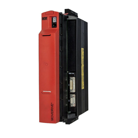
Page 4: Movidrive ® B
® MOVIDRIVE Information regarding UL ® MOVIDRIVE Information regarding UL 1.1.1 Field wiring power terminals • Use 60/75 °C copper wire only – Models with suffix 0003 to 0300. Use 75 °C copper wire only – Models with suffix 0370 to 2500. •... - Page 5 ® MOVIDRIVE Information regarding UL 1.1.3 Branch circuit protection Integral solid state short circuit protection does not provide branch circuit protection. Branch circuit protection must be provided in accordance with the National Electrical Code and any additional local codes. For maximum fuse rating see tables below. AC 400/500 V units ®...
- Page 6 ® MOVIDRIVE Information regarding UL 1.1.4 Motor Overload Protection The units are provided with motor overload protection with a trip current adjusted to 150% of the rated motor current. 1.1.5 Ambient temperature The units are suitable for an ambient temperature of 40 °C, max. 60 °C with derated out- put current.
-
Page 7: Wiring Diagram For Basic Unit
® MOVIDRIVE Wiring diagram for basic unit Wiring diagram for basic unit 1.2.1 Power section and brake (size 1-6) F11/F12/F13 Protective earth (shield) (AC-3) L1 L2 Line filter option NF... DC link L1' L2' L3' connection F14/F15 F14/F15 F14/F15 L1 L2 L3 Power section (AC-3) (AC-3) - Page 8 ® MOVIDRIVE Wiring diagram for basic unit Brake rectifier in Install the connection cables between the brake rectifier and the brake separately from the control cabinet other power cables when installing the brake rectifier in the control cabinet. Joint instal- lation is only permitted with shielded power cables.
- Page 9 ® MOVIDRIVE Wiring diagram for basic unit 1.2.3 Braking resistor BW... / BW...-...-T /BW...-...-P Power section Power section Power section +R -R +R -R +R -R Wirkt auf K11 BW...-...-P BW...-...-T affects affects BW... When the internal temperature When the signal contact F16 trips, switch trips, K11 must be opened K11 must be opened and DIØØ"/Controller When the external bimetal relay...
-
Page 10: Movidrive ® Compact
® MOVIDRIVE compact Information Regarding UL ® MOVIDRIVE compact Information Regarding UL 2.1.1 Field Wiring Power Terminals • Use 60/75 °C copper wire only – Models with suffix 0003 to 0300. Use 75 °C copper wire only – Models with suffix 0370 to 0750. •... - Page 11 ® MOVIDRIVE compact Information Regarding UL 2.1.3 Branch Circuit Protection Integral solid state short circuit protection does not provide branch circuit protection. Branch circuit protection must be provided in accordance with the National Electrical Code and any additional local codes. For maximum fuse rating see tables below.
-
Page 12: Wiring Diagram For Basic Unit
® MOVIDRIVE compact Wiring diagram for basic unit Wiring diagram for basic unit 2.2.1 Wiring the power section and brake F11/F12/F13 Protective earth (shield) (AC-3) L1 L2 NF... line filter option DC link L1' L2' L3' connection* F14/F15 F14/F15 F14/F15 L1 L2 L3 Power section (AC-3) - Page 13 ® MOVIDRIVE compact Wiring diagram for basic unit Brake rectifier in Install the connection cables between the brake rectifier and the brake separately from control cabinet other power cables when installing the brake rectifier in the control cabinet. Joint instal- lation is only permitted with shielded power cables.
-
Page 14: Movidrive ® A
® MOVIDRIVE Information Regarding UL ® MOVIDRIVE Information Regarding UL 3.1.1 Field Wiring Power Terminals • Use 60/75 °C copper wire only – Models with suffix 0003 to 0300. Use 75 °C copper wire only – Models with suffix 0370 to 0750. •... - Page 15 ® MOVIDRIVE Information Regarding UL 3.1.3 Branch Circuit Protection Integral solid state short circuit protection does not provide branch circuit protection. Branch circuit protection must be provided in accordance with the National Electrical Code and any additional local codes. For maximum fuse rating see tables below. 400/500 V units ®...
-
Page 16: Wiring Diagram For Basic Unit
® MOVIDRIVE Wiring diagram for basic unit Wiring diagram for basic unit 3.2.1 Connection of the power section and brake F11/F12/F13 Protective earth conductor (shield) (AC-3) L1 L2 Option NF... input filter DC link L1' L2' L3' connection F14/F15 F14/F15 F14/F15 L1 L2 L3 DC link... - Page 17 ® MOVIDRIVE Wiring diagram for basic unit Brake rectifier in Route the connection cables between the brake rectifier and the brake separately from switch cabinet other power cables when installing the brake rectifier in the switch cabinet. Joint routing is only permitted if the power cables are shielded. Operating Instructions –...
- Page 20 SEW-EURODRIVE—Driving the world SEW-EURODRIVE Driving the world SEW-EURODRIVE GmbH & Co KG P.O. Box 3023 D-76642 Bruchsal/Germany Phone +49 7251 75-0 Fax +49 7251 75-1970 [email protected] www.sew-eurodrive.com...