Table of Contents
Operating Instructions
Operating Instructions
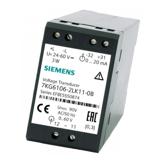
Transducer with auxiliary power
for alternating voltage or alternating current (RMS)
with expanded start range
with expanded end range
with non-linear characteristic curve
7KG6106 and 7KG6113
Compact device for DIN rail mounting
Operating Instructions
A5E38679986B / RS-AB
1
Operating
Instructions
SIMEAS-T
s
Table of Contents

Related Manuals for Siemens 7KG6106


Summary of Contents for Siemens 7KG6106
- Page 1 Operating Instructions Operating Instructions Transducer with auxiliary power for alternating voltage or alternating current (RMS) with expanded start range with expanded end range with non-linear characteristic curve 7KG6106 and 7KG6113 Compact device for DIN rail mounting Operating Instructions A5E38679986B / RS-AB...
-
Page 2: Safety Instructions
If you would like further information or if particular problems arise which are not covered in sufficient detail in the documentation, please request the necessary information from your local Siemens office or contact the addresses on the back cover of the operating instructions directly. - Page 3 SIMEAS-T - Transducer with auxiliary power QUALIFIED PERSONNEL Unqualified intervention in the device/system or failure to heed the safety warnings in this manual can lead to serious injury or material damage. Therefore, only suitably qualified personnel are permitted to service this device/system. Qualified personnel in the sense of the safety-related notices in these operating instructions or on the product itself are persons who •...
- Page 4 SIMEAS-T - Transducer with auxiliary power...
-
Page 5: Table Of Contents
10.3 Installation material ......................18 11 Commissioning ........................18 12 Maintenance .......................... 18 13 Calibrating and testing ......................19 Siemens Aktiengesellschaft © SIEMENS AG 2006, 2011, 2014, 2015. 2016 All Rights Reserved Subject to change without prior notice A5E38679986B / RS-AB... - Page 6 SIMEAS-T - Transducer with auxiliary power...
-
Page 7: Operating Instructions
SIMEAS-T - Transducer with auxiliary power Operating Instructions 1 Area of application Transducers are used to convert different measured signals from high-voltage and low-voltage systems into proportional output variables. Areas of application are, for example Power supply and distribution for areas in which measured signals must be sent over a large distance. -
Page 8: Performance Characteristics
SIMEAS-T - Transducer with auxiliary power 3 Performance characteristics • High measuring precision • Powerful output signal circuits • High system safety and reliability • CE mark • High immunity to EMC interference • Compliance with relevant national and international standards •... -
Page 9: Operating Principle
SIMEAS-T - Transducer with auxiliary power 4 Operating principle The transformer (1) transfers the input signal I or U to the effective value Direct voltage converter (2) which drives the output amplifier (4) via the expansion circuit (3). Fed by the auxiliary source (6), the output amplifier provides load- independent current I or load-independent voltage U proportional to the input... -
Page 10: Technical Specifications
SIMEAS-T - Transducer with auxiliary power 6 Technical specifications General input transducer Only for connecting to alternating voltage systems! Maximum voltage to earth 500 V ~ Power consumption of the measuring circuit approx. 0.06 VA Permissible modulation range 1.2 I or 1.2 U Rated frequency f 50 Hz, 60 Hz... - Page 11 SIMEAS-T - Transducer with auxiliary power Auxiliary power U Rated input voltage U 24-60 V; 110-220 V – Direct voltage – Alternating voltage 100; 115; 230 V ~; 50/60 Hz Input range – Direct voltage ± 20% – Alternating voltage ±...
-
Page 12: Rating Plate Symbols
SIMEAS-T - Transducer with auxiliary power Safety in accordance with DIN EN 61010 Part 1 Overvoltage category Degree of pollution Fire resistance class electrically isolated Dielectric strength (test voltage) with type test – input relative to output = 5.5 kV, 50 Hz, sine –... -
Page 13: Description
SIMEAS-T - Transducer with auxiliary power 8 Description The transducers in the enclosure are permanently wired and tested functional units. They have a snap-on mounting for a 35 mm standard mounting rail according to DIN EN 50022. Inputs and outputs can be safely connected to the screw terminals. The devices are silicone-free, halogen-free and flame-resistant. -
Page 14: Ordering Data
SIMEAS-T - Transducer with auxiliary power 9 Ordering data Ordering data for alternating voltage (G) MUU Name Order no. Code Device ↑ ↑ ↑ ↑ │ │ │ │ Input signal E │ │ │ Rated frequency f 50 Hz │... - Page 15 SIMEAS-T - Transducer with auxiliary power Continued: Ordering data for alternating voltage (G) MUU Name Order no. Code Device 7KG 6 ↑ ↑ │ │ │ │ Auxiliary power │ 24 to 60 V DC │ 110 to 220 V DC │...
- Page 16 SIMEAS-T - Transducer with auxiliary power Ordering data for alternating current (G) MUI Name Order no. Code Device 7KG 6 ↑ ↑ ↑ ↑ ↑ ↑ │ │ │ │ │ │ Input signal E │ │ │ │ │ Rated frequency f 50 Hz │...
-
Page 17: Mounting And Operation
SIMEAS-T - Transducer with auxiliary power 10 Mounting and operation WARNING! When electrical devices are operated, certain parts necessarily conduct dangerous voltages. Failure to heed the operating notices can therefore lead to serious injury or property damage. The device should only be mounted and electrically connected by appropriately qualified personnel. -
Page 18: Installation Material
SIMEAS-T - Transducer with auxiliary power Notes for the fuses to be used: For devices that are supplied with AC auxiliary energy, a 100 mA time-lag fuse according to IEC 60127-2 must be connected upstream in the control cabinet installation. Appropriate protection must be provided for the measuring circuits during the installation: •... -
Page 19: Calibrating And Testing
SIMEAS-T - Transducer with auxiliary power 13 Calibrating and testing WARNING! The work must be done in accordance with the specifications and performance instructions of accident prevention regulation VBG 4.0. in particular 8. "Permissible discrepancies while working on active parts". A suitable electrical tool must be used. The transducer has to be opened and the modules removed for calibration. - Page 20 SIMEAS-T - Transducer with auxiliary power Test circuit for voltage and current transducers (example for current output). 1 Alternating voltage encoder (THD ≤ 1%) 0 to 600 V or Alternating current encoder (THD ≤ 1%) range 0 to 10 A 2 Voltmeter, class 0.01 (for voltage input) 3 Ammeter, class 0.01, Ri ≤...
- Page 21 SIMEAS-T - Transducer with auxiliary power Arrangement of the balancing potentiometers Transducer with linear characteristic curve from 0 to A Full-scale value Feed E = E ± 0.05% E , set output end value with trim potentiometer R33 Set A = A ±...
- Page 22 SIMEAS-T - Transducer with auxiliary power Transducer with expanded start range and suppressed end range Example: Transducer with range: 0 to 0.05 to U 0 to 0.8 to A EN ≙ Basic settings R32: Stop left R33: Stop right Break point Feed U = 0.05 U ±...
- Page 23 SIMEAS-T - Transducer with auxiliary power...
- Page 24 SIMEAS-T - Transducer with auxiliary power Contact Please talk to your Siemens contact (http://www.siemens.com/automation/partner) at one of our agencies or local offices if you have any questions about the products described here and do not find the answers in this manual.