Siemens SIMATIC S7-200 System Manual
Hide thumbs
Also See for SIMATIC S7-200:
- System manual (554 pages) ,
- Getting started (65 pages) ,
- Manual (55 pages)
Table of Contents
Quick Links
SIMATIC
S7-200
Programmable Controller
System Manual
This manual has the order number:
6ES7298-8FA21-8BH0
03/2000
Edition 02
Preface, Contents
Introducing the S7-200 Micro
PLC
Getting Started with an S7-200
Programming System
Basic Concepts for Programming
an S7-200 CPU
CPU Memory: Data Types and
Addressing Modes
CPU and Input/Output
Setting Up Communications
Hardware and Network
Communications
Conventions for S7-200
Using USS Protocol Instructions
to Communicate with Drives
Appendices
Execution Times for STL
Instructions
S7-200 Quick Reference
Information
1
2
3
4
5
6
7
8
9
10
11
A
B
C
D
E
F
G
Table of Contents

Related Manuals for Siemens SIMATIC S7-200


Summary of Contents for Siemens SIMATIC S7-200
- Page 1 Preface, Contents Introducing the S7-200 Micro Installing an S7-200 Micro PLC Getting Started with an S7-200 Programming System SIMATIC Basic Concepts for Programming an S7-200 CPU S7-200 CPU Memory: Data Types and Addressing Modes Programmable Controller CPU and Input/Output Configuration Setting Up Communications Hardware and Network System Manual...
-
Page 2: Edition
Siemens. This product can only function correctly and safely if it is transported, stored, set up, and instal- led correctly, and operated and maintained as recommended. - Page 3 Preface Purpose The S7-200 series is a line of micro-programmable logic controllers (Micro PLCs) that can control a variety of automation applications. Compact design, low cost, and a powerful instruction set make the S7-200 controllers a perfect solution for controlling small applications. The wide variety of CPU sizes and voltages and the Windows-based programming tool give you the flexibility you need to solve your automation problems.
- Page 4 CPU with other microsystem components (such as the TP070 Touch Panel or a MicroMaster drive). Agency Approvals The SIMATIC S7-200 series meets the following regulations: European Community (CE) Low Voltage Directive 73/23/EEC European Community (CE) EMC Directive 89/336/EEC Underwriters Laboratories, Inc.: UL 508 Listed (Industrial Control Equipment) Canadian Standards Association: CSA C22.2 Number 142 Certified (Process...
-
Page 5: Installing An S7-200 Micro Plc
Preface How to Use This Manual If you are a first-time (novice) user of S7-200 Micro PLCs, you should read the entire S7-200 Programmable Controller System Manual . If you are an experienced user, refer to the manual table of contents or index to find specific information. The S7-200 Programmable Controller System Manual is organized according to the following topics: “Introducing the S7-200 Micro PLC”... - Page 6 For assistance in answering technical questions, for training on this product, or for ordering, contact your Siemens distributor or sales office. For Internet information about Siemens products and services, technical support, or FAQs (frequently asked questions) and application tips, use the following Internet addresses: http://www.ad.siemens.de...
-
Page 7: Table Of Contents
Contents Introducing the S7-200 Micro PLC ........Comparing the Features of the S7-200 Micro PLCs . -
Page 8: Table Of Contents
Contents CPU Memory: Data Types and Addressing Modes ......Direct Addressing of the CPU Memory Areas . -
Page 9: Table Of Contents
Contents SIMATIC Move Instructions ........9-102 9.10 SIMATIC Table Instructions... -
Page 10: Table Of Contents
Contents S7-200 Specifications ........... General Technical Specifications . -
Page 11: Introducing The S7-200 Micro Plc
Introducing the S7-200 Micro PLC The S7-200 series is a line of micro-programmable logic controllers (Micro PLCs) that can control a variety of automation applications. Figure 1-1 shows an S7-200 Micro PLC. The compact design, expandability, low cost, and powerful instruction set of the S7-200 Micro PLC make a perfect solution for controlling small applications. -
Page 12: Comparing The Features Of The S7-200 Micro Plcs
Introducing the S7-200 Micro PLC Comparing the Features of the S7-200 Micro PLCs Equipment Requirements Figure 1-2 shows the basic S7-200 Micro PLC system, which includes an S7-200 CPU, a personal computer, STEP 7-Micro/WIN 32, version 3.1 programming software, and a communications cable. In order to use a personal computer (PC), you must have one of the following: A PC/PPI cable A communications processor (CP) and multipoint interface (MPI) cable... - Page 13 Introducing the S7-200 Micro PLC Table 1-1 Summary of the S7-200 CPU Feature CPU 221 CPU 222 CPU 224 CPU 226 Physical Size of Unit 90 mm x 80 mm x 90 mm x 80 mm x 120.5 mm x 190 mm x 62 mm 62 mm...
- Page 14 Introducing the S7-200 Micro PLC Table 1-1 Summary of the S7-200 CPU Communications Number of comm ports: 1 (RS-485) 1 (RS-485) 1 (RS-485) 2 (RS-485) Protocols supported Port 0: PPI, DP/T, Freeport PPI, DP/T, Freeport PPI,DP/T, Freeport PPI,DP/T, Freeport Port 1: PPI, DP/T, Freeport PROFIBUS peer-to-peer (NETR/NETW)
-
Page 15: Major Components Of The S7-200 Micro Plc
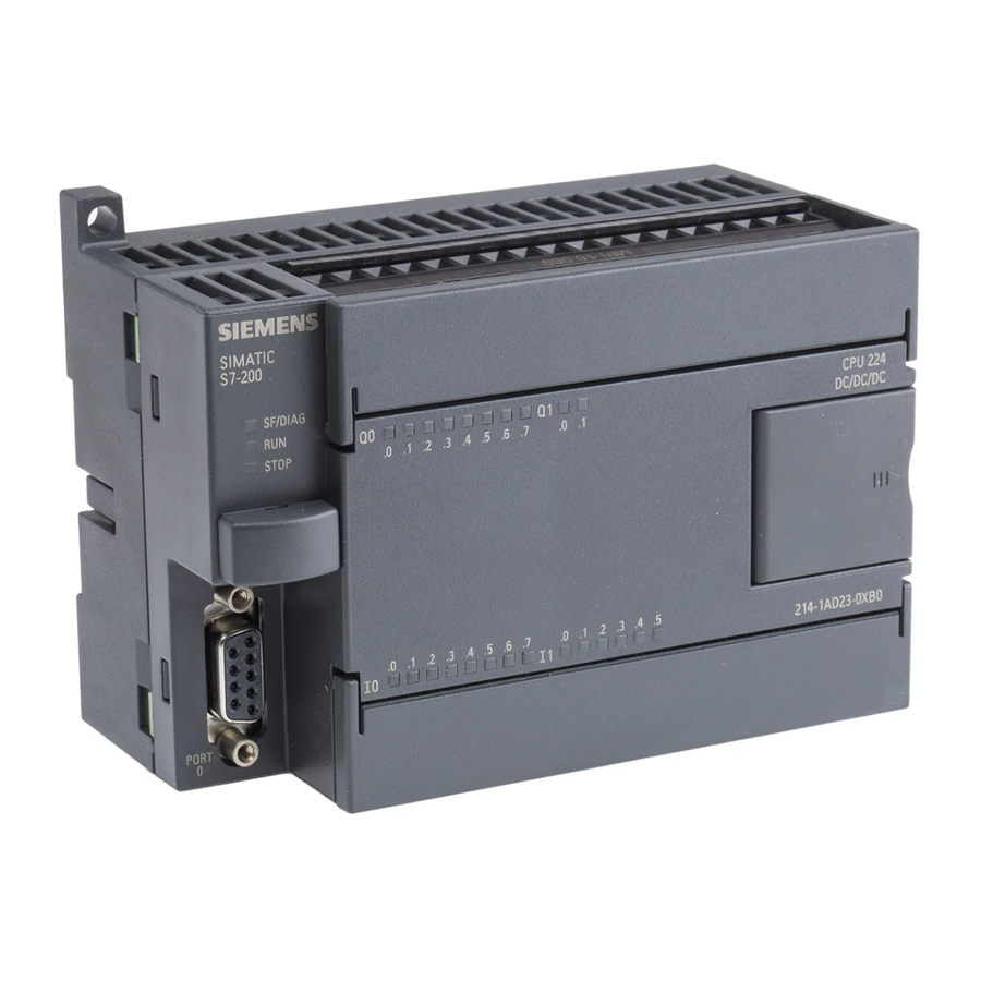
Introducing the S7-200 Micro PLC Major Components of the S7-200 Micro PLC An S7-200 Micro PLC consists of an S7-200 CPU alone or with a variety of optional expansion modules. S7-200 CPU The S7-200 CPU combines a central processing unit (CPU), power supply, and discrete I/O points into a compact, stand-alone device. - Page 16 Introducing the S7-200 Micro PLC Figure 1-3 shows the S7-200 CPU. Top terminal door Power terminal Status LEDs Output terminal Front access door Cartridge Mode switch Potentiometer Expansion I/O connection Communication Bottom terminal door Port Input terminal Sensor power Figure 1-3 S7-200 CPU Expansion Modules The S7-200 CPU provides a certain number of local I/O.
-
Page 17: Maximum I/O Configurations
Introducing the S7-200 Micro PLC Maximum I/O Configurations The maximum I/O configuration for each CPU system is subject to the following limits: Module count: CPU 221: no expansion available CPU 222: maximum of 2 expansion modules CPU 224 and CPU 226: maximum of 7 expansion modules No more than 2 of the 7 modules can be intelligent expansion modules (EM 277 PROFIBUS-DP modules) Digital Image Register size: The logical space that each CPU allows for digital... - Page 18 Introducing the S7-200 Micro PLC Table 1-2 Current Supplied by S7-200 CPU CPU 22x Expansion Module 5 VDC Current Supplied 5 VDC Current Consumption - ma for Expansion I/O - ma CPU 222 EM 221 DI8 x DC24V CPU 224 EM 222 DO8 x DC24V CPU 226 CPU 226...
- Page 19 Introducing the S7-200 Micro PLC Table 1-3 Maximum I/O Configurations for S7-200 CPUs Digital Digital Analog Analog Module 5V ma Inputs Outputs Inputs Outputs CPU 221 No expansion possible CPU 222 Max Digital In/Out +340 2 x EM 223 DI16/DO16 x DC24V -320 or -300 2 x EM 223 DI16/DO16 x DC24V/Rly...
- Page 20 Introducing the S7-200 Micro PLC S7-200 Programmable Controller System Manual 1-10 A5E00066097-02...
-
Page 21: Installing An S7-200 Plc
Installing an S7-200 PLC The installation of the S7-200 equipment is designed to be easy. You can use the mounting holes to attach the modules to a panel, or you can use the built-in clips to mount the modules onto a standard (DIN) rail. The small size of the S7-200 allows you to make efficient use of space. -
Page 22: Panel Layout Considerations
Installing an S7-200 PLC Panel Layout Considerations Installation Configuration You can install an S7-200 either on a panel or on a standard rail. You can mount the S7-200 either horizontally or vertically. You can connect the S7-200 to expansion modules by one of these methods: A flexible ribbon cable with mating connector is built into the I/O module for easy connection to the PLC or another expansion module. - Page 23 Installing an S7-200 PLC 25 mm        (1 in.)        Front of the Mounting enclosure surface Clearance for cooling        S7-200 S7-200 Â...
- Page 24 Installing an S7-200 PLC Panel-Mounting Dimensions S7-200 CPUs and expansion modules include mounting holes to facilitate installation on panels. Figure 2-4 through Figure 2-7 provide the mounting dimensions for the different S7-200 CPUs and expansion modules. 90 mm (3.54 in.) 4 mm 82 mm (0.16 in.)
- Page 25 Installing an S7-200 PLC 4 mm 196 mm (0.16 in.) ( 7.84 in.) 4 mm 188 mm (0.16 in.) (7.52 in.) 88 mm (3.46 in.) 96 mm CPU 226 (3.78 in.) 80 mm (3.15 in.) Mounting holes (M4 or No. 8) 4 mm (0.16 in.) Figure 2-6...
-
Page 26: Installing And Removing An S7-200 Micro Plc Or Expansion Module
Installing an S7-200 PLC Installing and Removing an S7-200 Micro PLC or Expansion Module Mounting an S7-200 Micro PLC or Expansion Module onto a Panel Warning Attempts to install or remove S7-200 CPUs or related equipment with power applied could cause electric shock or faulty operation of equipment. Failure to disable all power to the S7-200 and related equipment during installation or removal procedures may result in death or serious personal injury, and/or damage to equipment. - Page 27 Installing an S7-200 PLC Installing an S7-200 Micro PLC or Expansion Module onto a Standard Rail Warning Attempts to install or remove S7-200 CPUs or related equipment when they are powered up could cause electric shock or faulty operation of equipment. Failure to disable all power to the S7-200 CPUs and related equipment during installation or removal procedures may result in death or serious personal injury, and/or damage to equipment.
- Page 28 Installing an S7-200 PLC Removing the S7-200 Micro PLC or Expansion Module Warning Attempts to install or remove S7-200 CPUs or related equipment when they are powered up could cause electric shock or faulty operation of equipment. Failure to disable all power to the S7-200 CPUs and related equipment during installation or removal procedures may result in death or serious personal injury, and/or damage to equipment.
-
Page 29: Installing The Field Wiring
Installing an S7-200 PLC Installing the Field Wiring Warning Attempts to install or remove S7-200 CPUs or related equipment when they are powered up could cause electric shock or faulty operation of equipment. Failure to disable all power to the S7-200 CPUs and related equipment during installation or removal procedures may result in death or serious personal injury, and/or damage to equipment. - Page 30 Installing an S7-200 PLC Warning Control devices can fail in an unsafe condition, resulting in unexpected operation of controlled equipment. Such unexpected operations could result in death or serious personal injury, and/or equipment damage. Consider using an emergency stop function, electromechanical overrides, or other redundant safeguards that are independent of the programmable controller.
- Page 31 Installing an S7-200 PLC The following descriptions are an introduction to general isolation characteristics of the S7-200 family, but some features may be different on specific products. Consult your product specifications in Appendix A for information about which circuits include isolation boundaries and the ratings of the boundaries. Isolation boundaries rated less than 1,500 VAC are designed as functional isolation only, and should not be depended on as safety boundaries.
- Page 32 Installing an S7-200 PLC Using the Removable Terminal Block Connector The removable terminal block connector (Figure 2-10) allows field wiring connections to remain fixed when you remove and re-install the S7-200 CPU and I/O expansion modules. To remove the terminal block connector from the CPU or expansion module, follow these steps: Raise the top terminal door of the CPU or expansion module.
- Page 33 Installing an S7-200 PLC Guidelines for AC Installation The following items are general wiring guidelines for AC installations. Refer to Figure 2-11. [a] Provide a single disconnect switch that removes power from the CPU, all input circuits, and all output (load) circuits. [b] Provide overcurrent devices to protect the CPU power supply, the output points, and the input points.
- Page 34 Installing an S7-200 PLC Guidelines for DC Installation The following items are general wiring guidelines for DC installations. Refer to Figure 2-12. [a] Provide a single disconnect switch that removes power from the CPU, all input circuits, and all output (load) circuits. [b] Provide overcurrent devices to protect the CPU power supply, [c] the output points, and [d] the input points.
- Page 35 Installing an S7-200 PLC Floating [f] or Grounded [g] S7-200 EM 222 EM 221 DC/DC/DC 24 VDC Figure 2-12 DC System Installation S7-200 Programmable Controller System Manual 2-15 A5E00066097-02...
-
Page 36: Using Suppression Circuits
Installing an S7-200 PLC Using Suppression Circuits General Guidelines Equip inductive loads with suppression circuits that limit voltage rise on loss of power. Use the following guidelines to design adequate suppression. The effectiveness of a given design depends on the application, and you must verify it for a particular use. - Page 37 Installing an S7-200 PLC Protecting Relays That Control DC Power Resistor/capacitor networks, as shown in Figure 2-15, can be used for low voltage (30 V) DC relay applications. Connect the network across the load. where minimum R = 12 Ω +VDC Inductor where K is 0.5 µF/A to 1 µF/A...
-
Page 38: Power Considerations
Installing an S7-200 PLC Power Considerations The S7-200 CPUs have an internal power supply that provides power for the CPU, the expansion modules, and other 24 VDC user power requirements. Use the following information as a guide for determining how much power (or current) the CPU can provide for your configuration. - Page 39 Installing an S7-200 PLC Calculating a Sample Power Requirement Table 2-1 shows a sample calculation of the power requirements for an S7-200 Micro PLC that includes the following: CPU 224 AC/DC/Relay 3 each EM 223 8 DC In/8 Relay Out 1 each EM 221 8 DC In This installation has a total of 46 inputs and 34 outputs.
- Page 40 Installing an S7-200 PLC Calculating Your Power Requirement Use the table below to determine how much power (or current) the CPU can provide for your configuration. Refer to Appendix A for the power budgets of your CPU and the power requirements of your expansion modules. Power Budget 5 VDC 24 VDC...
-
Page 41: Getting Started With An S7-200 Programming System
Getting Started with an S7-200 Programming System This chapter describes how to set up an S7-200 programming system. The S7-200 programming system described in this chapter consists of: An S7-200 CPU A PC or programming device with STEP 7-Micro/WIN 32 installed An interconnecting cable Chapter Overview Section... -
Page 42: Overview
TP070 Touch Panel for use with STEP 7-Micro/WIN 32 Toolbox A personal computer (PC) with an 80586 or greater processor and 16 Mbytes of RAM, or a Siemens programming device with STEP 7-Micro/WIN 32 installed (such as a PG 740). The minimum computer requirement is an 80486 processor with 8 Mbytes. -
Page 43: Quick Start For Step 7-Micro/Win 32
Getting Started with an S7-200 Programming System Quick Start for STEP 7-Micro/WIN 32 Pre-Installation Instructions Before running the setup procedure, do the following: If a previous version of STEP 7-Micro/WIN 32 is installed, back up all STEP 7-Micro/WIN projects to diskette. Make sure all applications are closed, including the Microsoft Office toolbar. - Page 44 Getting Started with an S7-200 Programming System Review the README X .TXT file included on your CD or diskettes for the most recent information about STEP 7-Micro/WIN 32. (In the x position, the letter A = German, B = English, C = French, D = Spanish, E = Italian.) Note Installing STEP 7-Micro/WIN in the same directory as an existing installation uninstalls the existing installation.
-
Page 45: How Do I Set Up Communications Using The Pc/Ppi Cable?
Getting Started with an S7-200 Programming System How Do I Set Up Communications Using the PC/PPI Cable? This section explains how to set up communications between an S7-200 CPU and your personal computer using the PC/PPI cable. This is single master configuration with no other hardware (such as a modem or a programming device) installed. - Page 46 Getting Started with an S7-200 Programming System How Do I Verify the Default Parameters for My Communications Interface? You can verify the default parameters for your interface by following the steps below: In the STEP 7-Micro/WIN 32 window, click the Communications icon, or select View >...
- Page 47 Getting Started with an S7-200 Programming System Communications Links Communications Setup PC/PPI cable Double click the icon representing the PLC Address: 0 Set PG/PC Interface (V5.0) wish to communicate with. Access Path Double click the module icon to change to Access Point of the Application: communication parameters.
- Page 48 Getting Started with an S7-200 Programming System Set the PG/PC Interface (V5.0) Access Path Properties - PC/PPI cable (PPI) Local Connection Station Parameters Address: Timeout: Network Parameters Multiple Master Network 9.6 kbps Transmission Rate: Highest Station Address: Standard Cancel Help Cancel Help Figure 3-3...
-
Page 49: How Do I Complete The Communications Connection?
Getting Started with an S7-200 Programming System How Do I Complete the Communications Connection? Once you have installed STEP 7-Micro/WIN 32 software on your PC and set up your PC for communications with the PC/PPI cable, you are ready to complete the logical connection to the S7-200 CPU. -
Page 50: How Do I Change The Communications Parameters For My Plc?
Getting Started with an S7-200 Programming System How Do I Change the Communications Parameters for My PLC? Once you are communicating with the S7-200 CPU, you can verify or change the communications parameters for your CPU. To change the communications parameters, follow the steps below: Click the System Block icon on the navigation bar, or select View >... -
Page 51: Basic Concepts For Programming An S7-200 Cpu
Basic Concepts for Programming an S7-200 CPU Before you start to program your application using the S7-200 CPU, you should become familiar with some of the basic operational features of the CPU. Chapter Overview Section Description Page Guidelines for Designing a Micro PLC System Concepts of an S7-200 Program Concepts of the S7-200 Programming Languages and Editors Understanding the Differences between SIMATIC and... -
Page 52: Guidelines For Designing A Micro Plc System
Basic Concepts for Programming an S7-200 CPU Guidelines for Designing a Micro PLC System There are many methods for designing a Micro PLC system. This section provides some general guidelines that can apply to many design projects. Of course, you must follow the directives of your own company’s procedures and of the accepted practices of your own training and location. - Page 53 Basic Concepts for Programming an S7-200 CPU Creating the Functional Specifications Write the descriptions of operation for each section of the process or machine. Include the following topics: Input/output (I/O) points Functional description of the operation Permissive states (states that must be achieved before allowing action) for each actuator (solenoids, motors, drives, etc.) Description of the operator interface Interfaces with other sections of the process or machine...
- Page 54 Basic Concepts for Programming an S7-200 CPU Specifying the Operator Stations Based on the requirements of the functional specifications, create drawings of the operator stations. Include the following items: Overview showing the location of each operator station in relation to the process or machine Mechanical layout of the devices (display, switches, lights, etc.) for the operator station...
-
Page 55: Concepts Of An S7-200 Program
Basic Concepts for Programming an S7-200 CPU Concepts of an S7-200 Program Relating the Program to Inputs and Outputs The basic operation of the S7-200 CPU is very simple: The CPU reads the status of the inputs. The program that is stored in the CPU uses these inputs to evaluate the control logic. -
Page 56: Concepts Of The S7-200 Programming Languages And Editors
Basic Concepts for Programming an S7-200 CPU Concepts of the S7-200 Programming Languages and Editors The S7-200 CPUs offer many types of instructions that allow you to solve a wide variety of automation tasks. There are two basic instruction sets available in the S7-200 CPU: SIMATIC and IEC 1131-3. - Page 57 Basic Concepts for Programming an S7-200 CPU As you can see from Figure 4-3, this text-based concept is very similar to assembly language programming. The CPU executes each instruction in the order dictated by the program, from top to bottom, and then restarts at the top. STL and assembly language are also similar in another sense.
- Page 58 Basic Concepts for Programming an S7-200 CPU Ladder Logic Editor The STEP 7-Micro/WIN 32 Ladder Logic (LAD) editor allows you to build programs that resemble the equivalent of an electrical wiring diagram. Ladder programming is probably the method of choice for many PLC programmers and maintenance personnel.
- Page 59 Basic Concepts for Programming an S7-200 CPU Function Block Diagram Editor The STEP 7-Micro/WIN 32 Function Block Diagram (FBD) editor allows you to view the instructions as logic boxes that resemble common logic gate diagrams. There are no contacts and coils as found in the LAD editor, but there are equivalent instructions that appear as box instructions.
-
Page 60: Understanding The Differences Between Simatic And Iec 1131-3 Instructions
Basic Concepts for Programming an S7-200 CPU Understanding the Differences between SIMATIC and IEC 1131-3 Instructions SIMATIC Instruction Set Most PLCs offer similar basic instructions, but there are usually small differences in their appearance, operation, etc., from vendor to vendor. The SIMATIC instruction set is designed for the S7-200 CPU. - Page 61 Basic Concepts for Programming an S7-200 CPU Consider these points when you select IEC 1131-3 instructions: It is usually easier to learn how to create programs for different brands of PLCs. Fewer instructions are available (as specified by the standard) but you can always use many of the SIMATIC instructions as well.
- Page 62 Basic Concepts for Programming an S7-200 CPU Table 4-3 IEC 1131-3 Complex Data Types Complex Data Types Description Address Range On-Delay Timer 1 ms T32, T96 10 ms T33 to T36, T97 to T100 100 ms T37 to T63, T101 to T255 Off-Delay Timer 1 ms T32, T96...
- Page 63 Basic Concepts for Programming an S7-200 CPU Strong data type checking is performed only within IEC 1131-3 modes. See Table 4-4. Table 4-4 Strong Data Type Checking User Selected and Equivalent Data Types User Selected Data Type Equivalent Data Type BOOL BOOL BYTE...
- Page 64 Basic Concepts for Programming an S7-200 CPU No Data Type Checking The no data type checking mode is available only for SIMATIC global variables where the data types are not selectable. In this mode, all data types of equivalent size are automatically assigned to the symbol. For example, a symbol that is assigned the address VD100 is assigned the data types shown in Table 4-6 automatically by STEP 7-Micro/WIN 32.
- Page 65 Basic Concepts for Programming an S7-200 CPU Selecting Between SIMATIC and IEC 1131-3 Programming Modes Since IEC 1131-3 is strongly data typed, and SIMATIC is not strongly data typed, STEP 7-Micro/WIN 32 does not allow you to move programs between the two different editing modes.
- Page 66 Basic Concepts for Programming an S7-200 CPU Using Direct Addressing in IEC for Overloaded Instructions IEC 1131-3 programming modes permit you to use directly represented memory locations as a part of instruction parameter configuration. Both variables and memory locations can be used within parameters. Remember that directly represented memory locations do not contain explicit type information.
- Page 67 Basic Concepts for Programming an S7-200 CPU Using Conversion Instructions Conversion instructions permit the movement from one data type to another. STEP 7-Micro/WIN 32 supports the conversion instructions shown in Table 4-10 for moving values between the simple data types. Table 4-10 Conversion Instructions Conversion Instruction Strong Data Type Checking...
-
Page 68: Basic Elements For Constructing A Program
Basic Concepts for Programming an S7-200 CPU Basic Elements for Constructing a Program The S7-200 CPU continuously executes your program to control a task or process. You create this program with STEP 7-Micro/WIN 32 and download it to the CPU. From the main program, you can call different subroutines or interrupt routines. - Page 69 Basic Concepts for Programming an S7-200 CPU SIMATIC LAD MAIN PROGRAM OB1 Network 1 SBR0 SM0.1 SUBROUTINE 0 Network 1 SM0.0 MOV_B ATCH SMB34 EVNT INTERRUPT ROUTINE 0 Network 1 SM0.0 MOV_W AIW4 VW100 Figure 4-7 SIMATIC LAD Program for Using a Subroutine and an Interrupt Routine Statement List Main Program OB1 Network 1...
- Page 70 Basic Concepts for Programming an S7-200 CPU SIMATIC FBD MAIN PROGRAM OB1 Network 1 SBR0* SM0.1 *Refer to page 9-149 SUBROUTINE 0 Network 1 MOV_B ATCH SM0.0 SMB34 EVNT INTERRUPT ROUTINE 0 Network 1 MOV_W SM0.0 >1 AIW4 VW100 Figure 4-9 SIMATIC FBD Program for Using a Subroutine and an Interrupt Routine IEC LAD MAIN PROGRAM...
- Page 71 Basic Concepts for Programming an S7-200 CPU IEC FBD MAIN PROGRAM OB1 Network 1 SBR0 %SM0.1 SUBROUTINE 0 Network 1 MOVE ATCH %SM0.0 %SMB34 EVENT INTERRUPT ROUTINE 0 Network 1 MOVE %SM0.0 %AIW4 &VW100 Figure 4-11 IEC FBD Program for Using a Subroutine and an Interrupt Routine S7-200 Programmable Controller System Manual 4-21 A5E00066097-02...
-
Page 72: Understanding The Scan Cycle Of The Cpu
Basic Concepts for Programming an S7-200 CPU Understanding the Scan Cycle of the CPU The S7-200 CPU is designed to execute a series of tasks, including your program, repetitively. This cyclical execution of tasks is called the scan cycle. During the scan cycle shown in Figure 4-12, the CPU performs most or all of the following tasks: Reading the inputs... - Page 73 Basic Concepts for Programming an S7-200 CPU The CPU does not update analog inputs as part of the normal scan cycle unless digital filtering of analog inputs is enabled. Digital filtering is provided as a user selectable option and can be individually enabled for each analog input point. Digital filtering is intended for use with low-cost analog modules that do not provide filtering internal to the module.
- Page 74 Basic Concepts for Programming an S7-200 CPU The CPU reserves the process-image output register in increments of eight bits (one byte). If the CPU or expansion module does not provide a physical output point for each bit of the reserved byte, you cannot reallocate these bits to subsequent modules in the I/O chain.
-
Page 75: Selecting The Mode Of Operation For The Cpu
Basic Concepts for Programming an S7-200 CPU Selecting the Mode of Operation for the CPU The S7-200 CPU has two modes of operation: STOP: The CPU is not executing the program. You can download a program or configure the CPU when the CPU is in STOP mode. RUN: The CPU is running the program. - Page 76 Basic Concepts for Programming an S7-200 CPU Changing the Operating Mode with STEP 7-Micro/WIN 32 As shown in Figure 4-13, you can use STEP 7-Micro/WIN 32 to change the operating mode of the CPU. To enable the software to change the operating mode, you must set the mode switch on the CPU to either TERM or RUN.
-
Page 77: Creating A Password For The Cpu
Basic Concepts for Programming an S7-200 CPU Creating a Password for the CPU All models of the S7-200 CPU provide password protection for restricting access to specific CPU functions. A password authorizes access to the CPU functions and memory: without a password, the CPU provides unrestricted access. When password protected, the CPU prohibits all restricted operations according to the configuration provided when the password was installed. - Page 78 Basic Concepts for Programming an S7-200 CPU Configuring the CPU Password You can use STEP 7-Micro/WIN 32 to create the password for the CPU. Select the menu command View > System Block and click the Password tab. See Figure 4-14. Enter the appropriate level of access for the CPU, then enter and verify the password for the CPU.
- Page 79 Basic Concepts for Programming an S7-200 CPU What to Do If You Forget the CPU Password If you forget the CPU password, you must clear the CPU memory and reload your program. Clearing the CPU memory puts the CPU in STOP mode and resets the CPU to the factory-set defaults, except for the CPU address, baud rate, and the time-of-day clock.
-
Page 80: Debugging And Monitoring Your Program
Basic Concepts for Programming an S7-200 CPU Debugging and Monitoring Your Program STEP 7-Micro/WIN 32 provides a variety of tools for debugging and monitoring your program. Using First Scan/Multiple Scans to Monitor Your Program You can specify that the CPU execute your program for a limited number of scans (from 1 scan to 65,535 scans). - Page 81 Basic Concepts for Programming an S7-200 CPU Using a Status Chart to Monitor and Modify Your Program As shown in Figure 4-16, you can use a Status Chart to read, write, force, and monitor variables while the program is running. Use the menu command View > Status Chart.
- Page 82 Basic Concepts for Programming an S7-200 CPU Displaying the Status of the Program in Ladder Logic You can monitor the status of the ladder program by using STEP 7-Micro/WIN 32. STEP 7-Micro/WIN 32 must be displaying ladder logic. Ladder status displays the status of all instruction operand values.
- Page 83 Basic Concepts for Programming an S7-200 CPU LAD Program status (end of scan) Tools Windows Help SIMATIC LAD Name Var Type Data Type Comment BOOL Start TEMP TEMP BOOL Stop Network 1 I0.0 ADD_I +777=VW0 +800=VW4 +23=VW2 MAIN SBR_0 INT_0 Figure 4-17 Displaying the Status of a Program in Ladder Logic Displaying the Status of the Program in Function Block Diagram...
- Page 84 Basic Concepts for Programming an S7-200 CPU You can use the Options Tool to configure the status screen. Select Tools > Options and then select the FBD Status tab. Table 4-14 shows the FBD status display options. To open the FBD status window, select the status icon from the toolbar (Figure 4-18).
- Page 85 Basic Concepts for Programming an S7-200 CPU Displaying the Status of the Program in Statement List If you view your program using the STL editor, STEP 7-Micro/WIN 32 provides a method of monitoring the execution status of the program on an instruction-by-instruction basis.
- Page 86 Basic Concepts for Programming an S7-200 CPU To choose the categories of values that you want to appear in the STL status window, select Tools > Options and then select the STL Status tab. You can choose to monitor three categories of values in the STL status window: Operands (up to three operands per instruction) Logic Stack (up to four of the most recent values from the logic stack) Instruction Status Bits (up to twelve instruction status bits)
- Page 87 Basic Concepts for Programming an S7-200 CPU Forcing Specific Values The S7-200 CPU allows you to force any or all of the I/O points (I and Q bits). In addition, you can also force up to 16 internal memory values (V or M) or analog I/O values (AI or AQ).
- Page 88 Basic Concepts for Programming an S7-200 CPU Unforces all CPU Reads the forced values forced values. from the CPU. Unforces the current selection. Forces the current selection. Help Status Chart Address Format Current Value New Value Indicates that this variable Start_1 is forced.
-
Page 89: Editing In Run Mode
Basic Concepts for Programming an S7-200 CPU 4.10 Editing in RUN Mode CPU 224 Rel. 1.10 (and higher) and CPU 226 Rel. 1.00 (and higher) models support RUN mode edits. The RUN mode edit capability is intended to allow you to make small changes to a user program with minimal disturbance to the process being controlled by the program. - Page 90 Basic Concepts for Programming an S7-200 CPU The warning in Figure 4-23 appears. When you select the “Continue” button, the program from the connected CPU is uploaded and the application is in RUN mode edit. No restrictions on edits are enforced. Program Edit in RUN Mode Changing the program during RUN mode can result in unex- Warning!
- Page 91 Basic Concepts for Programming an S7-200 CPU Before You Download in RUN Mode RUN mode editing allows you to download your program edits while the CPU is in RUN mode. To decide whether to download your program to the CPU in RUN mode or in STOP mode, consider the following facts: If the control logic for an output is deleted in a RUN mode edit, the output maintains its last state until the next power cycle or transition to STOP mode.
-
Page 92: Background Time
Basic Concepts for Programming an S7-200 CPU 4.11 Background Time You can configure the percentage of the scan cycle that will be dedicated to processing communications requests that are associated with a RUN mode edit compilation or STL status gathering. As you increase the percentage of time that is dedicated to processing communication requests, you increase scan time, which makes your control process run more slowly. -
Page 93: Error Handling For The S7-200 Cpu
Basic Concepts for Programming an S7-200 CPU 4.12 Error Handling for the S7-200 CPU The S7-200 CPU classifies errors as either fatal errors or non-fatal errors. You can use STEP 7-Micro/WIN 32 to view the error codes that were generated by an error. Select PLC >... - Page 94 Basic Concepts for Programming an S7-200 CPU Responding to Fatal Errors Fatal errors cause the CPU to stop the execution of your program. Depending upon the severity of the fatal error, it can render the CPU incapable of performing any or all functions. The objective for handling fatal errors is to bring the CPU to a safe state from which the CPU can respond to interrogations about the existing error conditions.
- Page 95 Basic Concepts for Programming an S7-200 CPU Responding to Non-Fatal Errors Non-fatal errors can degrade some aspect of the CPU performance, but they do not render the CPU incapable of executing your program or updating the I/O. As shown in Figure 4-25, you can use STEP 7-Micro/WIN 32 to view the error codes that were generated by the non-fatal error.
- Page 96 Basic Concepts for Programming an S7-200 CPU S7-200 Programmable Controller System Manual 4-46 A5E00066097-02...
-
Page 97: Cpu Memory: Data Types And Addressing Modes
CPU Memory: Data Types and Addressing Modes The S7-200 CPU provides specialized areas of memory to make the processing of the control data faster and more efficient. Chapter Overview Section Description Page Direct Addressing of the CPU Memory Areas SIMATIC Indirect Addressing of the CPU Memory Areas 5-13 Memory Retention for the S7-200 CPU 5-15... -
Page 98: Direct Addressing Of The Cpu Memory Areas
CPU Memory: Data Types and Addressing Modes Direct Addressing of the CPU Memory Areas The S7-200 CPU stores information in different memory locations that have unique addresses. You can explicitly identify the memory address that you want to access. This allows your program to have direct access to the information. Using the Memory Address to Access Data To access a bit in a memory area, you specify the address, which includes the memory area identifier, the byte address, and the bit number. - Page 99 CPU Memory: Data Types and Addressing Modes You can access data in many CPU memory areas (V, I, Q, M, S, L, and SM) as bytes, words, or double words by using the byte-address format. To access a byte, word, or double word of data in the CPU memory, you must specify the address in a way similar to specifying the address for a bit.
- Page 100 CPU Memory: Data Types and Addressing Modes Representation of Numbers Table 5-1 shows the range of integer values that can be represented by the different sizes of data. Real (or floating-point) numbers are represented as 32-bit, single-precision numbers whose format is: +1.175495E-38 to +3.402823E+38 (positive), and -1.175495E-38 to -3.402823E+38 (negative).
- Page 101 CPU Memory: Data Types and Addressing Modes Addressing the Variable (V) Memory Area You can use V memory to store intermediate results of operations being performed by the control logic in your program. You can also use V memory to store other data pertaining to your process or task.
- Page 102 CPU Memory: Data Types and Addressing Modes Addressing the Local (L) Memory Area The S7-200 PLCs provide 64 bytes of local (L) memory of which 60 can be used as scratchpad memory or for passing formal parameters to subroutines. If you are programming in either LAD or FBD, STEP 7-Micro/WIN 32 reserves the last four bytes of local memory for its own use.
- Page 103 CPU Memory: Data Types and Addressing Modes Addressing the Timer (T) Memory Area In the S7-200 CPU, timers are devices that count increments of time. The S7-200 timers have resolutions (time-base increments) of 1 ms, 10 ms, or 100 ms. There are two variables that are associated with a timer: Current value: this 16-bit signed integer stores the amount of time counted by the timer.
- Page 104 CPU Memory: Data Types and Addressing Modes Addressing the Counter (C) Memory Area In the S7-200 CPU, counters are devices that count each low-to-high transition event on the counter input(s). The CPU provides three types of counters: one type counts up only, one type counts down, and one type counts both up and down. There are two variables that are associated with a counter: Current value: this 16-bit signed integer stores the accumulated count.
- Page 105 CPU Memory: Data Types and Addressing Modes Addressing the Analog Inputs (AI) The S7-200 converts a real-world, analog value (such as temperature or voltage) into a word-length (16-bit) digital value. You access these values by the area identifier (AI), size of the data (W), and the starting byte address. Since analog inputs are words and always start on even-number bytes (such as 0, 2, or 4), you access them with even-number byte addresses (such as AIW0, AIW2, or AIW4), as shown in Figure 5-5.
- Page 106 CPU Memory: Data Types and Addressing Modes Addressing the Accumulators (AC) Accumulators are read/write devices that can be used like memory. For example, you can use accumulators to pass parameters to and from subroutines and to store intermediate values used in a calculation. The CPU provides four 32-bit accumulators (AC0, AC1, AC2, and AC3).
- Page 107 CPU Memory: Data Types and Addressing Modes Addressing the High-Speed Counters (HC) High-speed counters are designed to count very high-speed events independent of the CPU scan. High-speed counters have a signed, 32-bit integer counting value (or current value). To access the count value for the high-speed counter, you specify the address of the high-speed counter, using the memory type (HC) and the counter number (such as HC0).
- Page 108 CPU Memory: Data Types and Addressing Modes Using Constant Values You can use a constant value in many of the S7-200 instructions. Constants can be bytes, words, or double words. The CPU stores all constants as binary numbers, which can then be represented in decimal, hexadecimal, ASCII or floating point formats.
-
Page 109: Simatic Indirect Addressing Of The Cpu Memory Areas
CPU Memory: Data Types and Addressing Modes SIMATIC Indirect Addressing of the CPU Memory Areas Indirect addressing uses a pointer to access the data in memory. The S7-200 CPU allows you to use pointers to address the following memory areas indirectly: I, Q, V, M, S, T (current value only), and C (current value only). - Page 110 CPU Memory: Data Types and Addressing Modes Modifying Pointers You can change the value of a pointer. Since pointers are 32-bit values, use double-word instructions to modify pointer values. Simple mathematical operations, such as adding or incrementing, can be used to modify pointer values. Remember to adjust for the size of the data that you are accessing: When accessing bytes, increment the pointer value by one.
-
Page 111: Memory Retention For The S7-200 Cpu
CPU Memory: Data Types and Addressing Modes Memory Retention for the S7-200 CPU The S7-200 CPU provides several methods to ensure that your program, the program data, and the configuration data for your CPU are properly retained. See Figure 5-11. The CPU provides an EEPROM to store permanently all of your program, user-selected data areas, and the configuration data for your CPU. - Page 112 CPU Memory: Data Types and Addressing Modes User program CPU configuration Data block (DB1): up to the maximum V memory range S7-200 CPU User program User program CPU configuration CPU configuration User program V memory V memory CPU configuration DB1 (permanent area) M memory M memory...
- Page 113 CPU Memory: Data Types and Addressing Modes Automatically Saving the Data from the Bit Memory (M) Area When the CPU Loses Power If the first 14 bytes of M memory (MB0 to MB13) are configured to be retentive, they are permanently saved to the EEPROM when the CPU loses power. As shown in Figure 5-14, the CPU moves these retentive areas of M memory to the EEPROM.
- Page 114 CPU Memory: Data Types and Addressing Modes At power on, the CPU checks the RAM to verify that the super capacitor successfully maintained the data stored in RAM memory. If the RAM was successfully maintained, the retentive areas of RAM are left unchanged. As shown in Figure 5-16, the non-retentive areas of V memory are restored from the corresponding permanent area of V memory in the EEPROM.
- Page 115 CPU Memory: Data Types and Addressing Modes Defining Retentive Ranges of Memory You can define up to six retentive ranges to select the areas of memory you want to retain through power cycles (see Figure 5-18). You can define ranges of addresses in the following memory areas to be retentive: V, M, C, and T.
-
Page 116: Using Your Program To Store Data Permanently
CPU Memory: Data Types and Addressing Modes Using Your Program to Store Data Permanently You can save a value (byte, word, or double word) stored in V memory to EEPROM. This feature can be used to store a value in any location of the permanent V memory area. - Page 117 CPU Memory: Data Types and Addressing Modes Limiting the Number of Programmed Saves to EEPROM Since the number of save operations to the EEPROM is limited (100,000 minimum, and 1,000,000 typical), you should ensure that only necessary values are saved. Otherwise, the EEPROM can be worn out and the CPU can fail.
-
Page 118: Using A Memory Cartridge To Store Your Program
CPU Memory: Data Types and Addressing Modes Using a Memory Cartridge to Store Your Program The CPUs support an optional memory cartridge that provides a portable EEPROM storage for your program. The CPU stores the following elements on the memory cartridge: User program Data stored in the permanent V memory area of the EEPROM CPU configuration (system block) - Page 119 CPU Memory: Data Types and Addressing Modes You can install or remove the memory cartridge while the CPU is powered on. To install the memory cartridge, remove the plastic cover from the PLC, and insert the memory cartridge on the PLC. (The memory cartridge is keyed for proper installation.) After the memory cartridge is installed, use the following procedure to copy the program.
- Page 120 CPU Memory: Data Types and Addressing Modes Restoring the Program and Memory with a Memory Cartridge To transfer the program from a memory cartridge to the CPU, you must cycle the power to the CPU with the memory cartridge installed. As shown in Figure 5-21, the CPU performs the following tasks after a power cycle (when a memory cartridge is installed): The RAM is cleared.
-
Page 121: Cpu And Input/Output Configuration
CPU and Input/Output Configuration The inputs and outputs are the system control points: the inputs monitor the signals from the field devices (such as sensors and switches), and the outputs control pumps, motors, or other devices in your process. You can have local I/O (provided by the CPU) or expansion I/O (provided by an expansion I/O module). -
Page 122: Local I/O And Expansion I/O
CPU and Input/Output Configuration Local I/O and Expansion I/O The inputs and outputs are the system control points: the inputs monitor the signals from the field devices (such as sensors and switches), and the outputs control pumps, motors, or other devices in your process. You can have local I/O (provided by the CPU) or expansion I/O (provided by an expansion I/O module): The S7-200 CPU provides a certain number of digital local I/O points. - Page 123 CPU and Input/Output Configuration Examples of Local and Expansion I/O Figure 6-1 and Figure 6-2 provide examples that show how different hardware configurations affect the I/O numbering. Notice that some of the configurations contain gaps in the addressing that cannot be used by your program. CPU 221 Process-image I/O register assigned to physical I/O: I0.0...
-
Page 124: Using The Selectable Input Filter To Provide Noise Rejection
CPU and Input/Output Configuration Using the Selectable Input Filter to Provide Noise Rejection The S7-200 CPUs allow you to select input filter that defines a delay time (selectable from 0.2 ms to 12.8 ms) for some or all of the local digital input points. (See Appendix A for information about your particular CPU.) As shown in Figure 6-3, each delay specification applies to groups of four input points. -
Page 125: Pulse Catch
CPU and Input/Output Configuration Pulse Catch The S7-200 CPUs provide a pulse catch feature for some or all of the local digital input points. See Appendix A for more information about your particular CPU. The pulse catch feature allows you to capture high-going pulses or low-going pulses that are of such a short duration that they would not always be seen when the CPU reads the digital inputs at the beginning of the scan cycle. - Page 126 CPU and Input/Output Configuration A block diagram of the digital input circuit is shown in Figure 6-5. External digital input Pulse catch Optical Digital input Input to CPU function isolation filter Pulse catch enable Figure 6-5 Digital Input Circuit The response of an enabled pulse catch function to various input conditions is shown in Figure 6-6.
- Page 127 CPU and Input/Output Configuration To access the pulse catch configuration screen, select the menu command View > System Block from the main menu bar and click on the Pulse Catch Bits tab. Figure 6-7 shows the Pulse Catch configuration screen. To enable the pulse catch function on a particular input, click the corresponding checkbox.
-
Page 128: Using The Output Table To Configure The States Of The Outputs
CPU and Input/Output Configuration Using the Output Table to Configure the States of the Outputs The S7-200 CPU provides the capability either to set the state of the digital output points to known values upon a transition to the STOP mode, or to leave the outputs in the state they were in before the transition to the STOP mode. -
Page 129: Analog Input Filter
CPU and Input/Output Configuration Analog Input Filter With the CPU 222, CPU 224, and CPU 226 you can select software filtering on individual analog inputs. The filtered value is the average value of the sum of a preselected number of samples of the analog input. The filter specification (number of samples and deadband) is the same for all analog inputs for which filtering is enabled. -
Page 130: High-Speed I/O
CPU and Input/Output Configuration High-Speed I/O Your S7-200 CPU provides high-speed I/O for controlling high-speed events. For more information about the high-speed I/O provided by each CPU, refer to the specifications in Appendix A. High-Speed Counters The S7-200 CPUs provide integrated high-speed counter functions that count external events at rates up to 20 kHz without degrading the performance of the CPU. - Page 131 CPU and Input/Output Configuration From this table you can see that if you are using HSC0 in modes 3 through 10 (Clock and Direction or any of the two-phase clocking modes), you cannot use HSC3 because HSC0 and HSC3 both use I0.1. The same is true for HSC4 and HSC5, which both use I0.4.
- Page 132 CPU and Input/Output Configuration High-Speed Pulse Output The S7-200 CPUs support high-speed pulse outputs. Q0.0 and Q0.1 can either generate high-speed pulse train outputs (PTO) or perform pulse width modulation (PWM) control. The pulse train function provides a square wave (50% duty cycle) output for a specified number of pulses and a specified cycle time.
-
Page 133: Analog Adjustments
CPU and Input/Output Configuration Analog Adjustments The analog adjustment potentiometers are located under the front access cover of the module. You can adjust these potentiometers to increase or decrease values that are stored in bytes of Special Memory (SMB28 and SMB29). These read-only values can be used by the program for a variety of functions, such as updating the current value for a timer or a counter, entering or changing the preset values, or setting limits. - Page 134 CPU and Input/Output Configuration S7-200 Programmable Controller System Manual 6-14 A5E00066097-02...
-
Page 135: Setting Up Communications Hardware And Network
Setting Up Communications Hardware and Network Communications This chapter describes communications using STEP 7-Micro/WIN 32, version 3.0. Previous versions of the software may operate differently. It also tells you how to set up your communications hardware and how to set up an S7-200 communications network. -
Page 136: What Are My Communication Choices?
Setting Up Communications Hardware and Network Communications What Are My Communication Choices? You can arrange the S7-200 CPUs in a variety of configurations to support network communications. You can install the STEP 7-Micro/WIN 32 software on a personal computer (PC) that has a Windows 95, Windows 98, or Windows NT operating system, or you can install it on a SIMATIC programming device (such as a PG 740). - Page 137 Setting Up Communications Hardware and Network Communications Master devices TD 200 OP15 CPU 224 CP card MPI cable (RS-485) CPU 221 CPU 224 CPU 221 CPU 224 Slave devices Figure 7-2 Example of a CP Card with Master and Slave Devices How Do I Choose My Communication Configuration? Table 7-1 shows the possible hardware configurations and baud rates that STEP 7-Micro/WIN 32 supports.
- Page 138 12 Mbaud Data Communications Using the CP or MPI Card Siemens offers several network interface cards that you can put into a personal computer or SIMATIC programming device. These cards allow the PC or SIMATIC programming device to act as a network master. These cards contain dedicated hardware to assist the PC or programming device in managing a multiple-master network, and can support different protocols at several baud rates.
- Page 139 Setting Up Communications Hardware and Network Communications How Do I Set Up Communications within STEP 7-Micro/WIN 32? Within STEP 7-Micro/WIN 32, there is a Setup Communications dialog box that you can use to configure your communications setup. You can use one of the following ways to find this dialog box: Select the menu command View >...
- Page 140 Setting Up Communications Hardware and Network Communications In the Communications Setup dialog box, double-click the top icon on the right-hand side. The Set the PG/PC Interface dialog box appears. See Figure 7-4. Communications Links Communications Setup PC/PPI cable Address: 0 Double click the icon representing the PLC wish to communicate with.
-
Page 141: Installing And Removing Communication Interfaces
Setting Up Communications Hardware and Network Communications Installing and Removing Communication Interfaces You can install or remove communications hardware by using the Install/Remove Interfaces dialog box shown in Figure 7-5. On the left side of this dialog box is a list of hardware types that you have not installed yet. - Page 142 Setting Up Communications Hardware and Network Communications Special Hardware Installation Information for Windows NT Users Installing hardware modules under the Windows NT operating system is slightly different from installing hardware modules under Windows 95. Although the hardware modules are the same for either operating system, installation under Windows NT requires more knowledge of the hardware that you want to install.
-
Page 143: Selecting And Changing Parameters
Setting Up Communications Hardware and Network Communications Selecting and Changing Parameters Selecting the Correct Interface Parameter Set and Setting It Up When you have reached the Set the PG/PC Interface dialog box, be sure that “Micro/WIN” appears in the Access Point of Application list box (see Figure 7-4). The Set the PG/PC Interface box is common to several different applications, such as STEP 7 and WinCC, so you may need to tell the program the application for which you are setting parameters. - Page 144 Setting Up Communications Hardware and Network Communications Setting Up the PC/PPI Cable (PPI) Parameters This section explains how to set up the PPI parameters for the Windows 95, Windows 98, or Windows NT 4.0 operating systems, and for the PC/PPI cable. From the Set the PG/PC Interface dialog box, if you are using the PC/PPI cable and you click the “Properties...”...
- Page 145 Setting Up Communications Hardware and Network Communications Follow these steps to set up the PPI parameters: In the PPI tab, in the Station Parameters area, select a number in the Address box. This number indicates where you want STEP 7-Micro/WIN 32 to reside on the programmable controller network.
- Page 146 Setting Up Communications Hardware and Network Communications Click the Local Connection tab. See Figure 7-8. In the Local Connection tab, select the COM port to which your PC/PPI cable is connected. If you are using a modem, select the COM port to which the modem is connected and select the Use Modem check box.
-
Page 147: Instructions
Setting Up Communications Hardware and Network Communications Note If you are using the PPI parameter set, STEP 7-Micro/WIN 32 does not support two different applications running on the same MPI or CP card at the same time. Close the other application before connecting STEP 7-Micro/WIN 32 to the network through the MPI or CP card. - Page 148 Setting Up Communications Hardware and Network Communications Setting Up the CP or MPI Card (PPI) Parameters This section explains how to set up the PPI parameters for the Windows 95, Windows 98 or Windows NT 4.0 operating systems and the following hardware: CP 5511 CP 5611 From the Set the PG/PC Interface dialog box, if you are using any of the MPI or...
- Page 149 Setting Up Communications Hardware and Network Communications Properties - MPI-ISA Card (PPI) Station Parameters Address: Timeout: Network Parameters Multiple Master Network 9.6 kbps Transmission Rate: Highest Station Address: Standard Cancel Help Figure 7-10 MPI-ISA Card (PPI) Properties Sheet S7-200 Programmable Controller System Manual 7-15 A5E00066097-02...
-
Page 150: Communicating With Modems
Setting Up Communications Hardware and Network Communications Communicating With Modems Setting Up the Communications Parameters When Using Modems To set up communications parameters between your programming device or PC and the CPU when using modems, you must use the module parameter set for the PC/PPI cable. - Page 151 Setting Up Communications Hardware and Network Communications Communications Links Communications Setup PC/PPI cable Double click the icon representing the PLC Address: 0 you wish to communicate with. Bausch Induline IL 4K4 Double click the interface icon to change to (11-bit, 9600 Baud, Predefined) communication parameters.
- Page 152 Setting Up Communications Hardware and Network Communications In the Communications Setup dialog box, double-click on the first modem icon. The Modem Setup dialog box for the local modem appears (Figure 7-12). In the Local Modem area, select your modem type. If your modem is not listed, select the “Add”...
- Page 153 Setting Up Communications Hardware and Network Communications 11. The Configure dialog box appears (Figure 7-13). If you are using a predefined modem, the only field that you can edit in this dialog box is the Timeout area. The timeout is the length of time that the local modem attempts to set up a connection to the remote modem.
- Page 154 Setting Up Communications Hardware and Network Communications Setting Up The Remote Modem: In the Communications Setup dialog box, double-click on the second modem icon (Figure 7-11). The Modem Setup dialog box for the remote modem appears (Figure 7-14). In the Remote Modem area, select your modem type. If your modem is not listed, select the “Add”...
- Page 155 Setting Up Communications Hardware and Network Communications Configure Bausch Induline IL 14K4 (11-bit) Initialization String AT&F08K0X3&D0\N0 Communication String *W=9600,8,N,1 Suffix &Y0&W0^M Program/Test Status Cancel Advanced... Figure 7-15 Remote Modem Configuration S7-200 Programmable Controller System Manual 7-21 A5E00066097-02...
- Page 156 Setting Up Communications Hardware and Network Communications Disconnect your remote modem from your local machine (your programming device or PC). Connect the remote modem to your S7-200 programmable controller. Connect your local modem to your programming device or PC. Connecting the Modems: To connect your modem, double-click on the Connect Modem icon in the Communications Setup dialog box.
- Page 157 Setting Up Communications Hardware and Network Communications Using a 10-Bit Modem to Connect an S7-200 CPU to a STEP 7-Micro/WIN 32 Master Using STEP 7-Micro/WIN 32 on a PC with a Windows 95, Windows 98, or Windows NT operating system, or using a SIMATIC programming device (such as a PG 740) as a single-master device, you can connect to only one S7-200 CPU.
- Page 158 Setting Up Communications Hardware and Network Communications This configuration allows only one master device and one slave device. In this configuration, the S7-200 controller requires one start bit, eight data bits, no parity bit, one stop bit, asynchronous communication, and a transmission speed of 9600/19,200 baud.
- Page 159 CPU If there are multiple CPUs connected to the remote modem, you will need a Siemens programming port connector on a PROFIBUS network (see Figure 7-24 for the bias and termination of interconnecting cables).
- Page 160 Setting Up Communications Hardware and Network Communications This configuration allows only one master device and supports only the PPI protocol. In order to communicate through the PPI interface, the S7-200 PLC requires that the modem use an 11-bit data string. In this mode, the S7-200 controller requires one start bit, eight data bits, one parity bit (even parity), one stop bit, asynchronous communication, and a transmission speed of 9600/19,200 baud.
-
Page 161: Network Overview
Setting Up Communications Hardware and Network Communications Network Overview Network Masters Figure 7-21 shows a configuration with a personal computer connected to several S7-200 CPUs. STEP 7-Micro/WIN 32 is designed to communicate with one S7-200 CPU at a time; however, you can access any CPU on the network. The CPUs in Figure 7-21 could be either slave or master devices. - Page 162 Setting Up Communications Hardware and Network Communications Figure 7-22 shows a more general network including multiple master devices. Higher baud rates and more connections are made possible by using the EM 277 PROFIBUS-DP module. S7-300 with SIMATIC CPU 315-2 DP ET 200B programming device CPU 224...
- Page 163 Setting Up Communications Hardware and Network Communications Network Communication Protocols The S7-200 CPUs support a variety of communication capabilities. Depending on the S7-200 CPU that you use, your network can support one or more of the following communication protocols: Point-to-Point Interface (PPI) Multipoint Interface (MPI) PROFIBUS These protocols are based upon the Open System Interconnection (OSI)
- Page 164 Setting Up Communications Hardware and Network Communications PPI Protocol PPI is a master/slave protocol. In this protocol the master devices (other CPUs, SIMATIC programming devices, or TD 200s) send requests to the slave devices and the slave devices respond. Slave devices do not initiate messages, but wait until a master sends them a request or polls them for a response.
- Page 165 Setting Up Communications Hardware and Network Communications PROFIBUS Protocol The PROFIBUS protocol is designed for high-speed communications with distributed I/O devices (remote I/O). There are many PROFIBUS devices available from a variety of manufacturers. These devices range from simple input or output modules to motor controllers and programmable controllers.
-
Page 166: Network Components
Setting Up Communications Hardware and Network Communications Network Components The communication port on each S7-200 enables you to connect it to a network bus. The information below describes this port, the connectors for the network bus, the network cable, and repeaters used to extend the network. Communication Port The communication ports on the S7-200 CPUs are RS-485 compatible on a nine-pin subminiature D connector in accordance with the PROFIBUS standard as... - Page 167 Setting Up Communications Hardware and Network Communications Network Connectors Siemens offers two types of networking connectors that you can use to connect multiple devices to a network easily. Both connectors have two sets of terminal screws to allow you to attach the incoming and outgoing network cables. Both connectors also have switches to bias and terminate the network selectively.
- Page 168 Bias and Termination of Interconnecting Cable Cable for a PROFIBUS Network Table 7-6 lists the general specifications for a PROFIBUS network cable. See Appendix E for the Siemens order number for PROFIBUS cable meeting these requirements. Table 7-6 General Specifications for a PROFIBUS Network Cable...
- Page 169 100 m (328 ft.) Network Repeaters Siemens provides network repeaters to connect PROFIBUS network segments. See Figure 7-25. The use of repeaters extends the overall network length, allows you to add devices to a network, and/or provides a way to isolate different network segments.
-
Page 170: Using The Pc/Ppi Cable With Other Devices And Freeport
Setting Up Communications Hardware and Network Communications Using the PC/PPI Cable with Other Devices and Freeport You can use the PC/PPI cable and the Freeport communication functions to connect the S7-200 CPUs to many devices that are compatible with the RS-232 standard. - Page 171 Setting Up Communications Hardware and Network Communications If you are using the PC/PPI cable in a system where Freeport communication is used, the turnaround time must be comprehended by the user program in the S7-200 CPU for the following situations: The S7-200 CPU responds to messages transmitted by the RS-232 device.
- Page 172 Setting Up Communications Hardware and Network Communications Using a Modem with a 5-Switch PC/PPI Cable You can use the 5-switch PC/PPI cable to connect the RS-232 communication port of a modem to an S7-200 CPU. Modems normally use the RS-232 control signals (such as RTS, CTS, and DTR) to allow a PC to control the modem.
- Page 173 Setting Up Communications Hardware and Network Communications To set the mode to Data Communications Equipment (DCE), you should set switch 5 to the 0 or down position (see Figure 7-27). To set the mode to Data Terminal Equipment (DTE), you should set switch 5 to the 1 or up position. Table 7-10 shows the pin numbers and functions for the RS-485 to RS-232 port of the PC/PPI cable in DTE mode.
- Page 174 Setting Up Communications Hardware and Network Communications Switch 4 of the PC/PPI cable tells the S7-200 CPU to use either a 10-bit protocol or the normal 11-bit PPI protocol. Switch 4 is used only when the CPU is communicating with STEP 7-Micro/WIN. If you are not using STEP 7-Micro/Win with a modem, switch 4 should be left in the 11-bit setting for proper operation with other devices.
- Page 175 Setting Up Communications Hardware and Network Communications Using a Modem with a 4-Switch PC/PPI Cable You can use a 4-switch PC/PPI cable to connect the RS-232 communication port of a modem to an S7-200 CPU. Modems normally use the RS-232 control signals (such as RTS, CTS, and DTR) to allow a PC to control the modem.
-
Page 176: Network Performance
Setting Up Communications Hardware and Network Communications Network Performance Optimizing Network Performance The two factors which have the greatest effect on network performance are the baud rate and the number of masters. Operating the network at the highest baud rate supported by all devices has the greatest effect on the network. Minimizing the number of masters on a network also increases the performance of the network. - Page 177 Setting Up Communications Hardware and Network Communications As a general rule, you should set the highest station address on all masters to the same value. This address should be greater than or equal to the highest master address. The S7-200 CPUs default to a value of 31 for the highest station address. Token Rotation In a token-passing network, the station that holds the token is the only station that has the right to initiate communication.
- Page 178 Setting Up Communications Hardware and Network Communications In this configuration, the TD 200 (station 3) communicates with the CPU 222 (station 2), TD 200 (station 5) communicates with CPU 222 (station 4), and so on. Also, CPU 224 (station 6) is sending messages to stations 2, 4, and 8, and CPU 224 (station 8) is sending messages to stations 2, 4, and 6.
- Page 179 Setting Up Communications Hardware and Network Communications Token hold time (T ) = (128 overhead + n data char) 11 bits/char 1/baud rate hold of master m Token rotation time (T ) = T of master 1 + T of master 2 + . . . + T hold hold hold...
- Page 180 Setting Up Communications Hardware and Network Communications Table 7-13 Token Rotation Time versus Number of Stations and Amount of Data at 19.2 kbaud Number of Stations, with Time in Seconds Bytes Transferred Bytes Transferred per Station at 19.2 kbaud stations stations stations stations...
-
Page 181: Conventions For S7-200 Instructions
Conventions for S7-200 Instructions The following conventions are used in this chapter to illustrate the equivalent ladder logic, function block diagram, and statement list instructions and the CPUs in which the instructions are available. Chapter Overview Section Description Page Concepts and Conventions for STEP 7-Micro/WIN 32 Programming Valid Ranges for the S7-200 CPUs S7-200 Programmable Controller System Manual... -
Page 182: Simatic Instructions
Conventions for S7-200 Instructions Concepts and Conventions For STEP 7-Micro/WIN 32 Programming The following diagram shows the STEP 7-Micro/WIN 32 instruction format as used throughout this chapter. A description of the components of the instruction format follows the diagram. Add Integer and Subtract Integer The Add Integer and Subtract Integer instructions add or subtract two 16-bit integers and produce a 16-bit result ADD_I... - Page 183 Conventions for S7-200 Instructions In LAD, which is patterned after Relay Ladder Logic Electrical Drawings, there is a left power rail that is energized. In LAD, contacts that are closed allow energy to flow through them to the next element and contacts that are open block that energy flow.
- Page 184 Conventions for S7-200 Instructions Table 8-1 EN/ENO Operands and Data Types for LAD and FBD Language Inputs/Outputs Operands Data Types Editor Power Flow BOOL Power Flow BOOL I, Q, M, S, SM, T, C, V, L, Power Flow BOOL I, Q, M, S, SM, T, C, V, L, Power Flow BOOL General Conventions of Programming Network: In LAD the program is divided into segments called networks.
- Page 185 Conventions for S7-200 Instructions Instruction that is dependent on power flow Instruction that is independent of power flow NEXT Instruction that is dependent on power flow NEXT Instruction that is independent of power flow Figure 8-1 LAD Diagram of Conditional and Unconditional Inputs Instructions without Outputs: Boxes that cannot cascade are drawn with no Boolean outputs.
- Page 186 Conventions for S7-200 Instructions The logical NOT condition of the state of the operand or power flow driving the input is shown by the small circle on the input to an FBD instruction. In Figure 8-2, Q0.0 is equal to the NOT of I0.0 AND I0.1. Function Block Conventions: In the FBD editor, you can use the F4, F6, and F9 keys on your keyboard to access AND, OR and box instructions.
-
Page 187: Valid Ranges For The S7-200 Cpus
Conventions for S7-200 Instructions Valid Ranges for the S7-200 CPUs Table 8-2 Summary of S7-200 CPU Memory Ranges and Features Description CPU 221 CPU 222 CPU 224 CPU 226 User program size 2 Kwords 2 Kwords 4 Kwords 4 Kwords User data size 1 Kwords 1 Kwords... - Page 188 Conventions for S7-200 Instructions Table 8-3 S7-200 CPU Operand Ranges Access Method CPU 221 CPU 222 CPU 224, CPU 226 Bit access (byte.bit) 0.0 to 2047.7 0.0 to 2047.7 0.0 to 5119.7 0.0 to 15.7 0.0 to 15.7 0.0 to 15.7 0.0 to 15.7 0.0 to 15.7 0.0 to 15.7...
- Page 189 SIMATIC Instructions This chapter describes the SIMATIC instruction set for the S7-200. Chapter Overview Section Description Page SIMATIC Bit Logic Instructions SIMATIC Compare Instructions 9-10 SIMATIC Timer Instructions 9-15 SIMATIC Counter Instructions 9-23 SIMATIC Clock Instructions 9-71 SIMATIC Integer Math Instructions 9-73 SIMATIC Real Math Instructions 9-82...
-
Page 190: Simatic Bit Logic Instructions
SIMATIC Instructions SIMATIC Bit Logic Instructions Standard Contacts These instructions obtain the referenced value from the memory or process-image register if the data type is I or Q. You can use a maximum of seven inputs to both the AND and the OR boxes. The Normally Open contact is closed (on) when the bit is equal to 1. - Page 191 SIMATIC Instructions Immediate Contacts The immediate instruction obtains the physical input value when the instruction is executed, but the process-image register is not updated. The Normally Open Immediate contact is closed (on) when the physical input point (bit) is 1. The Normally Closed Immediate contact is closed (on) when the physical input point (bit) is 0.
- Page 192 SIMATIC Instructions The NOT contact changes the state of power flow input. When power flow reaches the Not contact, it stops. When power flow does not reach the Not contact, it supplies power flow. In LAD, the NOT instruction is shown as a contact. In FBD, the NOT instruction uses the graphical negation symbol with Boolean box inputs.
- Page 193 SIMATIC Instructions Contact Examples NETWORK 1 Network 1 I0.0 I0.0 I0.1 Q0.0 I0.1 Q0.0 Network 2 NETWORK 2 I0.0 Q0.1 I0.0 Q0.1 Network 3 NETWORK 3 I0.1 Q0.2 I0.1 Q0.2 Network 1 I0.0 Q0.0 I0.1 Network 2 Q0.1 I0.0 Network 3 I0.1 Q0.2 Timing Diagram...
- Page 194 SIMATIC Instructions Output When the Output instruction is executed, the output bit in the process image register is turned on. In LAD and FBD, when the output instruction is executed, the specified bit is set to equal to power flow. In STL, the output instruction copies the top of the stack to the specified bit.
- Page 195 SIMATIC Instructions Set, Reset (N Bits) When the Set and Reset instructions are executed, the specified number of points (N) starting at the value specified by the bit or OUT parameter are set (turned on) or reset (turned off). The range of points that can be set or reset is 1 to 255. When using the Reset instruction, if the bit is specified to be either a T- or C-bit, then either the timer or counter bit is reset and the timer/counter current value is cleared.
- Page 196 SIMATIC Instructions Set Immediate, Reset Immediate (N Bits) When the Set Immediate and Reset Immediate instructions are executed, the specified number of physical output points (N) starting at the bit or OUT are immediately set (turned on) or immediately reset (turned off).
- Page 197 SIMATIC Instructions Output, Set, and Reset Examples NETWORK 1 Network 1 I0.0 I0.0 Q0.0 Q0.0 Q0.1, 1 Q0.2, 2 Q0.1 Q0.2 Network 1 Q0.0 I0.0 SM0.0 Q0.1 Q0.2 Timing Diagram I0.0 Q0.0 Q0.1 Q0.2 Q0.3 Figure 9-2 Examples of Output, Set, and Reset Instructions for SIMATIC LAD, STL, and S7-200 Programmable Controller System Manual A5E00066097-02...
-
Page 198: Simatic Compare Instructions
SIMATIC Instructions SIMATIC Compare Instructions Compare Byte The Compare Byte instruction is used to compare two values: IN1 to IN2. Comparisons include: IN1 = IN2, IN1 >= IN2, IN1 <= IN2, IN1 > IN2, IN1 < IN2, or IN1 <> IN2. Byte comparisons are unsigned. - Page 199 SIMATIC Instructions Compare Integer The Compare Integer instruction is used to compare two values: IN1 to IN2. Comparisons include: IN1 = IN2, IN1 >= IN2, IN1 <= IN2, IN1 > IN2, IN1 < IN2, or IN1 <> IN2. Integer comparisons are signed (16#7FFF > 16#8000). In LAD, the contact is on when the comparison is true.
- Page 200 SIMATIC Instructions Compare Double Word The Compare Double Word instruction is used to compare two values: IN1 to IN2. Comparisons include: IN1 = IN2, IN1 >= IN2, IN1 <= IN2, IN1 > IN2, IN1 < IN2, or IN1 <> IN2. Double word comparisons are signed (16#7FFFFFFF >...
- Page 201 SIMATIC Instructions Compare Real Compare Real instruction is used to compare two values: IN1 to IN2. Comparisons include: IN1 = IN2, IN1 >= IN2, IN1 <= IN2, IN1 > IN2, IN1 < IN2, or IN1 <> IN2. Real comparisons are signed. In LAD, the contact is on when the comparison is true.
- Page 202 SIMATIC Instructions Comparison Contact Examples Network 4 NETWORK 4 Q0.3 LDW>= VW4, VW8 >=I Q0.3 Network 4 >=I Q0.3 Timing Diagram VW4 >= VW8 VW4 < VW8 Q0.3 Figure 9-3 Examples of Comparison Contact Instructions for SIMATIC LAD. STL, and S7-200 Programmable Controller System Manual 9-14 A5E00066097-02...
-
Page 203: Simatic Timer Instructions
SIMATIC Instructions SIMATIC Timer Instructions On-Delay Timer, Retentive On-Delay Timer, Off-Delay Timer The On-Delay Timer and Retentive On-Delay Timer instructions count time when the enabling input is ON. Txxx When the current value (Txxx) is greater than or equal to the preset time (PT), the timer bit is ON. - Page 204 SIMATIC Instructions TON, TONR, and TOF timers are available in three resolutions. The resolution is determined by the timer number as shown in Table 9-1. Each count of the current value is a multiple of the time base. For example, a count of 50 on a 10-ms timer represents 500 ms.
- Page 205 SIMATIC Instructions Understanding the S7-200 Timer Instructions You can use timers to implement time-based counting functions. The S7-200 instruction set provides three types of timers as shown below. Table 9-2 shows the actions of the different timers. On-Delay Timer (TON) for timing a single interval Retentive On-Delay Timer (TONR) for accumulating a number of timed intervals Off-Delay Timer (TOF) for extending time past a false condition, such as cooling a motor after it is turned off...
- Page 206 SIMATIC Instructions The actions of the timers at different resolutions are explained below. 1-Millisecond Resolution The 1-ms timers count the number of 1-ms timer intervals that have elapsed since the active 1-ms timer was enabled. The execution of the timer instruction starts the timing;...
- Page 207 SIMATIC Instructions Updating the Timer Current Value The effect of the various ways in which current time values are updated depends upon how the timers are used. For example, consider the timer operation shown in Figure 9-4. In the case where the 1-ms timer is used (1), Q0.0 is turned on for one scan whenever the timer’s current value is updated after the normally closed contact T32 is executed and before the normally open contact T32 is executed.
- Page 208 SIMATIC Instructions On-Delay Timer Example I2.0 I2.0 I2.0 T33, 3 Timing Diagram I2.0 Maximum value = 32767 PT = 3 PT = 3 T33 (current) T33 (bit) Figure 9-5 Example of On-Delay Timer Instruction for SIMATIC LAD, FBD, and STL S7-200 Programmable Controller System Manual 9-20 A5E00066097-02...
- Page 209 SIMATIC Instructions Retentive On-Delay Timer Example I2.1 TONR TONR I2.1 I2.1 TONR T2, 10 Timing Diagram I2.1 Maximum value = 32767 PT = 10 T2 (current) T2 (bit) Figure 9-6 Example of Retentive On-Delay Timer Instruction for SIMATIC LAD, FBD, and STL S7-200 Programmable Controller System Manual 9-21 A5E00066097-02...
- Page 210 SIMATIC Instructions Off-Delay Timer Example I0.0 I0.0 I0.0 T33, 3 Timing Diagram I0.0 PT = 3 PT = 3 T33 (current) T33 (bit) Figure 9-7 Example of Off-Delay Timer Instruction for SIMATIC LAD, FBD, and STL S7-200 Programmable Controller System Manual 9-22 A5E00066097-02...
-
Page 211: Simatic Counter Instructions
SIMATIC Instructions SIMATIC Counter Instructions Count Up, Count Up/Down, Count Down The Count Up instruction counts up to the maximum Cxxx value on the rising edges of the Count Up (CU) input. When the current value (Cxxx) is greater than or equal to the Preset Value (PV), the counter bit (Cxxx) turns on. - Page 212 SIMATIC Instructions Understanding the S7-200 Counter Instructions The Up Counter (CTU) counts up from the current value of that counter each time the count-up input makes the transition from off to on. The counter is reset when the reset input turns on, or when the Reset instruction is executed. The counter stops upon reaching the maximum value (32,767).
- Page 213 SIMATIC Instructions Counter Examples I3.0 I3.0 I1.0 I1.0 I3.0 //Count Down Input I1.0 //Load Input C50, 3 Timing Diagram I3.0 Down I1.0 Load (current) (bit) Figure 9-8 Example of CTD Counter Instruction for SIMATIC LAD, FBD, and STL S7-200 Programmable Controller System Manual 9-25 A5E00066097-02...
- Page 214 SIMATIC Instructions I4.0 CTUD CTUD I4.0 I3.0 I3.0 I2.0 I2.0 I4.0 //Count Up Input I3.0 //Count Down Input I2.0 //Reset Input CTUD C48, 4 Timing Diagram I4.0 I3.0 Down I2.0 Reset (current) (bit) Figure 9-9 Example of CTUD Counter Instruction for SIMATIC LAD, FBD, and STL S7-200 Programmable Controller System Manual 9-26 A5E00066097-02...
- Page 215 SIMATIC Instructions High-Speed Counter Definition, High-Speed Counter The High-Speed Counter Definition instruction assigns a MODE to the referenced high-speed counter (HSC). HDEF See Table 9-5 on page 9-33. The High-Speed Counter instruction, when executed, configures and controls the operational mode of the MODE high-speed counter, based on the state of the HSC special memory bits.
- Page 216 SIMATIC Instructions Using the High-Speed Counter Typically, a high-speed counter is used as the drive for a drum timer, where a shaft rotating at a constant speed is fitted with an incremental shaft encoder. The shaft encoder provides a specified number of counts per revolution and a reset pulse that occurs once per revolution.
- Page 217 SIMATIC Instructions Reset interrupt Reset interrupt generated generated Counter Counter Counter Counter Disabled Enabled Disabled Enabled Start (Active High) Reset (Active High) +2,147,483,647 Counter Current Current Current Value value value frozen frozen -2,147,483,648 Counter value is somewhere in this range. Figure 9-11 Operation Example with Reset and Start Current value loaded to 0, preset loaded to 4, counting direction set to Up.
- Page 218 SIMATIC Instructions Current value loaded to 0, preset loaded to 4, counting direction set to Up. Counter enable bit set to enabled. PV=CV interrupt generated PV=CV interrupt generated and Direction Changed interrupt generated Clock External Direction Control (1 = Up) Counter Current Value...
- Page 219 SIMATIC Instructions Current value loaded to 0, preset loaded to 3, initial counting direction set to Up. Counter enable bit set to enabled. PV=CV interrupt generated and PV=CV interrupt Direction Changed interrupt generated generated Phase A Clock Phase B Clock Counter Current Value...
- Page 220 SIMATIC Instructions Connecting the Input Wiring for the High-Speed Counters Table 9-3 shows the inputs used for the clock, direction control, reset, and start functions associated with the high-speed counters. These input functions and the HSC modes of operation are described in Table 9-5 through Table 9-10. Table 9-3 Dedicated Inputs for High-Speed Counters High-Speed Counter...
- Page 221 SIMATIC Instructions Table 9-4 Input Point Assignments for High-Speed Counters and Edge Interrupts Input Point (I) Element HSC0 HSC1 HSC2 HSC3 HSC4 HSC5 Edge Interrupts Table 9-5 HSC0 Modes of Operation (CPU 221, CPU 222, CPU 224, and CPU 226) HSC0 Mode Description...
- Page 222 SIMATIC Instructions Table 9-6 HSC1 Modes of Operation (CPU 224 and CPU 226) HSC1 Mode Description I0.6 I0.7 I1.0 I1.1 Single phase up/down counter with internal direction control Clock Clock SM47.3 = 0, count down Reset SM47.3 = 1, count up SM47.3 = 1, count u Start Single phase up/down counter with external direction control...
- Page 223 SIMATIC Instructions Table 9-8 HSC3 Modes of Operation (CPU 221, CPU 222, CPU 224, and CPU 226) HSC3 Mode Description I0.1 Single phase up/down counter with internal direction control Clock SM137.3 = 0, count down SM137.3 = 1, count up Table 9-9 HSC4 Modes of Operation (CPU 221, CPU 222, CPU 224, and CPU 226) HSC4...
- Page 224 SIMATIC Instructions Addressing the High-Speed Counters (HC) To access the count value for the high-speed counter, you specify the address of the high-speed counter, using the memory type (HC) and the counter number (such as HC0). The current value of the high-speed counter is a read-only value and can be addressed only as a double word (32 bits), as shown in Figure 9-17.
- Page 225 SIMATIC Instructions Selecting the Active State and 1x/4x Mode Four counters have three control bits that are used to configure the active state of the reset and start inputs and to select 1x or 4x counting modes (quadrature counters only). These bits are located in the control byte for the respective counter and are only used when the HDEF instruction is executed.
- Page 226 SIMATIC Instructions Control Byte Once you have defined the counter and the counter mode, you can program the dynamic parameters of the counter. Each high-speed counter has a control byte that allows the counter to be enabled or disabled; the direction to be controlled (modes 0, 1, and 2 only), or the initial counting direction for all other modes;...
- Page 227 SIMATIC Instructions Status Byte A status byte is provided for each high-speed counter that provides status memory bits that indicate the current counting direction, and whether the current value is greater or equal to the preset value. Table 9-14 defines these status bits for each high-speed counter.
- Page 228 SIMATIC Instructions Note When you are using the external reset interrupt, do not attempt to load a new current value or disable, then re-enable the high-speed counter from within the interrupt routine attached to that event. A fatal error condition can result. To help you understand the operation of high-speed counters, the following descriptions of the initialization and operation sequences are provided.
- Page 229 SIMATIC Instructions Initialization Modes 0, 1, or 2 The following steps describe how to initialize HSC1 for Single Phase Up/Down Counter with Internal Direction (Modes 0, 1, or 2). Use the first scan memory bit to call a subroutine in which the initialization operation is performed.
- Page 230 SIMATIC Instructions Initialization Modes 3, 4, or 5 The following steps describe how to initialize HSC1 for Single Phase Up/Down Counter with External Direction (Modes 3, 4, or 5): Use the first scan memory bit to call a subroutine in which the initialization operation is performed.
- Page 231 SIMATIC Instructions Initialization Modes 6, 7, or 8 The following steps describe how to initialize HSC1 for Two Phase Up/Down Counter with Up/Down Clocks (Modes 6, 7, or 8): Use the first scan memory bit to call a subroutine in which the initialization operations are performed.
- Page 232 SIMATIC Instructions Initialization Modes 9, 10, or 11 The following steps describe how to initialize HSC1 for A/B Phase Quadrature Counter (Modes 9, 10, or 11): Use the first scan memory bit to call a subroutine in which the initialization operations are performed.
- Page 233 SIMATIC Instructions Change Direction in Modes 0, 1, or 2 The following steps describe how to configure HSC1 for Change Direction for Single Phase Counter with Internal Direction (Modes 0, 1, or 2): Load SMB47 to write the desired direction: SMB47 = 16#90 Enables the counter Sets the direction of the HSC to count down SMB47 = 16#98 Enables the counter...
- Page 234 SIMATIC Instructions Load a New Preset Value (Any Mode) The following steps describe how to change the preset value of HSC1 (any mode): Load SMB47 to write the desired preset value: SMB47 = 16#A0 Enables the counter Writes the new preset value Load SMD52 (double word size value) with the desired preset value.
- Page 235 SIMATIC Instructions High-Speed Counter Example MAIN OB1 Network 1 SM0.1 On the first scan, call Network 1 SBR0 subroutine 0. SM0.1 CALL End of main program. SUBROUTINE 0 Enable the counter. Network 1 Network 1 Write a new current value. SM0.0 MOV_B SM0.0...
- Page 236 SIMATIC Instructions MAIN OB1 Network 1 On the first scan, call SBR0* subroutine 0. SM0.1 End of main program. *Refer to page 9-149 SUBROUTINE 0 Network 1 HDEF MOV_B MOV_DW SM0.0 SMB47 16#F8 SMD48 MODE MOV_DW ATCH SMD52 EVENT INTERRUPT 0 Network 1 MOV_DW MOV_B...
- Page 237 SIMATIC Instructions Pulse Output The Pulse Output instruction examines the special memory bits for the pulse output (Q0.0 or Q0.1). The pulse operation defined by the special memory bits is then invoked. Operands: Constant (0 or 1) Data Types: WORD Pulse Output Ranges Q0.0 through Q0.1 222 224 Understanding the S7-200 High-Speed Output Instructions...
- Page 238 SIMATIC Instructions You can change the characteristics of a PTO or PWM waveform by modifying the desired locations in the SM area (including the control byte), and then executing the PLS instruction. You can disable the generation of a PTO or PWM waveform at any time by writing zero to the PTO/PWM enable bit of the control byte (SM67.7 or SM77.7), and then executing the PLS instruction.
- Page 239 SIMATIC Instructions The PWM Update Method bit (SM67.4 or SM77.4) in the control byte is used to specify the update type. Execute the PLS instruction to invoke the changes. Be aware that if the time base is changed, an asynchronous update will occur regardless of the state of the PWM Update Method bit.
- Page 240 SIMATIC Instructions Single Segment Pipelining In single segment pipelining, you are responsible for updating the SM locations for the next pulse train. Once the initial PTO segment has been started, you must modify immediately the SM locations as required for the second waveform, and execute the PLS instruction again.
- Page 241 SIMATIC Instructions The format of the profile table is shown in Table 9-15. An additional feature available with multiple segment PTO operation is the ability to increase or decrease the cycle time automatically by a specified amount for each pulse. Programming a positive value in the cycle time delta field increases cycle time.
- Page 242 SIMATIC Instructions Calculating Profile Table Values The multiple segment pipelining capability of the PTO/PWM generators can be useful in many applications, particularly in stepper motor control. The example shown in Figure 9-20 illustrates how to determine the profile table values required to generate an output waveform that accelerates a stepper motor, operates the motor at a constant speed, and then decelerates the motor.
- Page 243 SIMATIC Instructions Assuming that the profile table is located in V memory starting at V500, the table values used to generate the desired waveform are shown in Table 9-16. Table 9-16 Profile Table Values V Memory Address Value VB500 3 (total number of segments) VW501 500 (initial cycle time - segment #1) VW503...
- Page 244 SIMATIC Instructions The duration of a given profile segment can be useful in the process of determining correct profile table values. The length of time to complete a given profile segment can be calculated using the following formula: duration of segment = Q * ( ICT + ( ( DEL/2 ) * ( Q-1 ) ) ) where, Q = quantity of pulses in this segment ICT = initial cycle time for this segment...
- Page 245 SIMATIC Instructions Table 9-17 PTO /PWM Control Registers Q0.0 Q0.1 Status Bits SM66.4 SM76.4 PTO profile aborted due to delta calculation error 0 = no error; 1 = aborted SM66.5 SM76.5 PTO profile aborted due to user command 0 = no abort; 1 = aborted SM66.6 SM76.6...
- Page 246 SIMATIC Instructions Table 9-18 PTO/PWM Control Byte Reference Result of executing the PLS instruction Control Control Register Select PWM Update Pulse Pulse Cycle (Hex Enable Segment Time Base Mode Method Count Width Time Value) Operation 1 µs/cycle 16#81 Single Load 1 µs/cycle 16#84 Single...
- Page 247 SIMATIC Instructions PWM Initialization To initialize the PWM for Q0.0, follow these steps: Use the first scan memory bit (SM0.1) to initialize the output to 0, and call the subroutine that you need in order to perform the initialization operations. When you use the subroutine call, subsequent scans do not make the call to the subroutine.
- Page 248 SIMATIC Instructions PTO Initialization - Single Segment Operation To initialize the PTO, follow these steps: Use the first scan memory bit (SM0.1) to initialize the output to 0, and call the subroutine that you need to perform the initialization operations. This reduces scan time execution and provides a more structured program.
- Page 249 SIMATIC Instructions Changing the PTO Pulse Count - Single Segment Operation To change the PTO Pulse Count in an interrupt routine or a subroutine when using single segment PTO operation, follow these steps: Load SMB67 with a value of 16#84 for PTO using microsecond increments (or 16#8C for PTO using millisecond increments).
- Page 250 SIMATIC Instructions PTO Initialization - Multiple Segment Operation To initialize the PTO, follow these steps: Use the first scan memory bit (SM0.1) to initialize the output to 0, and call the subroutine that you need to perform the initialization operations. This reduces the scan time execution and provides a more structured program.
- Page 251 SIMATIC Instructions Example of Pulse Width Modulation Figure 9-21 shows an example of the Pulse Width Modulation. MAIN OB1 Network 1 Network 1 SM0.1 SM0.1 Q0.1 On the first scan, set Q0.1, 1 image register bit low, and CALL call subroutine 0. SBR0 Network 2 Network 2...
- Page 252 SIMATIC Instructions MAIN OB1 Network 1 Q0.1 SM0.1 SM0.0 SBR1 Network 2 SBR1 M0.0 SM0.0 SUBROUTINE 0 Network 1 MOV_B MOV_W SM0.0 16#DB SMB77 +10000 SMW80 MOV_W MOV_B +1000 SMW80 Q0.x 16#DA SMB77 SUBROUTINE 1 Network 61 MOV_W SM0.0 +5000 SMW80 Q0.X Timing Diagram...
- Page 253 SIMATIC Instructions Example of Pulse Train Output Using Single Segment Operation MAIN OB1 MAIN OB1 Network 1 Q0.0 SM0.1 Network 1 On the first scan, SM0.1 reset image Q0.0, 1 register bit low, and SBR0 CALL call subroutine 0. SUBROUTINE 0 Network 1 Network 1 Set up control byte:...
- Page 254 SIMATIC Instructions INTERRUPT 3 Network 1 SMW68 Network 1 If current cycle time MOV_W is 500 ms, then set LDW= SMW68, 500 cycle time of 1000 ms MOVW 1000, SMW68 SMW68 1000 and output 4 pulses. CRETI RETI Network 2 SMW68 Network 2 MOV_W...
- Page 255 SIMATIC Instructions MAIN OB1 Network 1 Q0.0 SM0.1 Network 2 SBR1 SM0.1 SUBROUTINE 0 Network 1 MOV_B MOV_W MOV_DW SM0.0 16#8D SMB67 +500 SMW68 SMD72 ATCH EVNT MOV_B Q0.X 16#89 SMB67 INTERRUPT 3 Network 1 MOV_W RETI SMW68 +500 +1000 SMW68 Q0.x Network 2...
- Page 256 SIMATIC Instructions Example of Pulse Train Output Using Multiple Segment Operation MAIN OB1 MAIN OB1 Network 1 Q0.0 SM0.1 Network 1 On the first scan, SM0.1 reset image Q0.0, 1 register bit low, and SBR0 CALL call subroutine 0. SUBROUTINE 0 Network 1 Network 1 Set up control byte:...
- Page 257 SIMATIC Instructions Network 1 MOVW 100, VW509 MOV_W MOVW 0, VW511 Set the initial cycle time for EN ENO segment #2 to 100 µs. MOVD 3400, VD513 MOVW 100, VW517 VW509 MOVW 1, VW519 MOVD 400, VD521 MOV_W ATCH 2, 19 EN ENO Set the delta cycle time for segment #2 to 0 µs.
- Page 258 SIMATIC Instructions MAIN OB1 Network 1 Q0.0 SM0.1 Network 2 SBR1 SM0.1 SUBROUTINE 0 Network 1 MOV_B MOV_W MOV_B SM0.0 16#A0 SMB67 +500 SMW168 VB500 MOV_B MOV_DW MOV_W +500 VW501 VW503 +200 VD505 Network 2 MOV_W MOV_W MOV_DW SM0.0 SMW511 VD513 +100 SMW509...
-
Page 259: Simatic Clock Instructions
SIMATIC Instructions SIMATIC Clock Instructions Read Real-Time Clock, Set Real-Time Clock The Read Real-Time Clock instruction reads the current time and date from the clock and loads it in an 8-byte READ_RTC buffer starting at address T. The Set Real-Time Clock instruction writes the current time and date to the clock beginning at the 8-byte buffer SET_RTC address specified by T. - Page 260 SIMATIC Instructions The time-of-day clock initializes the following date and time after extended power outages or memory has been lost: Date: 01-Jan-90 Time: 00:00:00 Day of Week Sunday The time-of-day clock in the S7-200 uses only the least significant two digits for the year, so for the year 2000, the year is represented as 00.
-
Page 261: Simatic Integer Math Instructions
SIMATIC Instructions SIMATIC Integer Math Instructions Add Integer and Subtract Integer The Add Integer and Subtract Integer instructions add or subtract two 16-bit integers and produce a 16-bit result ADD_I (OUT). In LAD and FBD: IN1 + IN2 = OUT IN1 - IN2 = OUT In STL: IN1 + OUT = OUT... - Page 262 SIMATIC Instructions Add Double Integer and Subtract Double Integer The Add Double Integer and Subtract Double Integer instructions add or subtract two 32-bit integers, and ADD_DI produce a 32-bit result (OUT). In LAD and FBD: IN1 + IN2 = OUT IN1 - IN2 = OUT In STL: IN1 + OUT = OUT...
- Page 263 SIMATIC Instructions Multiply Integer and Divide Integer The Multiply Integer instruction multiplies two 16-bit integers and produces a 16-bit product. MUL_I The Divide Integer instruction divides two 16-bit integers and produces a 16-bit quotient. No remainder is kept. The overflow bit is set if the result is greater than a word output.
- Page 264 SIMATIC Instructions Multiply Double Integer and Divide Double Integer The Multiply Double Integer instruction multiplies two 32-bit integers and produces a 32-bit product. MUL_DI The Divide Double Integer instruction divides two 32-bit integers and produces a 32-bit quotient. No remainder is kept.
- Page 265 SIMATIC Instructions Multiply Integer To Double Integer and Divide Integer To Double Integer The Multiply Integer to Double Integer instruction multiplies two 16-bit integers and produces a 32-bit product. The Divide Integer to Double Integer instruction divides two 16-bit integers and produces a 32-bit result consisting of a 16-bit remainder (most-significant) and a 16-bit quotient (least-significant).
- Page 266 SIMATIC Instructions Math Examples Network 1 NETWORK 1 I0.0 I0.0 ADD_I AC1, AC0 AC1, VD100 VW10, VD200 VD100 VW102 VW202 VD200 VW10 Network 1 ADD_I I0.0 VD100 VW202 VD200 VW10 VW102 Application Multiply Divide 4000 4000 VD200 4000 plus multiplied by divided by 6000 VD100...
- Page 267 SIMATIC Instructions Increment Byte and Decrement Byte The Increment Byte and Decrement Byte instructions add or subtract 1 to or from the input byte (IN) and place INC_B the result into the variable specified by OUT. Increment and decrement byte operations are unsigned. In LAD and FBD: IN + 1 = OUT DEC_B IN - 1 = OUT...
- Page 268 SIMATIC Instructions Increment Double Word and Decrement Double Word The Increment Double Word and Decrement Double Word instructions add or subtract 1 to or from the input INC_DW double word (IN) and place the result in OUT. In LAD and FBD: IN + 1 = OUT IN - 1 = OUT Increment and decrement double word operations are DEC_DW...
- Page 269 SIMATIC Instructions Increment, Decrement Example I4.0 INC_W I4.0 INCW DECD VD100 DEC_DW VD100 VD100 INC_W DEC_DW I4.0 VD100 VD100 Application Increment Word Decrement Double Word VD100 128000 increment decrement VD100 127999 Figure 9-26 Example of Increment/Decrement Instructions for SIMATIC LAD, STL, and FBD S7-200 Programmable Controller System Manual 9-81...
-
Page 270: Simatic Real Math Instructions
SIMATIC Instructions SIMATIC Real Math Instructions Add Real, Subtract Real The Add Real and Subtract Real instructions add or subtract two 32-bit real numbers and produce a 32-bit ADD_R real number result (OUT). In LAD and FBD: IN1 + IN2 = OUT IN1 - IN2 = OUT In STL: IN1 + OUT = OUT... - Page 271 SIMATIC Instructions Multiply Real, Divide Real The Multiply Real instruction multiplies two 32-bit real numbers, and produces a 32-bit real number result MUL_R (OUT). The Divide Real instruction divides two 32-bit real numbers, and produces a 32-bit real number quotient. In LAD and FBD: IN1 IN2 = OUT DIV_R...
- Page 272 SIMATIC Instructions Math Examples Network 1 NETWORK 1 I0.0 I0.0 ADD_R AC1, AC0 AC1, VD100 VD10, VD200 MUL_R VD100 VD100 DIV_R VD100 VD200 VD10 Network 1 MUL_R DIV_R ADD_R I0.0 VD100 VD100 VD200 VD100 VD10 Application Multiply Divide AC1 400.00 VD200 4000.0 4000.0...
-
Page 273: Simatic Numerical Functions Instructions
SIMATIC Instructions SIMATIC Numerical Functions Instructions Square Root The Square Root instruction takes the square root of a SQRT 32-bit real number (IN) and produces a 32-bit real number result (OUT) as shown in the equation: IN = OUT Error conditions that set ENO = 0: SM1.1 (overflow), SM4.3 (run-time), 0006 (indirect address) SQRT IN, OUT... - Page 274 SIMATIC Instructions Natural Exponential The Natural Exponential instruction performs the exponential operation of e raised to the power of the value in IN and places the result in OUT. The Natural Exponential can be used in combination with the Natural Logarithm to raise any real number to the power of another real number, including fractional exponents.
- Page 275 SIMATIC Instructions Inputs/Outputs Operands Data Types VD, ID, QD, MD, SMD, SD, LD, AC, Constant, *VD, *AC, *LD REAL VD, ID, QD, MD, SMD, SD, LD, AC, *VD, *AC, *LD REAL PID Loop The PID Loop instruction executes a PID loop calculation on the referenced LOOP based on the input and configuration information in Table (TBL).
- Page 276 SIMATIC Instructions The PID loop instruction (Proportional, Integral, Derivative Loop) is provided to perform the PID calculation. The top of the logic stack (TOS) must be ON (power flow) to enable the PID calculation. The instruction has two operands: a TABLE address which is the starting address of the loop table and a LOOP number which is a constant from 0 to 7.
- Page 277 SIMATIC Instructions PID Algorithm In steady state operation, a PID controller regulates the value of the output so as to drive the error (e) to zero. A measure of the error is given by the difference between the setpoint (SP) (the desired operating point) and the process variable (PV) (the actual operating point).
- Page 278 SIMATIC Instructions Since the digital computer must calculate the output value each time the error is sampled beginning with the first sample, it is only necessary to store the previous value of the error and the previous value of the integral term. As a result of the repetitive nature of the digital computer solution, a simplification in the equation that must be solved at any sample time can be made.
- Page 279 SIMATIC Instructions Integral Term The integral term MI is proportional to the sum of the error over time. The equation for the integral term as solved by the CPU is: * (SP - PV ) + MX where: is the value of the integral term of the loop output at sample time n is the loop gain is the loop sample time is the integration period of the loop (also called the integral time or reset)
- Page 280 SIMATIC Instructions Differential Term The differential term MD is proportional to the change in the error. The equation for the differential term is shown below: * ((SP - PV ) - (SP - PV n - 1 n - 1 To avoid step changes or bumps in the output due to derivative action on setpoint changes, this equation is modified to assume that the setpoint is a constant (SP ).
- Page 281 SIMATIC Instructions Converting and Normalizing the Loop Inputs A loop has two input variables, the setpoint and the process variable. The setpoint is generally a fixed value such as the speed setting on the cruise control in your automobile. The process variable is a value that is related to loop output and therefore measures the effect that the loop output has on the controlled system.
- Page 282 SIMATIC Instructions Converting the Loop Output to a Scaled Integer Value The loop output is the control variable, such as the throttle setting in the example of the cruise control on the automobile. The loop output is a normalized, real number value between 0.0 and 1.0.
- Page 283 SIMATIC Instructions Variables and Ranges The process variable and setpoint are inputs to the PID calculation. Therefore the loop table fields for these variables are read but not altered by the PID instruction. The output value is generated by the PID calculation, so the output value field in the loop table is updated at the completion of each PID calculation.
- Page 284 SIMATIC Instructions Modes There is no built-in mode control for S7-200 PID loops. The PID calculation is performed only when power flows to the PID box. Therefore, “automatic” or “auto” mode exists when the PID calculation is performed cyclically. “Manual” mode exists when the PID calculation is not performed.
- Page 285 SIMATIC Instructions Error Conditions When it is time to compile, the CPU will generate a compile error (range error) and the compilation will fail if the loop table start address or PID loop number operands specified in the instruction are out of range. Certain loop table input values are not range checked by the PID instruction.
- Page 286 SIMATIC Instructions PID Program Example In this example, a water tank is used to maintain a constant water pressure. Water is continuously being taken from the water tank at a varying rate. A variable speed pump is used to add water to the tank at a rate that will maintain adequate water pressure and also keep the tank from being emptied.
- Page 287 SIMATIC Instructions MAIN OB1 Network 1 Network 1 SM0.1 //On the first scan call SM0.1 SBR0 CALL //the initialization //subroutine. SUBROUTINE 0 Network 1 Network 1 SM0.0 SM0.0 MOV_R MOVR 0.75, VD104 //Load the loop setpoint. // = 75% full. MOVR 0.25, VD112 //Load the loop gain=0.25.
- Page 288 SIMATIC Instructions INTERRUPT 0 Network 1 NETWORK 1 SM0.0 I_DI //Convert PV to a //normalized real //number value - PV is AIW0 //a unipolar input and //cannot be negative. SM0.0 AIW0, AC0 //Save the unipolar DI_R //analog value in //the accumulator. AC0, AC0 //Convert the 32-bit //integer to a real...
- Page 289 SIMATIC Instructions MAIN OB1 Network 1 SBR0* SM0.1 *Refer to page 9-149 SUBROUTINE 0 MOV_R MOV_R MOV_R SM0.0 0.75 VD104 0.25 VD112 0.10 VD116 MOV_R MOV_R MOV_B 30.0 VD120 VD124 SMB34 ATCH EVNT INTERRUPT 0 Network 1 I_DI DI_R DIV_R MOV_R SM0.0 AIW0...
-
Page 290: Simatic Move Instructions
SIMATIC Instructions SIMATIC Move Instructions Move Byte, Move Word, Move Double Word, Move Real The Move Byte instruction moves the input byte (IN) to the output byte (OUT). The input byte is not altered by MOV_B the move. The Move Word instruction moves the input word (IN) to the output word (OUT). - Page 291 SIMATIC Instructions Block Move Byte, Block Move Word, Block Move Double Word The Block Move Byte instruction moves the number of bytes (N) from the input address IN to the output address BLKMOV_B OUT. N has a range of 1 to 255. The Block Move Word instruction moves the number of words (N), from the input address IN to the output address OUT.
- Page 292 SIMATIC Instructions Block Move Example I2.1 Move BLKMOV_B I2.1 Array 1 (VB20 to VB23) to VB20, VB100, 4 Array 2 (VB100 to VB103) VB20 VB100 BLKMOV_B I2.1 VB20 VB100 Application VB20 VB21 VB22 VB23 Array 1 block move VB100 VB101 VB102 VB103 Array 2...
- Page 293 SIMATIC Instructions Swap Bytes The Swap Bytes instruction exchanges the most significant byte with the least significant byte of the word SWAP (IN). Error conditions that set ENO = 0: SM4.3 (run-time), 0006 (indirect address) SWAP 222 224 Inputs/Outputs Operands Data Types VW, IW, QW, MW, SW, SMW, LW, T, C, AC, *VD, *AC, *LD WORD...
- Page 294 SIMATIC Instructions Move Byte Immediate Read The Move Byte Immediate Read instruction reads physical input IN and writes the result in OUT. MOV_BIR Error conditions that set ENO = 0: SM4.3 (run-time), 0006 (indirect address) IN, OUT 222 224 Inputs/Outputs Operands Data Types BYTE...
-
Page 295: Simatic Table Instructions
SIMATIC Instructions 9.10 SIMATIC Table Instructions Add to Table The Add To Table instruction adds word values (DATA) to the table (TBL). AD_T_TBL The first value of the table is the maximum table length DATA (TL). The second value is the entry count (EC), which specifies the number of entries in the table. - Page 296 SIMATIC Instructions Add to Table Example I3.0 VW100, VW200 AD_T_TBL I3.0 VW100 DATA AD_T_TBL VW200 I3.0 DATA VW100 VW200 Application Before execution of ATT After execution of ATT VW100 1234 TL (max. no. of entries) VW200 0006 TL (max. no. of entries) VW200 0006 VW202...
- Page 297 SIMATIC Instructions Table Find The Table Find instruction searches the table (TBL), starting with the table entry INDX, for the data value TBL_FIND (PTN) that matches the search criteria defined by CMD. The command parameter CMD is given a numeric value of 1 to 4 that corresponds to =, <>, <, and >, respectively.
- Page 298 SIMATIC Instructions Table Find Example I2.1 FND= VW202, 16#3130, AC1 TBL_FIND I2.1 When I2.1 is on, TBL_FIND search the table for a I2.1 VW202 value equal to 16#3130 VW202 3130 HEX. INDX 16#3130 INDX Application This is the table you are searching. If the table was created using ATT, LIFO, and FIFO instructions, VW200 contains the maximum number of allowed entries and is not required by the Find instructions.
- Page 299 SIMATIC Instructions First-In-First-Out The First-In-First-Out instruction removes the first entry in the table (TBL), and moves the value to location DATA. FIFO All other entries of the table are shifted up one location. The entry count in the table is decremented for each TBL DATA instruction execution.
- Page 300 SIMATIC Instructions Last-In-First-Out The Last-In-First-Out instruction removes the last entry in the table (TBL), and outputs the value to a location LIFO specified by DATA. The entry count in the table is decremented for each instruction execution. DATA Error conditions that set ENO = 0: SM1.5 (empty table), SM4.3 (run-time), 0006 (indirect address), 0091 (operand LIFO TABLE, DATA out of range)
- Page 301 SIMATIC Instructions Memory Fill The Memory Fill instruction fills N number of words at address IN to the address OUT. N has a range of 1 to FILL_N 255. Error conditions that set ENO = 0: SM4.3 (run-time), 0006 (indirect address), 0091 (operand out of range) FILL IN, OUT, N 222 224 Inputs/Outputs...
-
Page 302: Simatic Logical Operations Instructions
SIMATIC Instructions 9.11 SIMATIC Logical Operations Instructions And Byte, Or Byte, Exclusive Or Byte The And Byte instruction ANDs the corresponding bits of two input bytes and loads the result (OUT) in a byte. WAND_B The Or Byte instruction ORs the corresponding bits of two input bytes and loads the result (OUT) in a byte. - Page 303 SIMATIC Instructions And Word, Or Word, Exclusive Or Word The And Word instruction ANDs the corresponding bits of two input words and loads the result (OUT) in a word. WAND_W The Or Word instruction ORs the corresponding bits of two input words and loads the result (OUT) in a word.
- Page 304 SIMATIC Instructions And Double Word, Or Double Word, Exclusive Or Double Word The And Double Word instruction ANDs the corresponding bits of two double word inputs and loads WAND_DW the result (OUT) in a double word. The Or Double Word instruction ORs the corresponding bits of two double word inputs and loads the result (OUT) in a double word.
- Page 305 SIMATIC Instructions And, Or, and Exclusive Or Instructions Example I4.0 WAND_W I4.0 ANDW AC1, AC0 AC1, VW100 XORW AC1, AC0 WOR_W VW100 VW100 WXOR_W WAND_W WOR_W WXOR_W I4.0 VW100 VW100 Application And Word Or Word Exclusive Or Word 0001 1111 0110 1101 0001 1111 0110 1101 0001 1111 0110 1101 1101 0011 1110 0110...
- Page 306 SIMATIC Instructions Invert Byte, Invert Word, Invert Double Word Instructions The Invert Byte instruction forms the ones complement of the input byte IN, and loads the result into byte value INV_B OUT. The Invert Word instruction forms the ones complement of the input word IN, and loads the result in word value INV_W OUT.
- Page 307 SIMATIC Instructions Invert Example I4.0 INV_W I4.0 INVW INV_W I4.0 Application Invert Word 1101 0111 1001 0101 complement 0010 1000 0110 1010 Figure 9-38 Example of Invert Instruction for SIMATIC LAD, STL, and FBD S7-200 Programmable Controller System Manual 9-119 A5E00066097-02...
-
Page 308: Simatic Shift And Rotate Instructions
SIMATIC Instructions 9.12 SIMATIC Shift and Rotate Instructions Shift Right Byte, Shift Left Byte The Shift Right Byte and Shift Left Byte instructions shift the input byte (IN) value right or left by the shift SHR_B count (N), and load the result in the output byte (OUT). - Page 309 SIMATIC Instructions Shift Right Word, Shift Left Word The Shift Right Word and Shift Left Word instructions shift the input word (IN) value right or left by the shift SHR_W count (N), and load the result in the output word (OUT). The Shift instructions fill with zeros as each bit is shifted out.
- Page 310 SIMATIC Instructions Shift Right Double Word, Shift Left Double Word The Shift Right Double Word and Shift Left Double Word instructions shift the input double word value (IN) SHR_DW right or left by the shift count (N), and load the result in the output double word (OUT).
- Page 311 SIMATIC Instructions Logical Rotate Right Byte, Rotate Left Byte The Rotate Right Byte and Rotate Left Byte instructions rotate the input byte value (IN) right or left by ROR_B the shift count (N), and load the result in the output byte (OUT).
- Page 312 SIMATIC Instructions Logical Rotate Right Word, Rotate Left Word The Rotate Right Word and Rotate Left Word instructions rotate the input word value (IN) right or left ROR_W by the shift count (N), and load the result in the output word (OUT).
- Page 313 SIMATIC Instructions Logical Rotate Right Double Word, Rotate Left Double Word The Rotate Right Double Word and Rotate Left Double Word instructions rotate the input double word ROR_DW value (IN) right or left by the shift count (N), and load the result in the output double word (OUT).The rotate is circular.
- Page 314 SIMATIC Instructions Shift and Rotate Examples I4.0 I4.0 ROR_W AC0, 2 VW200, 3 ROR_W SHL_W SHL_W I4.0 VW200 VW200 VW200 VW200 Application Rotate Shift Before rotate Overflow Before shift Overflow 0100 0000 0000 0001 VW200 1110 0010 1010 1101 After first rotate Overflow After first shift Overflow...
- Page 315 SIMATIC Instructions Shift Register Bit The Shift Register Bit (SHRB) instruction shifts the value of DATA into the Shift Register. S_BIT specifies the SHRB least significant bit of the Shift Register. N specifies the length of the Shift Register and the direction of the shift (Shift Plus = N, Shift Minus = -N).
- Page 316 SIMATIC Instructions Understanding the Shift Register Bit Instruction The Shift Register Bit instruction provides an easy method for sequencing and controlling product flow or data. Use the Shift Register Bit instruction to shift the entire register one bit, once per scan. The Shift Register Bit instruction is defined by both the least significant bit (S_BIT) and the number of bits specified by the length (N).
- Page 317 SIMATIC Instructions Shift Register Bit Example I0.2 I0.2 SHRB SHRB I0.3, V100.0, 4 I0.3 DATA V100.0 S_BIT SHRB I0.2 DATA I0.3 S_BIT V100.0 Timing Diagram I0.2 Positive transition (P) I0.3 First shift Second shift S_BIT V100 I0.3 Before first shift Overflow (SM1.1) x S_BIT After first shift...
-
Page 318: Simatic Conversion Instructions
SIMATIC Instructions 9.13 SIMATIC Conversion Instructions BCD to Integer, Integer to BCD The BCD to Integer instruction converts the input Binary-Coded Decimal (IN) to an integer value and loads BCD_I the result into the variable specified by OUT. The valid range for IN is 0 to 9999 BCD. - Page 319 SIMATIC Instructions Round The Round instruction converts the real value (IN) to a double integer value and places the result into the ROUND variable specified by OUT. If the fraction portion is 0.5 or greater, the number is rounded up. Error conditions that set ENO = 0: SM1.1 (overflow), SM4.3 (run-time), 0006 (indirect address) ROUND IN, OUT...
- Page 320 SIMATIC Instructions Double Integer to Integer The Double Integer to Integer instruction converts the double integer value (IN) to an integer value and places DI_I the result into the variable specified by OUT. If the value that you are converting is too large to be represented in the output, then the overflow bit is set and the output is not affected.
- Page 321 SIMATIC Instructions Byte to Integer The Byte to Integer instruction converts the byte value (IN) to an integer value and places the result into the variable specified by OUT. The byte is unsigned, therefore there is no sign extension. Error conditions that set ENO = 0: SM4.3 (run-time), 0006 (indirect address) IN, OUT 222 224...
- Page 322 SIMATIC Instructions Convert Example Network 1 To convert from an I0.0 integer to a real number: Network 1 I_DI Clear accumulator 1. I0.0 C10, AC1 Load counter value AC1, VD0 (number of inches) MOVR VD0, VD8 into AC1. VD4, VD8 DI_R ROUND VD8, VD12...
- Page 323 SIMATIC Instructions Decode The Decode instruction sets the bit in the output word (OUT) that corresponds to the bit number represented by DECO the least significant “nibble” (4 bits) of the input byte (IN). All other bits of the output word are set to 0. Error conditions that set ENO = 0: SM4.3 (run-time), 0006 (indirect address) DECO IN, OUT...
- Page 324 SIMATIC Instructions Decode, Encode Examples I3.1 I3.1 DECO DECO AC2, VW40 Set the bit that corresponds to the error code in AC2. VW40 DECO I3.1 VW40 Application AC2 contains the error code 3. The DECO instruction sets the bit in VW40 that corresponds to this error code. DECO VW40 0000 0000 0000...
- Page 325 SIMATIC Instructions Segment The Segment instruction uses the character specified by IN to generate a bit pattern (OUT) that illuminates the segments of a seven-segment display. The illuminated segments represent the character in the least significant digit of the input byte (IN). Error conditions that set ENO = 0: SM4.3 (run-time), IN, OUT 0006 (indirect address)
- Page 326 SIMATIC Instructions Segment Example I3.3 VB48, AC1 I3.3 VB48 I3.3 VB48 Application VB48 (display character) Figure 9-46 Example of Segment Instruction for SIMATIC LAD, STL, and FBD S7-200 Programmable Controller System Manual 9-138 A5E00066097-02...
- Page 327 SIMATIC Instructions ASCII to HEX, HEX to ASCII The ASCII to HEX instruction converts the ASCII string of length (LEN), starting at IN, to hexadecimal digits starting at OUT. The maximum length of the ASCII string is 255 characters. The HEX to ASCII instruction converts the hexadecimal digits, starting with the input byte (IN), to an ASCII string starting at OUT.
- Page 328 SIMATIC Instructions Integer to ASCII The Integer to ASCII instruction converts an integer word (IN) to an ASCII string. The format (FMT) specifies the conversion precision to the right of the decimal, and whether the decimal point is to be shown as a comma or a period.
- Page 329 SIMATIC Instructions The format operand (FMT) for the ITA (Integer to ASCII) instruction is defined in Figure 9-48. The size of the output buffer is always 8 bytes. The number of digits to the right of the decimal point in the output buffer is specified by the nnn field. The valid range of the nnn field is 0 to 5.
- Page 330 SIMATIC Instructions Double Integer to ASCII The Double Integer to ASCII instruction converts a double word (IN) to an ASCII string. The format (FMT) specifies the conversion precision to the right of the decimal. The resulting conversion is placed in 12 consecutive bytes beginning with OUT.
- Page 331 SIMATIC Instructions Figure 9-49 gives examples of values that are formatted using a decimal point (c = 0) with four digits to the right of the decimal point (nnn = 100). Example: c = comma (1) or decimal point (0) Out Out Out Out Out nnn = digits to right of decimal point...
- Page 332 SIMATIC Instructions The format operand (FMT) for the RTA instruction is defined in Figure 9-50. The size of the output buffer is specified by the ssss field. A size of 0, 1, or 2 bytes is not valid. The number of digits to the right of the decimal point in the output buffer is specified by the nnn field.
-
Page 333: Simatic Program Control Instructions
SIMATIC Instructions 9.14 SIMATIC Program Control Instructions Conditional End The Conditional END instruction terminates the main user program based upon the condition of the preceding logic. Operands: None Data Types: None 222 224 Note You can use the Conditional END instruction in the main program, but you cannot use it in either subroutines or interrupt routines. - Page 334 SIMATIC Instructions Watchdog Reset The Watchdog Reset instruction allows the CPU system watchdog timer to be retriggered. This extends the time that the scan is allowed to take without getting a watchdog error. Operands: None 222 224 Considerations for Using the WDR Instruction to Reset the Watchdog Timer You should use the Watchdog Reset instruction carefully.
- Page 335 SIMATIC Instructions Stop, End, and WDR Example Network 1 Network 1 SM5.0 SM5.0 When an I/O error is detected, STOP STOP force the transition to STOP mode. Network 15 M5.6 Network 15 M5.6 When M5.6 is on, retrigger the Watchdog Reset (WDR) to allow the scan time to be extended.
- Page 336 SIMATIC Instructions Jump to Label, Label The Jump to Label instruction performs a branch to the specified label (n) within the program. When a jump is taken, the top of stack value is always a logical 1. The Label instruction marks the location of the jump destination (n) Operands: Constant (0 to 255)
- Page 337 SIMATIC Instructions Subroutine, Return from Subroutine The Call Subroutine instruction transfers control to the subroutine (n). You can use a Call Subroutine instruction with or without parameters. To add a subroutine, select Edit > Insert > Subroutine from the menu. The Conditional Return from Subroutine instruction is used to terminate a subroutine based upon the preceding logic.
- Page 338 SIMATIC Instructions Calling a Subroutine With Parameters Subroutines may contain passed parameters. The parameters are defined in the local variable table of the subroutine (Figure 9-53). The parameters must have a symbol name (maximum of 8 characters), a variable type, and a data type. Sixteen parameters can be passed to or from a subroutine.
- Page 339 SIMATIC Instructions The data type field in the local variable table defines the size and format of the parameter. The parameter types are: Power Flow: Boolean power flow is allowed only for bit (Boolean) inputs. This declaration tells STEP 7-Micro/WIN 32 that this input parameter is the result of power flow based on a combination of bit logic instructions.
- Page 340 SIMATIC Instructions The data element size and type are represented in the coding of the parameters. Assignment of parameter values to local memory in the subroutine is as follows: Parameter values are assigned to local memory in the order specified by the call subroutine instruction with parameters starting at L.0.
- Page 341 SIMATIC Instructions Subroutine, and Return from Subroutine Example MAIN Network 1 Network 1 SM0.1 On the first scan: SBR10 SM0.1 Call SBR10 for initialization. CALL SUBROUTINE 10 Start of Subroutine 10 Network 6 Network 6 M14.3 M14.3 A conditional return (RET) from CRET Subroutine 10 may be used.
-
Page 342: Index
SIMATIC Instructions For, Next The FOR instruction executes the instructions between the FOR and the NEXT. You must specify the index value or current loop count (INDX), the starting value (INIT), and the ending value (FINAL). INDX The NEXT instruction marks the end of the FOR loop, INIT and sets the top of the stack to 1. - Page 343 SIMATIC Instructions Here are some guidelines for using the FOR/NEXT loop: If you enable the FOR/NEXT loop, it continues the looping process until it finishes the iterations, unless you change the final value from within the loop itself. You can change the values while the FOR/NEXT is in the looping process.
- Page 344 SIMATIC Instructions For/Next Example Network 1 Network When I2.0 comes on, I2.0 I2.0 the outside loop VW100, 1, 100 indicated by arrow 1 is VW100 INDX executed 100 times. INIT The inside loop indicated by arrow 2 is FINAL executed twice for each execution of the outside Network Network 10...
- Page 345 SIMATIC Instructions Sequence Control Relay The Load Sequence Control Relay instruction marks the beginning of an SCR segment. When n equals 1, S bit power flow is enabled to the SCR segment. The SCR segment must be terminated with an SCRE instruction. S bit The Sequence Control Relay Transition instruction SCRT...
- Page 346 SIMATIC Instructions LSCR Load the value of Sx.y onto the SCR and logic stacks. BEFORE AFTER S stack Logic stack S stack Logic stack initial value S bit Sx.y of S Sx.y Figure 9-57 Effect of LSCR on the Logic Stack The following is true of Sequence Control Relay instructions: All logic between the LSCR and the SCRE instructions make up the SCR segment and are dependent upon the value of the S stack for its execution.
- Page 347 SIMATIC Instructions SCR Example Figure 9-58 shows an example of the operation of SCRs. In this example, the first scan bit SM0.1 is used to set S0.1, which will be the active State 1 on the first scan. After a 2-second delay, T37 causes a transition to State 2. This transition deactivates the State 1 SCR (S0.1) segment and activates the State 2 SCR (S0.2) segment.
- Page 348 SIMATIC Instructions Network 6 S0.2 Network 6 Beginning of State 2 LSCR S0.2 control region Network 7 Network 7 Q0.2 SM0.0 SM0.0 Turn on the green light Q0.2, 1 on Third Street. T38, 250 Start a 25-second timer. Network 8 Network 8 S0.3 Transition to State 3...
- Page 349 SIMATIC Instructions Network 5 End of SCR region for SCRE State 1 Network 6 S0.2 Beginning of State 2 SCRT control region Network 7 Q0.2 Turn on the green light SM0.0 on Third Street. SM0.0 Start a 25-second timer. +250 Network 8 S0.3 Transition to State 3...
- Page 350 SIMATIC Instructions The divergence of control streams can be implemented in an SCR program by using multiple SCRT instructions enabled by the same transition condition, as shown in Figure 9-60. Network S3.4 Network Beginning of State L control region LSCR S3.4 Network Network...
- Page 351 SIMATIC Instructions Convergence Control A similar situation arises when two or more streams of sequential states must be merged into a single stream. When multiple streams merge into a single stream, they are said to converge. When streams converge, all incoming streams must be complete before the next state is executed.
- Page 352 SIMATIC Instructions The convergence of control streams can be implemented in an SCR program by making the transition from state L to state L’ and by making the transition from state M to state M’. When both SCR bits representing L’ and M’ are true, state N can the enabled as shown in Figure 9-62.
- Page 353 SIMATIC Instructions Network S3.4 Beginning of State L control region. Network S3.5 SCRT Transition to State L’. V100.5 Network End of SCR region for SCRE State L. Network S6.4 Beginning of State M control region. Network S6.5 SCRT Transition to State M’. Network SCRE End of SCR region for...
- Page 354 SIMATIC Instructions In other situations, a control stream may be directed into one of several possible control streams, depending upon which transition condition comes true first. Such a situation is depicted in Figure 9-63. State L Transition Condition Transition Condition State M State N Figure 9-63...
- Page 355 SIMATIC Instructions Network S3.4 Beginning of State L control region. Network S3.5 SCRT M2.3 Transition to State M. Network S6.5 SCRT I3.3 Transition to State N. Network SCRE End of SCR region for State L. Figure 9-64 Example of Conditional Transitions for LAD, STL, and FBD (continued) S7-200 Programmable Controller System Manual 9-167 A5E00066097-02...
- Page 356 SIMATIC Instructions ENO is a Boolean output for boxes in LAD and FBD. If a box has power flow at the EN input and is executed AENO without error, the ENO output passes power flow to the next element. ENO can be used as an enable bit that indicates the successful completion of an 222 224 instruction.
-
Page 357: Simatic Interrupt And Communications Instructions
SIMATIC Instructions 9.15 SIMATIC Interrupt and Communications Instructions Attach Interrupt, Detach Interrupt The Attach Interrupt instruction associates an interrupt event (EVNT) with an interrupt routine number (INT), and ATCH enables the interrupt event. The Detach Interrupt instruction disassociates an interrupt event (EVNT) from all interrupt routines, and EVNT disables the interrupt event. - Page 358 SIMATIC Instructions Table 9-20 lists the different types of interrupt events. Table 9-20 Interrupt Events Event Interrupt Description Number Rising edge, I0.0 Falling edge, I0.0 Rising edge, I0.1 Falling edge, I0.1 Rising edge, I0.2 Falling edge, I0.2 Rising edge, I0.3 Falling edge, I0.3 Port 0: Receive character Port 0: Transmit complete...
- Page 359 SIMATIC Instructions Conditional Return from Interrupt The Conditional Return from Interrupt instruction may be used to return from an interrupt, based upon the condition of the preceding logic. To add an interrupt, RETI select Edit > Insert > Interrupt from the menu. Operands: None Data Types: None...
- Page 360 SIMATIC Instructions Calling Subroutine From Interrupt Routines You can call one nesting level of subroutines from an interrupt routine. The accumulators and the logic stack are shared between an interrupt routine and a subroutine that is called. Sharing Data Between the Main Program and Interrupt Routines You can share data between the main program and one or more interrupt routines.
- Page 361 SIMATIC Instructions Enable Interrupt, Disable Interrupt The Enable Interrupt instruction globally enables processing of all attached interrupt events. The Disable Interrupt instruction globally disables processing of all interrupt events. DISI Operands: None Data Types: None When you make the transition to the RUN mode, interrupts are initially disabled.
- Page 362 SIMATIC Instructions Table 9-21 Rising/Falling Edge Interrupts Supported I/O Interrupts S7-200 CPU I/O Points I0.0 to I0.3 The high-speed counter interrupts allow you to respond to conditions such as the current value reaching the preset value, a change in counting direction that might correspond to a reversal in the direction in which a shaft is turning, or an external reset of the counter.
- Page 363 SIMATIC Instructions Time-Based Interrupts Time-based interrupts include timed interrupts and the Timer T32/T96 interrupts. The CPU can support timed interrupts. You can specify actions to be taken on a cyclic basis using a timed interrupt. The cycle time is set in 1-ms increments from 1 ms to 255 ms.
- Page 364 SIMATIC Instructions Understanding the Interrupt Priority and Queuing Interrupts are prioritized according to the fixed priority scheme shown below: Communication (highest priority) I/O interrupts Time-based interrupts (lowest priority) Interrupts are serviced by the CPU on a first-come-first-served basis within their respective priority assignments.
- Page 365 SIMATIC Instructions Table 9-24 shows the interrupt event, priority, and assigned event number. Table 9-24 Interrupt Events in Priority Order Priority Event Number Interrupt Description Priority Group in Group Port 0: Receive character Port 0: Transmit complete Port 0: Receive message complete Communications Communications (highest)
- Page 366 SIMATIC Instructions Interrupt Examples Figure 9-65 shows an example of the Interrupt Routine instructions. MAIN OB1 Network 1 On the first scan: Network 1 ATCH SM0.1 Define interrupt routine 4 SM0.1 to be a rising edge ATCH 4, 0 interrupt routine for I0.0. EVNT Globally enable interrupts.
- Page 367 SIMATIC Instructions Figure 9-66 shows how to set up a timed interrupt to read the value of an analog input. MAIN PROGRAM Network 1 Network 1 First scan memory bit: SM0.1 SM0.1 SBR0 Call Subroutine 0. CALL SUBROUTINE 0 Network 1 Begin Subroutine 0.
- Page 368 SIMATIC Instructions Network Read, Network Write The Network Read instruction initiates a communication operation to gather data from a remote device through NETR the specified port (PORT), as defined by the table (TBL). The Network Write instruction initiates a communication operation to write data to a remote device through the PORT specified port (PORT), as defined by the table (TBL).
- Page 369 SIMATIC Instructions D Done (function has been completed): 0 = not done 1 = done A Active (function has been queued): 0 = not active 1 = active E Error (function returned an error): 0 = no error 1 = error Byte Offset Remote station address: the address of the PLC whose...
- Page 370 SIMATIC Instructions Example of Network Read and Network Write Figure 9-68 shows an example to illustrate the utility of the NETR and NETW instructions. For this example, consider a production line where tubs of butter are being filled and sent to one of four boxing machines (case packers). The case packer packs eight tubs of butter into a single cardboard box.
- Page 371 SIMATIC Instructions The receive and transmit buffers for accessing the data in station 2 (located at VB200 and VB300, respectively) are shown in detail in Figure 9-69. The CPU 224 uses a NETR instruction to read the control and status information on a continuous basis from each of the case packers.
- Page 372 SIMATIC Instructions Network 1 Network 1 On the first scan, MOV_B SM0.1 SM0.1 enable the PPI+ MOVB 2, SMB30 protocol. SMB30 FILL 0, VW200, 68 Clear all receive FILL_N and transmit buffers. VW200 Network 2 Network 2 When the NETR V200.7 Done bit is set and V200.7...
- Page 373 SIMATIC Instructions Network 1 MOV_B FILL_N SM0.1 SMB30 VW200 Network 2 MOV_B MOV_DW VW208 +100 V200.7 VB301 &VB101 VD302 MOV_B MOV_W NETW VB306 VW307 VB300 Network 3 PORT MOV_B V200.7 VB400 VB207 Network 4 MOV_B MOV_DW SM0.1 VB201 &VB101 VD202 V200.6 V200.5 NETR...
- Page 374 SIMATIC Instructions Transmit, Receive The Transmit instruction invokes the transmission of the data buffer (TBL). The first entry in the data buffer specifies the number of bytes to be transmitted. PORT specifies the communication port to be used for transmission. PORT The XMT instruction is used in Freeport mode to transmit data by means of the communication port(s).
- Page 375 SIMATIC Instructions Understanding Freeport Mode You can select the Freeport mode to control the serial communication port of the CPU by means of the user program. When you select Freeport mode, the LAD program controls the operation of the communication port through the use of the receive interrupts, the transmit interrupts, the transmit instruction (XMT), and the receive instruction (RCV).
- Page 376 SIMATIC Instructions Freeport Initialization SMB30 and SMB130 configure the communication ports, 0 and 1, respectively, for Freeport operation and provide selection of baud rate, parity, and number of data bits. The Freeport control byte(s) description is shown in Table 9-25. Table 9-25 Special Memory Bytes SMB30 and SMB130 Port 0 Port 1...
- Page 377 SIMATIC Instructions The XMT instruction can be used to generate a BREAK condition by setting the number of characters to zero and then executing the XMT instruction. This generates a BREAK condition on the line for 16-bit times at the current baud rate. Transmitting a BREAK is handled in the same manner as transmitting any other message, in that a XMT interrupt is generated when the BREAK is complete and SM4.5 or SM4.6 signal the current status of the XMT.
- Page 378 SIMATIC Instructions Table 9-26 Special Memory Bytes SMB86 to SMB94, and SMB186 to SMB194 Port 0 Port 1 Description SMB86 SMB186 Receive message status byte e 0 0 n: 1 = Receive message terminated by user disable command r: 1 = Receive message terminated: error in input parameters missing start or end condition e: 1 = End character received t: 1 = Receive message terminated: timer expired...
- Page 379 SIMATIC Instructions Table 9-26 Special Memory Bytes SMB86 to SMB94, and SMB186 to SMB194 (continued) Port 0 Port 1 Description SMB87 SMB187 Receive message control byte 0 =Receive Message function is disabled. 1 =Receive Message function is enabled. The enable/disable receive message bit is checked each time the RCV instruction is executed.
- Page 380 SIMATIC Instructions Table 9-26 Special Memory Bytes SMB86 to SMB94, and SMB186 to SMB194 (continued) Port 0 Port 1 Description SMB89 SMB189 End of message character SMB90 SMB190 Idle line time period given in milliseconds. The first character received SMB91 SMB191 after idle line time has expired is the start of a new message.
- Page 381 SIMATIC Instructions Receive and Transmit Example This sample program (Figure 9-74) shows the use of Receive and Transmit. This program will receive a string of characters until a line feed character is received. The message is then transmitted back to the sender. MAIN (OB1) Network 1 On the first scan:...
- Page 382 SIMATIC Instructions INTERRUPT 0 Network 1 Network 1 SMB86 Receive complete MOV_B LDB= SMB86, 16#20 interrupt. MOVB 10, SMB34 16#20 ATCH 2, 10 SMB34 CRETI If receive status shows ATCH VB100, 0 receive of end character, then attach a 10 ms timer to trigger a transmit, then return.
- Page 383 SIMATIC Instructions Network 1 MOV_B MOV_B MOV_B SM0.1 16#9 SMB30 16#B0 SMB87 16#A IN OUT SMB89 ATCH MOV_W MOV_B SMW90 SMB94 EVNT ATCH EVNT VB100 PORT INTERRUPT 0 Network 1 ATCH MOV_B RETI SMB86 EN ENO 16#20 IN OUT SMB34 EVNT EN ENO VB100...
- Page 384 SIMATIC Instructions Get Port Address The Get Port Address instruction reads the station address of the CPU port specified in PORT and places GET ADDR the value in the address specified in ADDR. ADDR Get Port Address: Error conditions that set ENO = 0: PORT SM4.3 (run-time), 0006 (indirect address) ADDR,...
-
Page 385: Simatic Logic Stack Instructions
SIMATIC Instructions 9.16 SIMATIC Logic Stack Instructions And Load The And Load instruction combines the values in the first and second levels of the stack using a logical And operation. The result is loaded in the top of stack. After the ALD is executed, the stack depth is decreased by one. -
Page 386: X S7-200 Programmable Controller System Manual
SIMATIC Instructions Logic Pop The Logic Pop instruction pops one value off of the stack. The second stack value becomes the new top of stack value. Operands: none 222 224 Load Stack The Load Stack instruction duplicates the stack bit n on the stack and places this value on top of the stack. - Page 387 SIMATIC Instructions Figure 9-76 illustrates the operation of the Logic Push, Logic Read, and Logic Pop instructions. Logic Push Logic Read Logic Pop Before After Before After Before After Note: x means the value is unknown (it may be either a 0 or a 1). Upon the LPS execution, iv8 is lost.
- Page 388 SIMATIC Instructions Logic Stack Example Network 1 NETWORK 1 I0.0 Q5.0 I0.0 I0.1 I0.1 I2.0 I2.1 I2.0 I2.1 Q5.0 Network 2 NETWORK 2 I0.0 I0.0 I0.5 Q7.0 I0.5 I0.6 I0.6 Q7.0 I2.1 Q6.0 I2.1 I1.3 Q6.0 I1.3 I1.0 Q3.0 I1.0 Q3.0 Figure 9-78 Example of Logic Stack Instructions for SIMATIC LAD and STL...
-
Page 389: Iec 1131-3 Instructions
IEC 1131-3 Instructions This chapter describes the standard IEC 1131-3 instructions. There are some SIMATIC instructions that can be used in an IEC program. These instructions are called non-standard IEC instructions, and are shown at the beginning of each section. Chapter Overview Section Description... -
Page 390: Iec Bit Logic Instructions
IEC 1131-3 Instructions 10.1 IEC Bit Logic Instructions Table 10-1 gives page references for the non-standard IEC Bit Logic instructions. Table 10-1 Non-Standard IEC Bit Logic Instructions Description Page Standard Contacts Immediate Contacts Not Contact Positive and Negative Transition Output Contact Output Immediate Set and Reset (N Bits) Standard Contacts (non-standard IEC 1131-3) - Page 391 IEC 1131-3 Instructions Positive, Negative Transition The Positive Transition contact allows power to flow for one scan for each off-to-on transition. The Negative Transition contact allows power to flow for one scan, for each on-to-off transition. In LAD, the Positive and Negative Transition instructions are represented by contacts.
- Page 392 IEC 1131-3 Instructions Contact Examples Network 1 Network 1 %I0.0 %I0.1 %Q0.0 Input Output %I0.1 Network 2 Network 2 %I0.0 %Q0.1 %Q0.1 Input Network 3 %I0.1 %Q0.2 Network 3 %I0.1 %Q0.2 Timing Diagram I0.0 I0.1 Q0.0 Q0.1 On for one scan Q0.2 Figure 10-1 Examples of Boolean Contact Instructions for LAD and FBD...
- Page 393 IEC 1131-3 Instructions Set, Reset When Set and Reset are executed, the value specified by the bit or OUT parameter is set or reset. Error conditions that set ENO = 0: SM4.3 (run-time), 0006 (indirect address), 0091 (operand out of range) 222 224 Inputs/Outputs Operands...
- Page 394 IEC 1131-3 Instructions Output Examples Network 1 %I0.0 %Q0.0 %Q0.1 %Q0.2 %Q0.3 Network 1 Output Input %SM0.0 %Q0.1 %Q0.2 %Q0.3 Timing Diagram I0.0 Q0.0 Q0.1 Q0.2 Q0.3 Figure 10-2 Examples of Output Instructions for LAD and FBD S7-200 Programmable Controller System Manual 10-6 A5E00066097-02...
- Page 395 IEC 1131-3 Instructions Set Dominant Bistable The Set Dominant Bistable is a latch where the set dominates. If the set (S1) and reset (R) signals are both xxxx true, the output (OUT) will be true. The xxxx function block parameter specifies the Boolean parameter that is set or reset.
-
Page 396: Iec Compare Instructions
IEC 1131-3 Instructions 10.2 IEC Compare Instructions There are no non-standard IEC Compare instructions. Compare Equal The Compare Equal function compares IN1 and IN2 with the Boolean result placed in OUT. The input and output data types can vary but must be of the same type. Byte comparisons are unsigned. - Page 397 IEC 1131-3 Instructions Compare Less Than The Compare Less Than function compares IN1 less than IN2 with the Boolean result placed in OUT. The input and output data types can vary, but they must be of the same type. Byte comparisons are unsigned. Integer, double integer, and real comparisons are signed.
- Page 398 IEC 1131-3 Instructions Compare Greater Than The Compare Greater Than function compares IN1 greater than IN2 with the Boolean result placed in OUT. The input and output data types can vary, but they must be of the same type. Byte comparisons are unsigned. Integer, double integer, and real comparisons are signed.
-
Page 399: Iec Timer Instructions
IEC 1131-3 Instructions 10.3 IEC Timer Instructions Table 10-2 gives page references for the non-standard IEC Timer instructions. Table 10-2 Non-Standard IEC Timer Instructions Description Page On-Delay Retentive Timer Instruction 9-15 On-Delay Retentive Timer Function Block 9-15 On-Delay Timer Function Block The On-Delay Timer function block times up to the preset value when the enabling input (IN) becomes true. - Page 400 IEC 1131-3 Instructions Inputs/Outputs Operands Data Types IN (LAD) Power Flow BOOL IN (FBD) I, Q, M, SM,T, C, V, S, L, Power Flow BOOL PT (LAD & FBD) VW, IW, QW, MW, SMW, LW, SW, AIW, AC, Constant, *VD, *AC, *LD Q (LAD &...
- Page 401 IEC 1131-3 Instructions Note You cannot share the same timer numbers for TOF, TP, and TON. For example, you cannot have both a TON T32 and a TOF T32. On-Delay Timer Example %T33 Input Input Output Output %VW100 %VW100 Timing Diagram Input VW100 (current) PT = 3...
- Page 402 IEC 1131-3 Instructions Pulse Timer Example %T33 Input Input Output Output %VW100 %VW100 Timing Diagram Input VW100 (current) PT = 3 Output Figure 10-5 Example of Pulse Timer Instruction for LAD and FBD S7-200 Programmable Controller System Manual 10-14 A5E00066097-02...
-
Page 403: Iec Counter Instructions
IEC 1131-3 Instructions 10.4 IEC Counter Instructions Table 10-4 gives page references for the non-standard IEC Counter instructions. Table 10-4 Non-Standard IEC Counter Instructions Description Page High-Speed Counter Instruction 9-27 High-Speed Counter Definition Instruction 9-27 Pulse Output Instruction 9-49 Up Counter The Up Counter function block counts up from the Cxxx current value to the preset value on the rising edges of... - Page 404 IEC 1131-3 Instructions Down Counter The Down Counter function block counts down from the Cxxx preset value (PV) on the rising edges of the Count Down (CD) input. When the current value (CV) is equal to zero, the counter output bit (Q) turns on. The counter resets and loads the current value (CV) with the preset value (PV) when the load input (LD) is enabled.
- Page 405 IEC 1131-3 Instructions Note Since there is one current value for each counter, do not assign the same number to more than one counter. (Up Counters, Down Counters, and Up/Down Counters access the same current value.) Inputs/Outputs Operands Data Types CU, CD, R, LD Power Flow BOOL...
-
Page 406: Iec Math Instructions
IEC 1131-3 Instructions 10.5 IEC Math Instructions Add, Subtract The Add and Subtract functions add or subtract IN1 and IN2 and place the result in OUT. The input and output data types can vary, but must be of the same type. For example, two 16-bit variables can be added or subtracted, but the result must be placed in a 16-bit variable;... - Page 407 IEC 1131-3 Instructions These functions affect the following Special Memory bits: SM1.0 (zero); SM1.1 (overflow); SM1.2 (negative); SM1.3 (divide-by-zero) If SM1.1 (overflow bit) is set, then the other math status bits are cleared and the output operand is not altered. For integer operations, if SM1.3 is set during a divide operation, the other math status bits are left unchanged and the original input operands are not altered.
- Page 408 IEC 1131-3 Instructions Increment, Decrement The Increment and Decrement functions add or subtract 1 to or from IN and place the result into OUT. Increment and decrement byte operations are unsigned. Error conditions that set ENO = 0: SM1.1 (overflow), SM4.3 (run-time), 0006 (indirect address) These functions affect the following Special Memory bits: SM1.0 (zero);...
-
Page 409: Iec Numerical Functions Instructions
IEC 1131-3 Instructions 10.6 IEC Numerical Functions Instructions Table 10-5 gives page references for the non-standard IEC Numerical Functions instructions. Table 10-5 Non-Standard IEC Numerical Functions Instructions Description Page PID Instruction 9-87 Square Root The Square Root instruction takes the square root of a value provided by IN and places the result in OUT. - Page 410 IEC 1131-3 Instructions Natural Exponential The Natural Exponential instruction performs the exponential operation of e raised to the power of the value in IN and places the result in OUT. Error conditions that set ENO = 0: SM1.1 (overflow), 0006 (indirect address) This instruction affects the following Special Memory bits: 224 226 SM1.0 (zero);...
-
Page 411: Iec Move Instructions
IEC 1131-3 Instructions 10.7 IEC Move Instructions Table 10-6 gives page references for the non-standard IEC Move instructions. Table 10-6 Non-Standard IEC Move Instructions Description Page Swap Instructions 9-105 Move Byte Immediate Read 9-106 Move Byte Immediate Write 9-106 Move The Move and Assign Values function moves the value IN to the address OUT. - Page 412 IEC 1131-3 Instructions Block Move The Block Move function moves the N number of words specified by the address IN to the address OUT. N has a BLKMOVE range of 1 to 255. The input and output data types can vary, but must be of the same type.
-
Page 413: Iec Logic Instructions
IEC 1131-3 Instructions 10.8 IEC Logic Instructions There are no non-standard IEC Logic instructions. And, Or, Exclusive Or The And function ANDs the corresponding bits of IN1 and IN2 and loads the result into OUT. The Or function ORs the corresponding bits of IN1 with IN2 and loads the result into OUT. - Page 414 IEC 1131-3 Instructions And, Or, and Exclusive Or Example %I4.0 %AC1 %VW90 %VW90 %AC1 %VW100 %VW100 %AC1 %VW200 %VW200 %I4.0 %AC1 %VW90 %AC1 %AC1 %VW100 %VW200 %VW90 %VW100 %VW200 Application And Word Or Word Exclusive Or Word 0001 1111 0110 1101 0001 1111 0110 1101 0001 1111 0110 1101 1101 0011 1110 0110...
-
Page 415: Iec Shift And Rotate Instructions
IEC 1131-3 Instructions 10.9 IEC Shift and Rotate Instructions Table 10-7 gives page references for the non-standard IEC Shift instructions. Table 10-7 Non-Standard IEC Instructions Description Page Shift Register Bit Instruction 9-127 Logical Shift Right, Logical Shift Left The Shift Right function shifts the value specified by the variable IN to the right for the number of locations specified by N. - Page 416 IEC 1131-3 Instructions Logical Rotate Right, Logical Rotate Left The Rotate Right and Rotate Left functions rotate the input value (IN) right or left by the shift count (N), and load the result in the output (OUT). The rotate is circular. In ROR, bit zero is rotated to the most significant bit.
- Page 417 IEC 1131-3 Instructions Shift and Rotate Examples %I4.0 %VW100 %VW100 %I4.0 %VW100 %VW100 %VW200 %VW200 %VW200 %VW200 Application Rotate Shift Before rotate Overflow Before shift Overflow 0100 0000 0000 0001 VW200 1110 0010 1010 1101 VW100 After first rotate Overflow After first shift Overflow 1010 0000 0000 0000...
-
Page 418: Iec Conversion Instructions
IEC 1131-3 Instructions 10.10 IEC Conversion Instructions Table 10-8 gives page references for the non-standard IEC Conversion instructions. Table 10-8 Non-Standard IEC Conversion Instructions Description Page Decode Instruction 9-135 Encode Instruction 9-135 Segment Instruction 9-137 ASCII to Hex, Hex to ASCII Instruction 9-139 Integer to ASCII Instruction 9-140... - Page 419 IEC 1131-3 Instructions Inputs/Outputs Operands Data Types VW, IW, QW, MW, SW, SMW, LW, T, C, AIW, AC, Constant, WORD *VD, *LD, *AC VW, IW, QW, MW, SW, SMW, LW, T, C, AC, *VD, *AC, *LD WORD Double Integer to Real The Double Integer to Real function converts a 32-bit, signed integer (IN) into a 32-bit real number loads the DI_TO_R...
- Page 420 IEC 1131-3 Instructions Inputs/Outputs Operands Data Types VD, ID, QD, MD, SD, SMD, LD, HC, AC, Constant,*VD,*LD, DINT VW, IW, QW, MW, SW, SMW, LW, T, C, AC, *VD, *LD, *AC Integer to Double Integer The Integer to Double Integer function converts the I_TO_DI integer value specified by IN to a double integer value and loads the result into the variable specified by OUT.
- Page 421 IEC 1131-3 Instructions Integer to Byte The Integer to Byte function converts the integer value (IN) to a byte value and loads the result into the variable I_TO_B specified by OUT. Error conditions that set ENO = 0: SM1.1 (overflow), SM4.3 (run-time), 0006 (indirect address) This function affects the following Special Memory bits: 222 224...
- Page 422 IEC 1131-3 Instructions Network 1 I_TO_DI DI_TO_R %I0.0 %VW20 %AC1 %AC1 temp_var R_TO_DI temp_var %VD8 %VD12 %VD4 Network 2 BCD_TO-I %I3.0 %VW100 %VW100 Application Double Integer Integer to Real and Truncate BCD to Integer VW20 Count = 101 inches 101.0 VW100 1234 2.54...
-
Page 423: Using Uss Protocol Instructions
Using USS Protocol Instructions to Communicate with Drives This chapter describes the standard USS Protocol instructions that allow the S7-200 to control a MicroMaster drive. USS Protocol instructions are a feature of STEP 7-Micro/WIN 32 Toolbox. STEP 7-Micro/WIN 32 Toolbox makes controlling MicroMaster drives easier by including preconfigured subroutines and interrupt routines that are specifically designed for USS Protocol communication. -
Page 424: Uss Protocol Instruction Requirements
Using USS Protocol Instructions to Communicate with Drives 11.1 USS Protocol Instruction Requirements The USS Protocol instructions require the following resources from your CPU: Size 1250 bytes to 1750 bytes (depending on the instructions used) Port 0 (only) 8 subroutines and 3 interrupts V memory size 400 bytes and a16-byte buffer for some instructions Resource Usage USS Protocol Instruction uses resources as shown below:... - Page 425 Using USS Protocol Instructions to Communicate with Drives Symbol Table Name Address Comment USS_LOW_V VD100 (DWORD) Enter the starting address for USS Protocol symbols here. USS_HIGH_V VD104 USS_TIME_OUT VW108 Enter starting USS_I_LINE VW110 address. USS_DAT_PTR0 VD112 USS_ACT_DRV0 VD116 USS_CUR_DRV0 VD120 USS_P0 V124.0 USS_REQ_SNT0...
-
Page 426: Programming Sequence
Using USS Protocol Instructions to Communicate with Drives 11.2 Programming Sequence The programming sequence for using USS Protocol instructions is shown below. Place the USS_INIT instruction in the user program. This automatically adds several hidden subroutines and interrupt routines to the program. The USS_INIT should only be called for one scan to initiate or change the USS communication parameters. -
Page 427: Uss Protocol Instructions
Using USS Protocol Instructions to Communicate with Drives 11.3 USS Protocol Instructions USS_INIT The USS_INIT instruction is used to enable and initialize, or to disable MicroMaster Drive communication. Before USS_INIT DONE any other USS Protocol instruction can be used, the USS_INIT instruction must be executed without errors BAUD being returned. - Page 428 Using USS Protocol Instructions to Communicate with Drives When the USS_INIT instruction completes, the DONE output is turned on. The ERR output byte contains the result of executing the instruction. Table 11-6 on page 11-16 defines the possible error conditions that may result from executing the instruction.
- Page 429 Using USS Protocol Instructions to Communicate with Drives DRV_CTRL The DRV_CTRL instruction is used to control an ACTIVE MicroMaster Drive. The DRV_CTRL instruction places DRV_CTRL the selected commands in a communication buffer. Commands in the buffer are sent to the addressed drive (DRIVE parameter), if that drive has been selected in the OFF2 ACTIVE parameter of the USS_INIT instruction.
- Page 430 Using USS Protocol Instructions to Communicate with Drives The RSP_R (Response Received) bit acknowledges a response from the drive. All the ACTIVE drives are polled for the latest drive status information. Each time the CPU receives a response from the drive, the RSP_R bit is turned on for one scan and all the following values are updated.
- Page 431 Using USS Protocol Instructions to Communicate with Drives High byte Low byte 15 14 13 12 11 10 1 = Ready to start 1 = Ready to operate 1 = Operation Enabled 1 = Drive fault present 0 = OFF2 (Coast stop command present) 0 = OFF3 (Quick stop command present) 1 = Switch-on inhibit 1 = Drive warning present...
- Page 432 Using USS Protocol Instructions to Communicate with Drives Table 11-3 Operands and Data Types for the DRV_CTRL Subroutine Inputs/Outputs Operands Data Types INHIBIT I, Q, M, S, SM, T, C, V, L BOOL FAULT I, Q, M, S, SM, T, C, V, L BOOL Figure 11-5 shows how the DRV_CTRL subroutine should be used in LAD, FBD, and STL.
- Page 433 Using USS Protocol Instructions to Communicate with Drives READ_PM The READ_PM instruction reads a drive parameter. The READ_PM transaction completes when the MicroMaster READ_PM Drive acknowledges receipt of the command, or when an error condition is posted. The logic scan continues to XMT_REQ DONE execute while this process awaits a response.
- Page 434 Using USS Protocol Instructions to Communicate with Drives Table 11-4 Operands and Data Types for the READ_PM Subroutine Inputs/Outputs Operands Data Types VB, IB, QB, MB, SB, SMB, LB, AC. *VD, *AC, *LD BYTE VW, T, C, IW, QW, SW, MW, SMW, LW, AC, AQW, *VD, *AC, *LD WORD Figure 11-6 shows how the READ_PM subroutine is used in LAD, FBD, and STL.
- Page 435 Using USS Protocol Instructions to Communicate with Drives WRITE_PM The WRITE_PM instruction writes a drive parameter to a specified location. The WRITE_PM transaction WRITE_PM completes when the MicroMaster Drive acknowledges receipt of the command, or when an error condition is XMT_REQ DONE posted.
- Page 436 Using USS Protocol Instructions to Communicate with Drives CAUTION When you use the WRITE_PM instruction to update the parameter set held in drive EEPROM, you must ensure that the maximum number of write cycles (approximately 50,000) to the EEPROM is not exceeded. Exceeding the maximum number of write cycles will result in corruption of the stored data and subsequent data loss.
- Page 437 Using USS Protocol Instructions to Communicate with Drives Figure 11-7 shows how the WRITE_PM subroutine is used in LAD, FBD, and STL. I0.0 WRITE_PM These two contacts must be the same. I0.0 M0.0 XMT_REQ DONE DRIVE VB10 PARM VW50 DB_PTR &VB100 These two contacts must be the same.
- Page 438 Using USS Protocol Instructions to Communicate with Drives Table 11-6 Execution Errors for the USS Instructions Error Number Explanation No error. Drive did not respond. A checksum error in the response from the drive was detected. A parity error in the response from the drive was detected. An error was caused by interference from the user program.
-
Page 439: Connecting The Drives
Using USS Protocol Instructions to Communicate with Drives 11.4 Connecting the Drives The standard PROFIBUS cable and connectors can be used to connect the CPU to the MicroMaster drive. See Network Connectors in Chapter 7 for more information. See Figure 11-8 for the proper cable bias and termination of the interconnecting cable. -
Page 440: Drive Setup
Using USS Protocol Instructions to Communicate with Drives 11.5 Drive Setup Before you connect a drive to the PLC, you must ensure that the drive has the following system parameters. You set the parameters by using the drive keypad. Follow the steps below to set the parameters on your drive: Reset the drive to factory settings (optional). - Page 441 Using USS Protocol Instructions to Communicate with Drives Ramp down time(s) (optional). This is the time in seconds that it takes the motor to decelerate to a complete stop. Press the P key. Press the up or down arrow key until P003 appears. Press P to enter the parameter. Press the up or down arrow key until the display shows the ramp down time you want.
- Page 442 Using USS Protocol Instructions to Communicate with Drives Example of USS Protocol Program Figures 11-9 through 11-11 show an example of a USS program in LAD, FBD, and STL. MAIN (OB1) Network 1 Initialize USS Protocol SM0.1 USS_INIT DONE Q0.0 19200 BAUD 16#1...
- Page 443 Using USS Protocol Instructions to Communicate with Drives MAIN (OB1) Network 1 Initialize USS Protocol USS_INIT SM0.1 DONE Q0.0 19200 BAUD 16#1 ACTIVE Network 2 Control box for Drive 0 DRV_CTRL SM0.0 I0.0 OFF2 I0.1 OFF3 I0.2 F_ACK I0.3 I0.4 RSP_R DRIVE M0.0...
- Page 444 Using USS Protocol Instructions to Communicate with Drives NETWORK 1 // Initialize USS Protocol SM0.1 //On the first scan CALL USS_INIT, 1, 19200, 16#1, Q0.0, VB1 //Enable the USS protocol for port 0 at 19200 baud //with drive address “0” active. NETWORK 2 //Control box for drive 0 SM0.0...
- Page 445 S7-200 Specifications Chapter Overview Section Description Page General Technical Specifications Specifications for the CPU 221, Firmware Release 1.1 Specifications for the CPU 222, Firmware Release 1.1 A-11 Specifications for the CPU 224, Firmware Release 1.1 A-16 Specifications for the CPU 226 A-21 Specifications for the EM 221 Digital Input Module A-26...
-
Page 446: A.1 General Technical Specifications
S7-200 Specifications General Technical Specifications National and International Standards The national and international standards listed below were used to determine appropriate performance specifications and testing for the S7-200 family of products. Table A-1 defines the specific adherence to these standards. Underwriters Laboratories, Inc.: UL 508 Listed (Industrial Control Equipment) Canadian Standards Association: CSA C22.2 Number 142 Certified (Process Control Equipment) - Page 447 S7-200 Specifications Technical Specifications The S7-200 CPUs and all S7-200 expansion modules conform to the technical specifications listed in Table A-1. Table A-1 Technical Specifications for the S7-200 Family Environmental Conditions — Transport and Storage IEC 68-2-2, Test Bb, Dry heat and -40 C to +70 C IEC 68-2-1, Test Ab, Cold IEC 68-2-30, Test Db, Damp heat...
- Page 448 Cables are routed along metallic supports. Unit must be mounted in a grounded metal enclosure. AC input power line must be equipped with a SIEMENS B84115-E-A30 filter or equivalent, 25 cm max. wire length from filters to the S7-200. The 24 VDC supply and sensor supply wiring must be shielded.
- Page 449 S7-200 Specifications Relay Electrical Service Life Figure A-1 shows typical performance data supplied by relay vendors. Actual performance may vary depending upon your specific application. 4000 250 VAC resistive load 1000 30 VDC resistive load 250 VAC inductive load (p.f.=0.4) 30 VDC inductive load (L/R=7ms) Rated Operating Current (A) Figure A-1...
-
Page 450: A.2 Specifications For The Cpu 221, Firmware Release 1.1
S7-200 Specifications Specifications for the CPU 221, Firmware Release 1.1 Table A-2 Specifications for CPU 221 DC/DC/DC and CPU 221 AC/DC/Relay Description CPU 221 DC/DC/DC CPU 221 AC/DC/Relay Order Number 6ES7 211-0AA21-0XBO 6ES7 211-0BA21-0XB0 Physical Size Dimensions (W x H x D) 90 mm x 80 mm x 62 mm 90 mm x 80 mm x 62 mm Weight... - Page 451 S7-200 Specifications Table A-2 Specifications for CPU 221 DC/DC/DC and CPU 221 AC/DC/Relay (continued) Description CPU 221 DC/DC/DC CPU 221 AC/DC/Relay Order Number 6ES7 211-0AA21-0XBO 6ES7 211-0BA21-0XB0 On-board Communication Number of ports 1 port 1 port Electrical interface RS-485 RS-485 Isolation (external signal to logic circuit) Not isolated Not isolated...
- Page 452 S7-200 Specifications Table A-2 Specifications for CPU 221 DC/DC/DC and CPU 221 AC/DC/Relay (continued) Description CPU 221 DC/DC/DC CPU 221 AC/DC/Relay Order Number 6ES7 211-0AA21-0XBO 6ES7 211-0BA21-0XB0 Input Features Number of integrated inputs 6 inputs 6 inputs Input type Sink/Source (IEC Type 1 sink) Sink/Source (IEC Type 1 sink) Input Voltage Maximum continuous permissible...
- Page 453 S7-200 Specifications Table A-2 Specifications for CPU 221 DC/DC/DC and CPU 221 AC/DC/Relay (continued) Description CPU 221 DC/DC/DC CPU 221 AC/DC/Relay Order Number 6ES7 211-0AA21-0XBO 6ES7 211-0BA21-0XB0 Isolation Optical isolation (galvanic) 500 VAC for 1 minute 100 M Ω, minimum when new Isolation resistance Isolation coil to contact 1500 VAC for 1 minute...
- Page 454 S7-200 Specifications 24 VDC 24 VDC Power, Power Supply Ground and Output Input Terminals Note: 1. Actual component values may vary. 2. Either polarity accepted. 1K Ω 5.6K Ω 3. Optional ground. Sensor Power Output 24 VDC Common and 24 VDC Input 24 VDC Terminals Figure A-2...
-
Page 455: A.3 Specifications For The Cpu 222, Firmware Release 1.1
S7-200 Specifications Specifications for the CPU 222, Firmware Release 1.1 Table A-3 Specifications for CPU 222 DC/DC/DC and CPU 222 AC/DC/Relay Description CPU 222 DC/DC/DC CPU 222 AC/DC/Relay Order Number 6ES7 212-1AB21-0XB0 6ES7 212-1BB21-0XB0 Physical Size Dimensions (W x H x D) 90 mm x 80 mm x 62 mm 90 mm x 80 mm x 62 mm Weight... - Page 456 S7-200 Specifications Table A-3 Specifications for CPU 222 DC/DC/DC and CPU 222 AC/DC/Relay (continued) Description CPU 222 DC/DC/DC CPU 222 AC/DC/Relay Order Number 6ES7 212-1AB21-0XB0 6ES7 212-1BB21-0XB0 On-board Communication Number of ports 1 port 1 port Electrical interface RS-485 RS-485 Isolation (external signal to logic circuit) Not isolated Not isolated...
- Page 457 S7-200 Specifications Table A-3 Specifications for CPU 222 DC/DC/DC and CPU 222 AC/DC/Relay (continued) Description CPU 222 DC/DC/DC CPU 222 AC/DC/Relay Order Number 6ES7 212-1AB21-0XB0 6ES7 212-1BB21-0XB0 Input Features Number of integrated inputs 8 inputs 8 inputs Input type Sink/Source (IEC Type 1 sink) Sink/Source (IEC Type 1 sink) Input Voltage Maximum continuous permissible...
- Page 458 S7-200 Specifications Table A-3 Specifications for CPU 222 DC/DC/DC and CPU 222 AC/DC/Relay (continued) Description CPU 222 DC/DC/DC CPU 222 AC/DC/Relay Order Number 6ES7 212-1AB21-0XB0 6ES7 212-1BB21-0XB0 Isolation Optical isolation (galvanic) 500 VAC for 1 minute 100 M Ω, minimum when new Isolation resistance Isolation coil to contact 1500 VAC for 1 minute...
- Page 459 S7-200 Specifications 24 VDC Power, 24 VDC Ground and Output Power Supply Terminals Input 0.4 0.5 Note: 1. Actual component values may vary. 2. Either polarity accepted. 3. Optional ground. 1K Ω 5.6K Ω 0.6 0.7 Sensor Power Output 24 VDC Common and 24 VDC Input 24 VDC Terminals...
-
Page 460: A.4 Specifications For The Cpu 224, Firmware Release 1.1
S7-200 Specifications Specifications for the CPU 224, Firmware Release 1.1 Table A-4 Specifications for CPU 224 DC/DC/DC and CPU 224 AC/DC/Relay Description CPU 224 DC/DC/DC CPU 224 AC/DC/Relay Order Number 6ES7 214-1AD21-0XB0 6ES7 214-1BD21-0XB0 Physical Size Dimensions (W x H x D) 120.5 mm x 80 mm x 62 mm 120.5 mm x 80 mm x 62 mm Weight... - Page 461 S7-200 Specifications Table A-4 Specifications for CPU 224 DC/DC/DC and CPU 224 AC/DC/Relay (continued) Description CPU 224 DC/DC/DC CPU 224 AC/DC/Relay Order Number 6ES7 214-1AD21-0XB0 6ES7 214-1BD21-0XB0 On-board Communication Number of ports 1 port 1 port Electrical interface RS-485 RS-485 Isolation (external signal to logic circuit) Not isolated Not isolated...
- Page 462 S7-200 Specifications Table A-4 Specifications for CPU 224 DC/DC/DC and CPU 224 AC/DC/Relay (continued) Description CPU 224 DC/DC/DC CPU 224 AC/DC/Relay Order Number 6ES7 214-1AD21-0XB0 6ES7 214-1BD21-0XB0 Input Features Number of integrated inputs 14 inputs 14 inputs Input type Sink/Source (IEC Type 1) Sink/Source (IEC Type 1) Input Voltage Maximum continuous permissible...
- Page 463 S7-200 Specifications Table A-4 Specifications for CPU 224 DC/DC/DC and CPU 224 AC/DC/Relay (continued) Description CPU 224 DC/DC/DC CPU 224 AC/DC/Relay Order Number 6ES7 214-1AD21-0XB0 6ES7 214-1BD21-0XB0 Isolation (Field Side to Logic) Optical isolation (galvanic) 500 VAC for 1 minute 100 M Ω, minimum when new Isolation resistance Isolation coil to contact...
- Page 464 S7-200 Specifications 24 VDCPower 24 VDC Power, Ground and Output Terminals L+ DC 2L+ 0.5 Note: 1. Actual component values may vary. 2. Either polarity accepted. Sensor Power 1K Ω 5.6K Ω 3. Optional ground. Output 24 VDC Common and 24 VDC Input 24 VDC Terminals Figure A-6...
-
Page 465: A.5 Specifications For The Cpu 226
S7-200 Specifications Specifications for the CPU 226 Table A-5 Specifications for CPU 226 DC/DC/DC and CPU 226 AC/DC/Relay Description CPU 226 DC/DC/DC CPU 226 AC/DC/Relay Order Number 6ES7 216-2AD21-0XB0 6ES7 216-2BD21-0XB0 Physical Size Dimensions (W x H x D) 196 mm x 80 mm x 62 mm 196 mm x 80 mm x 62 mm Weight 550 g... - Page 466 S7-200 Specifications Table A-5 Specifications for CPU 226 DC/DC/DC and CPU 226 AC/DC/Relay (continued) Description CPU 226 DC/DC/DC CPU 226 AC/DC/Relay Order Number 6ES7 216-2AD21-0XB0 6ES7 216-2BD21-0XB0 On-board Communication Number of ports 2 ports 2 ports Electrical interface RS-485 RS-485 Isolation (external signal to logic circuit) Not isolated Not isolated...
- Page 467 S7-200 Specifications Table A-5 Specifications for CPU 226 DC/DC/DC and CPU 226 AC/DC/Relay (continued) Description CPU 226 DC/DC/DC CPU 226 AC/DC/Relay Order Number 6ES7 216-2AD21-0XB0 6ES7 216-2BD21-0XB0 Input Features Number of integrated inputs 24 inputs 24 inputs Input type Sink/Source (IEC Type 1) Sink/Source (IEC Type 1) Input Voltage Maximum continuous permissible...
- Page 468 S7-200 Specifications Table A-5 Specifications for CPU 226 DC/DC/DC and CPU 226 AC/DC/Relay (continued) Description CPU 226 DC/DC/DC CPU 226 AC/DC/Relay Order Number 6ES7 216-2AD21-0XB0 6ES7 216-2BD21-0XB0 Output Features Number of integrated outputs 16 outputs 16 outputs Output type Solid state-MOSFET Relay, dry contact Output Voltage Permissible range...
- Page 469 S7-200 Specifications 24 VDC Power, Ground and Output Terminals 24 VDC Power 0.0 0.1 0.2 0.5 0.6 1.0 1.1 1.2 1.3 1.4 1.5 Note: 1. Actual component values may vary. 2. Either polarity accepted. 3. Optional ground. 24 VDC Common and 24 VDC Input Terminals Sensor Power Output 5.6K Ω...
-
Page 470: A.6 Specifications For The Em 221 Digital Input Module
S7-200 Specifications Specifications for the EM 221 Digital Input Module Table A-6 Specifications for EM 221 24 VDC, 8 Digital Input Module Description EM 221 DI8 X DC24V Order Number 6ES7 221-1BF20-0XA0 Physical Size Dimensions (W x H x D) 46 x 80 x 62 mm Weight 150 g... - Page 471 S7-200 Specifications 24 VDC common and 24 VDC Input Terminals 5.6K Ω 1K Ω Note: 1. Actual component values may vary. 2. Either polarity accepted. 3. Optional ground. 24 VDC common and 24 VDC Input Terminals Figure A-10 Connector Terminal Identification for EM 221 Digital Input 8 x 24 VDC S7-200 Programmable Controller System Manual A-27 A5E00066097-02...
-
Page 472: A.7 Specifications For The Em 222 Digital Output Modules
S7-200 Specifications Specifications for the EM 222 Digital Output Modules Table A-7 Specifications for EM 222 24 VDC Output and Relay Output Modules Description EM 222 DO8 X DC24V EM 222 DO8 X Rly Order Number 6ES7 222-1BF20-0XA0 6ES7 222-1HF20-0XA0 Physical Size Dimensions (W x H x D) 46 x 80 x 62 mm... - Page 473 S7-200 Specifications 24 VDC Commons and 24 VDC Output Terminals 1L+ .0 Note: 1. Actual component values may vary. 2. Optional ground. 2L+ .4 24 VDC Commons and 24 VDC Output Terminals Figure A-11 Connector Terminal Identification for EM 222 Digital Output 8 x 24 VDC N (-) L (+) 24 VDC Power...
-
Page 474: A.8 Specifications For The Em 223 Digital Combination Modules 4 Inputs/4 Outputs
S7-200 Specifications Specifications for the EM 223 Digital Combination Modules, 4 Inputs/4 Outputs Table A-8 Specifications for EM 223 24 VDC 4 In/4 Out and EM 223 24 VDC 4 In/4 Relay Out Description EM 223 DI4/DO4 X DC24V EM 223 DI4/DO4 X DC24V/Rly Order Number 6ES7 223-1BF20-0XA0 6ES7 223-1HF20-0XA0... - Page 475 S7-200 Specifications Table A-8 Specifications for EM 223 24 VDC 4 In/4 Out and EM 223 24 VDC 4 In/4 Relay Out Description EM 223 DI4/DO4 X DC24V EM 223 DI4/DO4 X DC24V/Rly Order Number 6ES7 223-1BF20-0XA0 6ES7 223-1HF20-0XA0 Output Features Number of integrated outputs 4 points 4 points...
- Page 476 S7-200 Specifications 24 VDC Commons and 24VDC Output Terminals Note: 1. Actual component values may vary. 2. Either polarity accepted 3. Optional ground. 470 Ω 5.6 KΩ 24 VDC Commons and 24 VDC Input Terminals Figure A-13 Connector Terminal Identification for EM 223 4 x 24 VDC In/4 x 24 VDC Out N (-) L (+) Relay Commons and...
-
Page 477: A.9 Specifications For The Em 223 Digital Combination Modules 8 Inputs/8 Outputs
S7-200 Specifications Specifications for the EM 223 Digital Combination Modules, 8 Inputs/8 Outputs Table A-9 Specifications for EM 223 24 VDC 8 In/8 Out, and EM 223 24 VDC 8 In/8 Relay Out Description EM 223 DI8/DO8 X DC24V EM 223 DI8/DO8 X DC24V/Rly Order Number 6ES7 223-1BH20-0XA0 6ES7 223-1PH20-0XA0... - Page 478 S7-200 Specifications Table A-9 Specifications for EM 223 24 VDC 8 In/8 Out, and EM 223 24 VDC 8 In/8 Relay Out Description EM 223 DI8/DO8 X DC24V EM 223 DI8/DO8 X DC24V/Rly Order Number 6ES7 223-1BH20-0XA0 6ES7 223-1PH20-0XA0 Output Current Logic 1 signal 0.75 A 2.00 A...
- Page 479 S7-200 Specifications 24 VDC Commons and 24VDC Output Terminals Note: 1. Actual component values may vary. 2. Either polarity accepted 3. Optional ground. 470 Ω 5.6 KΩ 24 VDC Commons and 24 VDC Input Terminals Figure A-15 Connector Terminal Identification for EM 223 Digital Combination 8 x 24 VDC Inputs/8 x 24 VDC Outputs N (-) L (+)
-
Page 480: A.10 Specifications For The Em 223 Digital Combination Modules 16 Inputs/16 Outputs
S7-200 Specifications A.10 Specifications for the EM 223 Digital Combination Modules, 16 Inputs/16 Outputs Table A-10 Specifications for EM 223 24 VDC 16 In/16 Out and EM 223 24 VDC 16 In/16 Relay Out Description EM 223 DI16/DO16 X DC24V EM 223 DI16/DO16 X DC24V/Rly Order Number 6ES7 223-1BL20-0XA0... - Page 481 S7-200 Specifications Table A-10 Specifications for EM 223 24 VDC 16 In/16 Out and EM 223 24 VDC 16 In/16 Relay Out Description EM 223 DI16/DO16 X DC24V EM 223 DI16/DO16 X DC24V/Rly Order Number 6ES7 223-1BL20-0XA0 6ES7 223-1PL20-0XA0 Output Features Number of integrated outputs 16 points 16 points...
- Page 482 S7-200 Specifications 24 VDC Power, Ground and Output Terminals .0 .1 2M 2L+ 3M 3L+ Note: 1. Actual component values may vary. 2. Either polarity accepted 3. DC circuit grounds are optional. 470 Ω 5.6 KΩ 24 VDC Commons and 24 VDC Input Terminals 2M .0 .5 .6 Figure A-17...
-
Page 483: A.11 Specifications For The Em 231, Em 232, And Em 235 Analog Input Output, And Combination Modules
S7-200 Specifications A.11 Specifications for the EM 231, EM 232, and EM 235 Analog Input, Output, and Combination Modules Table A-11 Specifications for EM 231, EM 232, EM 235 Analog Input, Output, and Combination Modules Description EM 231 AI4 x 12 Bit EM 232 AQ2 x 12 Bit EM 235 AI4/AQ1 x 12 Bit Order Number... - Page 484 S7-200 Specifications Description EM 231 AI4 x 12 Bit EM 232 AQ2 x 12 Bit EM 235 AI4/AQ1 x 12 Bit Order Number 6ES7 231-0HC20-0XA0 6ES7 232-OHB20-0XA0 6ES7 235-0KD20-0XA0 Input Specifications Output Specifications Input Specifications Output Specifications Analog Output Specifications No.
- Page 485 S7-200 Specifications EM 231 EM 232 Current transmitter Voltage transmitter Not used Unused input RA A+ A – B – RC C+ C– RD D+ D– V1 I1 EM 231 EM 232 AI 4 AQ 2 x 12 Bit Gain Configuration Not used Not used...
- Page 486 S7-200 Specifications Input Calibration The calibration adjustments affect the instrumentation amplifier stage that follows the analog multiplexer (see Figure A-22). Therefore, calibration affects all user input channels. Variations in the component values of each input circuit preceeding the analog multiplexer will cause slight differences in the readings between channels connected to the same input signal even after calibration.
- Page 487 S7-200 Specifications Configuration for EM 231 Table A-12 shows how to configure the EM 231 module using the configuration DIP switches. Switches 1, 2, and 3 select the analog input range. All inputs are set to the same analog input range. In this table, ON is closed, and OFF is open. Table A-12 EM 231 Configuration Switch Table to Select Analog Input Range Unipolar...
- Page 488 S7-200 Specifications Table A-14 EM 235 Configuration Switch Table to Select Unipolar/Bipolar, Gain, and Attenuation EM 235 Configuration Switches Unipolar/Bipolar Unipolar/Bipolar Attenuation Attenuation Gain Select Gain Select Select Select Unipolar Bipolar x100 invalid Input Data Word Format for EM 231 and EM 235 Figure A-21 shows where the 12-bit data value is placed within the analog input word of the CPU.
- Page 489 S7-200 Specifications Input Block Diagram for EM 231 and EM 235 Figure A-22 shows the EM 231 and EM 235 input block diagrams. EM 231 Rloop GAIN ADJUST Instrumentation BUFFER Rloop A/D Converter Rloop Rloop MUX 4 to 1 Input filter EM 235 Rloop GAIN ADJUST...
- Page 490 S7-200 Specifications Output Data Word Format for EM 232 and EM 235 Figure A-23 shows where the 12-bit data value is placed within the analog output word of the CPU. AQW XX Data value 11 Bits Current output data format AQW XX Data value 12 Bits...
- Page 491 S7-200 Specifications Installation Guidelines Use the following guidelines to ensure good accuracy and repeatability: Ensure that the 24-VDC Sensor Supply is free of noise and is stable. Use the shortest possible sensor wires. Use shielded twisted pair wiring for sensor wires. Terminate the shield at the Sensor location only.
- Page 492 S7-200 Specifications Understanding and Using the Analog Input Module: Accuracy and Repeatability The EM 231 and EM 235 analog input modules are low-cost, high-speed 12 bit analog input modules. The modules are capable of converting an analog input to its corresponding digital value in 149 µsec. Conversion of the analog signal input is performed each time the analog point is accessed by your program.
- Page 493 S7-200 Specifications Table A-15 EM 231 and EM 235 Specifications Repeatability Mean (average) Accuracy 1,2,3,4 F ll Scale Inp t Range Full Scale Input Range % of Full Scale Counts % of Full Scale Counts EM 231 Specifications 0 to 5 V 0 to 20 mA 0.01% 0.01%...
-
Page 494: A.12 Specifications For The Em 277 Profibus-Dp Module
S7-200 Specifications A.12 Specifications for the EM 277 PROFIBUS-DP Module Table A-16 Specifications for the EM 277 PROFIBUS-DP Module Description EM 277 PROFIBUS-DP Order Number 6ES7 277-0AA20-0XA0 Physical Size Dimensions (W x H x D) 71 mm x 80 mm x 62 mm Weight 175 g Power loss (dissipation) - Page 495 S7-200 Specifications Compatibility The EM 277 PROFIBUS-DP slave module is an intelligent expansion module designed to work with the S7-200 PLCs shown in Table A-17. Table A-17 EM 277 PROFIBUS-DP Module Compatibility with S7-200 PLCs Description Order Number CPU 222 DC/DC/DC 6ES7 212-1AB21-0XB0 CPU 222 Rel 1 10 or greater CPU 222 Rel.
- Page 496 S7-200 Specifications DP Slave Port Connector The pin-out for the DP slave port connector is shown in Figure A-27. 9-Pin Sub D Connector Pin-out 9-pin D Female Connector Pin # Description Chassis ground, tied to the connector shell 24V Return (same as M on terminal block) Isolated Signal B (RxD/TxD+) Isolated Request to Send (TTL level) Isolated +5V Return...
- Page 497 S7-200 Specifications Once a DP master has written the parameters and I/O configuration to a DP slave, and the slave has accepted the parameters and configuration from the master, the master now owns that slave. The slave only accepts write requests from the master that owns it.
- Page 498 S7-200 Specifications S7-300 with SIMATIC programming CPU 315-2 DP ET 200B device CPU 224 EM 277 PROFIBUS-DP CPU 400 Figure A-28 EM 277 PROFIBUS-DP Module and CPU 224 on a PROFIBUS Network Configuration To use the EM 277 as a DP slave, you must set the station address of the DP port to match the address in the configuration of the master.
- Page 499 S7-200 Specifications Figure A-29 shows a memory model of the V memory in a CPU 224 and the I/O address areas of a DP master CPU. In this example, the DP master has defined an I/O configuration of 16 output bytes and 16 input bytes, and a V memory offset of 5000.
- Page 500 S7-200 Specifications Table A-18 list the configurations that are supported by the EM 277 PROFIBUS-DP module. The default configuration for the EM 277 module is two words of input and two words of output. Table A-18 EM 277 Configuration Options Configuration Inputs to Master Outputs from Master...
- Page 501 S7-200 Specifications Data Consistency PROFIBUS supports three types of data consistency: Byte consistency ensures that bytes are transferred as whole units. Word consistency ensures that word transfers cannot be interrupted by other processes in the CPU. This means that the two bytes composing the word are always moved together and cannot be split.
- Page 502 S7-200 Specifications User Program Considerations Once the EM 277 PROFIBUS-DP module has been successfully configured by a DP master, the EM 277 and the DP master enter data exchange mode. In data exchange mode, the master writes output data to the EM 277 PROFIBUS-DP module, the EM 277 module then responds with most current S7-200 CPU input data.
- Page 503 S7-200 Specifications Table A-19 Special Memory Bytes SMB200 to SMB299 DP is First DP is Second Intelligent Intelligent Description Module Module SMB200 to SMB250 to Module name (16 ASCII characters) SMB215 SMB265 “EM277 ProfibusDP” SMB216 to SMB266 to S/W revision number (4 ASCII characters) SMB219 SMB269 xxxx...
- Page 504 S7-200 Specifications EM 277 PROFIBUS-DP LED Status Indicators The EM 277 PROFIBUS-DP module has four status LEDs on the front panel to indicate the operational state of the DP port: After the S7-200 CPU is turned on, the DX MODE LED remains off as long as DP communication is not attempted.
- Page 505 S7-200 Specifications Additional Configuration Features The EM 277 PROFIBUS-DP module can be used as a communication interface to other MPI masters, whether or not it is being used as a PROFIBUS-DP slave. The module can provide a connection from the S7-300/400 to the S7-200 using the XGET/XPUT functions of the S7-300/400.
- Page 506 EM 277, you can access the latest GSD file (SIEM089D.GSD) at website www.profibus.com. If you are using a non-Siemens master device, refer to the documentation provided by the manufacturer on how to configure the master device by using the GSD file.
- Page 507 S7-200 Specifications 6M_supp 12M_supp MaxTsdr_9.6 = 60 MaxTsdr_19.2 = 60 MaxTsdr_45.45 = 250 MaxTsdr_93.75 = 60 MaxTsdr_187.5 = 60 MaxTsdr_500 = 100 MaxTsdr_1.5M = 150 MaxTsdr_3M = 250 MaxTsdr_6M = 450 MaxTsdr_12M = 800 Redundancy Repeater_Ctrl_Sig 24V_Pins ; Slave-Specification: OrderNumber=”6ES7 277-0AA20-0XA0” Periphery=”SIMATIC S5”...
- Page 508 S7-200 Specifications Module = ”4 Word Out/ 4 Word In -” 0x73 EndModule Module = ”8 Word Out/ 8 Word In -” 0x77 EndModule Module = ”16 Word Out/ 16 Word In -” 0x7F EndModule Module = ”32 Word Out/ 32 Word In -”...
- Page 509 S7-200 Specifications // Sample DP program // The DP configuration data in the SM memory area provides the // configuration of the DP slave. The program uses the // following data: SMW220 DP Module Error Status SMB224 DP STATUS SMB225 Master Address SMW226 V memory offset of outputs...
- Page 510 S7-200 Specifications Network 1 Calculate the output data pointer into V memory. SMB224 MOV_DW VD1000 &VB0 I_DI SMW226 ADD_DI VD1000 VD1000 Network 2 Calculate the input data pointer into V Memory. SMB224 MOV_DW VD1004 VD1000 SMB228 I_DI ADD_DI VD1004 VD1004 Network 3 Set amount of data to be copied.
-
Page 511: A.13 Specifications For Em 231 Thermocouple, Em 231 Rtd Modules
S7-200 Specifications A.13 Specifications for EM 231 Thermocouple, EM 231 RTD Modules Table A-21 Specifications for EM 231 Thermocouple and EM 231 RTD Modules Description EM 231 AI 4 x Thermocouple EM 231 AI 2 x RTD Order Number 6ES7 231-7PD20-0XA0 6ES7 231-7PB20-0XA0 General Specifications Dimensions (W x H x D) - Page 512 If the ambient temperature is changing rapidly in the area where the EM 231 Thermocouple module is installed, additional errors are introduced. To achieve maximum accuracy and repeatability, Siemens recommends that the S7-200 RTD and thermocouple modules be mounted in locations that have stable ambient temperature.
- Page 513 S7-200 Specifications Configuring the EM 231 Thermocouple Module The configuration DIP switches are located on the bottom of the module, as shown in Figure A-35. For the DIP switch settings to take effect, you need to power cycle the PLC and/or the user 24V power supply. DIP switch 4 is reserved for future use.
- Page 514 S7-200 Specifications Selecting open wire check Open wire detection is performed by injecting a 25 µA current onto the input terminals. The open wire enable switch enables or disables the current source. The open wire range check is always performed, even when the current source is disabled.
- Page 515 S7-200 Specifications Selecting cold junction operation Cold junction compensation must be enabled when you are using thermocouples. If cold junction compensation is not enabled, the conversions from the module will be in error because of the voltage that is created when the thermocouple wire is connected to the module connector. Cold junction is automatically disabled when you select the 80mV range.
- Page 516 S7-200 Specifications Internal Supply Multiplexer Internal Compensation Multiplexer Vref Configuration Switches Isolation Micro-controller and backplane bus interface Figure A-36 Circuit Schematic of the Thermocouple Module S7-200 Programmable Controller System Manual A-72 A5E00066097-02...
- Page 517 S7-200 Specifications Using the Thermocouple: Status Indicators The thermocouple module provides the PLC with data words that indicate temperatures or error conditions. Status bits indicate range error and user supply/module failure. LEDs indicate the status of the module. Your program should have logic to detect error conditions and respond appropriately for the application.
- Page 518 S7-200 Specifications Thermocouple Basics Thermocouples are formed whenever two dissimilar metals are electrically bonded to each other. A voltage is generated that is proportional to the junction temperature. This voltage is small; one microvolt may represent many degrees. Measuring the voltage from a thermocouple, compensating for extra junctions, and then linearizing the result forms the basis of temperature measurement using thermocouples.
- Page 519 S7-200 Specifications Table A-28 Temperature Ranges ( C) and Accuracy for Thermocouple Types Data Word (1 digit = 0.1 C) Type J Type J Type K Type K Type T Type T Type E Type E Type R S Type R, S Type N Type N 80mV...
- Page 520 S7-200 Specifications Table A-29 Temperature Ranges ( F) for Thermocouple Types Data Word (1 digit = 0.1 F) Type J Type J Type K Type K Type T Type T Type E Type E Type R, S Type R, S Type N Type N 80 mV...
- Page 521 S7-200 Specifications EM 231 RTD Module The EM 231 RTD module provides a convenient interface for the S7-200 family to several different RTDs. It also allows the S7-200 to measure three different resistance ranges. You must use DIP switches to select RTD type, wiring configuration, temperature scale, and burnout direction.
- Page 522 S7-200 Specifications Table A-30 Selecting the RTD Type RTD Type and Alpha 100Ω Pt 0.003850 (Default) 200Ω Pt 0.003850 500Ω Pt 0.003850 1000Ω Pt 0.003850 100Ω Pt 0.003920 200Ω Pt 0.003920 500Ω Pt 0.003920 1000Ω Pt 0.003920 100Ω Pt 0.00385055 200Ω...
- Page 523 S7-200 Specifications Selecting sensor burnout direction Use DIP switch 6 to set the sensor burnout direction as shown in Table A-31. Table A-31 Selecting Sensor Burnout Direction Burnout Direction Upscale (+3276.7 degrees) Downscale (-3276.8 degrees) Selecting the temperature scale The RTD module can report temperatures in Celsius or Fahrenheit.
- Page 524 S7-200 Specifications Internal Supply Multiplexer Multiplexer Configuration Switches Isolation Micro-controller and backplane bus interface *A and B refer to sense; a and b refer to source. Figure A-38 Circuit Schematic of the RTD Module S7-200 Programmable Controller System Manual A-80 A5E00066097-02...
- Page 525 S7-200 Specifications Sense + A– Sense - RTD 4 Wire (most accurate) Source + a– Source - *A refers to sense; a refers to source. Sense + A– Sense - RTD 3 Wire Source + a– Source - If R , error is minimal.
- Page 526 S7-200 Specifications Table A-34 EM 231 RTD Status Indicators Range Status 24 V Module Error Condition Channel Data SF LED 24 V LED Bad Status Bit No errors Conversion data 24V missing 32766 SW detects open wire -32768/32767 BLINK Out of range input -32768/32767 BLINK Diagnostic error...
- Page 527 S7-200 Specifications Table A-35 Temperature Ranges ( C) and Accuracy for RTD Types System Word (1 digit = 0.1 C) Ni100, Pt100, Pt200, Pt100, Pt200, Pt10000 Pt10000 Ni120 Ni120, C 9 035 Cu9.035 0 150Ω 0 - 150Ω 0 300Ω 0 - 300Ω...
- Page 528 S7-200 Specifications Table A-36 Temperature Ranges ( F) for RTD Types System Word (1 digit = 0.1 F) PT100, Pt200, PT100, Pt200, Ni100, Ni120, Ni100, Ni120, PT1000 PT1000 C 9 035 Cu 9.035 Pt500, Pt1000 Ni1000 Decimal Hexadecimal 32767 7FFF 32766 7FFE Overrange...
-
Page 529: A.14 Cp 243-2 Communications Processor
S7-200 Specifications A.14 CP 243-2 Communications Processor Description CP 243-2 Communications Processor Order Number 6GK7 243-2AX00-0XA0 AS-Interface master profile M0/M1 Interfaces - Allocation of address area in PLC Corresponds to 2 I/O modules (DI/8 DO8 and AI/8/AQ8) - Connection to AS-Interface Terminal connection Power consumption - via AS-Interface... - Page 530 Error displays (including AS-Interface voltage error, configuration error) by means of LEDs in the front plate. Compact casing in the design of the innovative SIMATIC S7-200 generation. Application The CP 243-2 is the AS-Interface master connection designed exclusively for the S7-200 CPU 22x.
- Page 531 Designed for Industry More flexible, more varied applications for the SIMATIC S7-200 thanks to the significant increase in the available digital and analog inputs/outputs. Reduced setup times because of the ability to configure at the touch of a button...
-
Page 532: A.15 Optional Cartridges
S7-200 Specifications A.15 Optional Cartridges Order Number Cartridge Function 6ES7 291 8GE20 0XA0 User program 6ES7 297 1AA20 0XA0 Real-Time Clock with battery 6ES7 291 8BA20 0XA0 Battery Cartridge Cartridge Options Memory cartridge storage Program, Data, and Configuration Battery cartridge (data retention time) 200 days, typical Clock cartridge accuracy 2 minutes/month @ 25 C... -
Page 533: A.16 I/O Expansion Cable
S7-200 Specifications A.16 I/O Expansion Cable Order Number: 6ES7 290-6AA20-0XA0 General Features Cable length 0.8 m (32 in.) Weight 25 g (.88 lb.) Connector type 10 pin ribbon Typical Installation of the I/O Expansion Cable Female Connector Male Connector Figure A-41 Typical Installation of an I/O Expansion Cable Note Only one expansion cable should be included in a CPU/expansion module chain. -
Page 534: A.17 Pc/Ppi Cable
S7-200 Specifications A.17 PC/PPI Cable Order Number: 6ES7 901-3BF20-0XA0 General Characteristics Supply voltage 14.4 to 28.8 VDC Supply current @ 24 V nominal supply 50 mA RMS max. 1.2 µS max. Direction change delay: RS-232 start bit edge received to RS-485 start bit edge transmitted Direction change delay: RS-232 stop bit edge 1.4 character times max. - Page 535 S7-200 Specifications PC/PPI Cable Dimensions 0.1 m (4 in.) 0.3 m 4.6 m (12 in.) (181 in.) 40 mm (1.6 in.) RS-232 COMM RS-485 COMM Isolated PC/PPI Cable Baud Rate 123 SWITCH 4 1 = 10 BIT 38.4K 000 0 = 11 BIT 19.2K 001 9.6K 010 SWITCH 5 1 = DTE...
- Page 536 S7-200 Specifications Table A-40 Pin-outs for RS-485 to RS-232 DCE Connector RS-485 Connector Pin-out RS-232 DCE Connector Pin-out Signal Description Signal Description Number Number Ground (RS-485 logic ground) Data Carrier Detect (DCD) (not used) 24 V Return (RS-485 logic ground) Receive Data (RD) (output from PC/PPI cable) Signal B (RxD/TxD+)
-
Page 537: A.18 Input Simulators
S7-200 Specifications A.18 Input Simulators Table A-42 Specifications for Input Simulators 8 Position Simulator 14 Position Simulator 24 Position Simulator Order Number 6ES7 274-1XF00-0XA0 6ES7 274-1XH00-0XA0 6ES7 274-1XK00-0XA0 Size 61 x 36 x 22 mm 91 x 36 x 22 mm 147 x 36 x 25 mm (L x W x D) (2.4 x 1.4 x 0.85 in.) - Page 538 S7-200 Specifications S7-200 Programmable Controller System Manual A-94 A5E00066097-02...
- Page 539 Error Codes The information about error codes is provided to help you identify problems with your S7-200 CPU module. Chapter Overview Section Description Page Fatal Error Codes and Messages Run-Time Programming Problems Compile Rule Violations S7-200 Programmable Controller System Manual A5E00066097-02...
-
Page 540: B.1 Fatal Error Codes And Messages
Error Codes Fatal Error Codes and Messages Fatal errors cause the CPU to stop the execution of your program. Depending on the severity of the error, a fatal error can render the CPU incapable of performing any or all functions. The objective for handling fatal errors is to bring the CPU to a safe state from which the CPU can respond to interrogations about the existing error conditions. -
Page 541: B.2 Run-Time Programming Problems
Error Codes Run-Time Programming Problems Your program can create non-fatal error conditions (such as addressing errors) during the normal execution of the program. In this case, the CPU generates a non-fatal run-time error code. Table B-2 lists the descriptions of the non-fatal error codes. -
Page 542: B.3 Compile Rule Violations
Error Codes Compile Rule Violations When you download a program, the CPU compiles the program. If the CPU detects that the program violates a compile rule (such as an illegal instruction), the CPU aborts the download and generates a non-fatal, compile-rule error code. Table B-3 lists the descriptions of the error codes that are generated by violations of the compile rules. - Page 543 Special Memory (SM) Bits Special memory bits provide a variety of status and control functions, and also serve as a means of communicating information between the CPU and your program. Special memory bits can be used as bits, bytes, words, or double words. SMB0: Status Bits As described in Table C-1, SMB0 contains eight status bits that are updated by the S7-200 CPU at the end of each scan cycle.
- Page 544 Special Memory (SM) Bits SMB1: Status Bits As described in Table C-2, SMB1 contains various potential error indicators. These bits are set and reset by instructions at execution time. Table C-2 Special Memory Byte SMB1 (SM1.0 to SM1.7) SM Bits Description (Read Only) SM1.0 This bit is turned on by the execution of certain instructions when the result of...
- Page 545 Special Memory (SM) Bits SMB4: Queue Overflow As described in Table C-5, SMB4 contains the interrupt queue overflow bits, a status indicator showing whether interrupts are enabled or disabled, and a transmitter-idle memory bit. The queue overflow bits indicate either that interrupts are happening at a rate greater than can be processed, or that interrupts were disabled with the global interrupt disable instruction.
- Page 546 Special Memory (SM) Bits SMB6: CPU ID Register As described in Table C-7, SMB6 is the CPU identification register. SM6.4 to SM6.7 identify the type of CPU. SM6.0 to SM6.3 are reserved for future use. Table C-7 Special Memory Byte SMB6 SM Bits Description (Read Only) Format...
- Page 547 Special Memory (SM) Bits SMB8 to SMB21: I/O Module ID and Error Registers SMB8 through SMB21 are organized in byte pairs for expansion modules 0 to 6. As described in Table C-8, the even-numbered byte of each pair is the module-identification register.
- Page 548 Special Memory (SM) Bits SMW22 to SMW26: Scan Times As described in Table C-9, SMW22, SMW24, and SMW26 provide scan time information: minimum scan time, maximum scan time, and last scan time in milliseconds. Table C-9 Special Memory Words SMW22 to SMW26 SM Word Description (Read Only) SMW22...
- Page 549 Special Memory (SM) Bits Table C-11 Special Memory Byte SMB30 Port 0 Port 1 Description Format of Format of SMB30 SMB130 Freeport mode control byte b b b m m SM30.6 SM130.6 Parity select 00 = no parity SM30.7 SM130.7 01 = even parity 10 =...
- Page 550 Special Memory (SM) Bits As described in Table C-12, SMB31 defines the size of the data to be saved to permanent memory and also provides the command that initiates the execution of a save operation. SMW32 stores the starting address in V memory for the data to be saved to permanent memory.
- Page 551 Special Memory (SM) Bits SMB36 to SMB65: HSC0, HSC1, and HSC2 Register As described in Table C-14, SMB36 through SM65 are used to monitor and control the operation of high-speed counters HSC0, HSC1, and HSC2. Table C-14 Special Memory Bytes SMB36 to SMB65 SM Byte Description SM36.0 to...
- Page 552 Special Memory (SM) Bits Table C-14 Special Memory Bytes SMB36 to SMB65 (continued) SM Byte Description SM47.7 HSC1 enable bit: 1 = enable SMB48 HSC1 new current value SMB49 SMB48 is most significant byte, and SMB51 is least significant byte. SMB50 SMB51 SMB52 to...
- Page 553 Special Memory (SM) Bits SMB66 to SMB85: PTO/PWM Registers As described in Table C-15, SMB66 through SMB85 are used to monitor and control the pulse train output and pulse width modulation functions. See the information on pulse output high-speed output instructions in Chapter 9 for a complete description of these bits.
- Page 554 Special Memory (SM) Bits Table C-15 Special Memory Bytes SMB66 to SMB85 (continued) SM Byte Description SM76.6 PTO1 pipeline overflow (cleared by the system when using external profiles, otherwise must be reset by the user): 0 = no overflow, 1 = pipeline overflow SM76.7 PTO1 idle bit: 0 = PTO in progress, 1 = PTO idle SM77.0...
- Page 555 Special Memory (SM) Bits Table C-16 Special Memory Bytes SMB86 to SMB94, and SMB186 to SMB194 (continued) Port 0 Port 1 Description SMB87 SMB187 Receive Message control byte 0 =Receive Message function is disabled. 1=Receive Message function is enabled. The enable/disable receive message bit is checked each time the RCV instruction is executed.
- Page 556 Special Memory (SM) Bits Table C-16 Special Memory Bytes SMB86 to SMB94, and SMB186 to SMB194 (continued) Port 0 Port 1 Description SMB89 SMB189 End of message character SMB90 SMB190 Idle line time period given in milliseconds. The first character received SMB91 SMB191 after idle line time has expired is the start of a new message.
- Page 557 Special Memory (SM) Bits Table C-18 Special Memory Bytes SMB130 to SMB165 (continued) SM Byte Description SM137.4 HSC3 update direction: 1 = update direction SM137.5 HSC3 update preset value: 1 = write new preset value to HSC3 preset SM137.6 HSC3 update current value: 1 = write new current value to HSC3 current SM137.7 HSC3 enable bit: 1 = enable SM138 to...
- Page 558 Special Memory (SM) Bits Table C-18 Special Memory Bytes SMB130 to SMB165 (continued) SM Byte Description SMB158 to HSC5 new current value: SM158 is most significant byte and SM161 is SMB161 least significant byte SMB162 to HSC5 new preset value: SM162 is most significant byte and SM165 is least SMB165 significant byte SMB166 to SMB194: PTO0, PTO1 Profile Definition Table...
- Page 559 S7-200 Troubleshooting Guide Table D-1 S7-200 Troubleshooting Guide Problem Possible Causes Solution Outputs stop The device being controlled When connecting to an inductive load (such working. has caused an electrical surge as a motor or relay), a proper suppression that damaged the output. circuit should be used.
- Page 560 S7-200 Troubleshooting Guide Table D-1 S7-200 Troubleshooting Guide (continued) Problem Possible Causes Solution Communication The communication cable can Refer to the wiring guidelines in Section 2.3, network is provide a path for unwanted and to the network guidelines in Chapter 7. damaged when currents if all non-isolated devices Purchase the isolated PC/PPI cable.
- Page 561 S7-200 Order Numbers CPUs Order Number CPU 221 DC/DC/DC 6 Inputs/4 Outputs 6ES7 211-0AA21-0XB0 CPU 221 AC/DC/Relay 6 Inputs/4 Relays 6ES7 211-0BA21-0XB0 CPU 222 DC/DC/DC 8 Inputs/6 Outputs 6ES7 212-1AB21-0XB0 CPU 222 AC/DC/Relay 8 Inputs/6 Relays 6ES7 212-1BB21-0XB0 CPU 224 DC/DC/DC 14 Inputs/10 Outputs 6ES7 214-1AD21-0XB0 CPU 224 AC/DC/Relay 14 Inputs/10 Relays 6ES7 214-1BD21-0XB0...
- Page 562 S7-200 Order Numbers Cartridges and Cables Order Number Cable, I/O Expansion, .8 meters, CPU 22x/EM 6ES7 290-6AA20-0XA0 Cable, PC/PPI, Isolated, 5-switch, 5 meters 6ES7 901-3BF20-0XA0 Programming Software Order Number STEP 7-Micro/WIN 32 (V3.1) Individual License (diskette) 6ES7 810-2BA01-0YX0 STEP 7-Micro/WIN 32 (V3.1) Upgrade License (diskette) 6ES7 810-2BA01-0YX3 STEP 7-Micro/WIN 32 (V3.1) Individual License (CD-ROM) 6ES7 810-2BC01-0YX0...
- Page 563 S7-200 Order Numbers Cables, Network Connectors, and Repeaters Order Number CPU 22x/EM Connector Block, 14 Terminal Removable 6ES7 292-1AF20-0AA0 CPU 22x/EM Connector Block, 18 Terminal Removable 6ES7 292-1AG20-0AA0 RS-485 IP 20 Repeater, Isolated 6ES7 972-0AA00-0XA0 Operator Interfaces Order Number TD 200 Operator Interface 6ES7 272-0AA20-0YA0 OP3 Operator Interface 6AV3 503-1DB10...
- Page 564 S7-200 Order Numbers S7-200 Programmable Controller System Manual A5E00066097-02...
- Page 565 Execution Times for STL Instructions Effect of Power Flow on Execution Times The calculation of the basic execution time for an STL instruction (Table F-4) shows the time required for executing the logic, or function, of the instruction when power flow is present (where the top-of-stack value is ON or 1). For some instructions, the execution of that function is conditional upon the presence of power flow: the CPU performs the function only when power flow is present to the instruction (when the top-of-stack value is ON or 1).
- Page 566 Execution Times for STL Instructions Execution Times Accessing certain memory areas, such as AI, AQ, L, and accumulators, requires additional execution time. Table F-3 provides a factor to be added to the basic execution time for each operand access of these memory areas. Table F-3 Execution Time Adder for Accesses to Selected Memory Areas Memory Area...
- Page 567 Execution Times for STL Instructions Execution Times for the STL Instructions (in µs) (continued) Table F-4 S7-200 CPU Instruction Description (in µs) Basic execution time: 0.37 10.8 SM, T, C, V, S, Q, M AB < =, =, >=, >, <, <> Basic execution time AD <...
- Page 568 Execution Times for STL Instructions Execution Times for the STL Instructions (in µs) (continued) Table F-4 S7-200 CPU Instruction Description (in µs) CALL With no parameters: Execution time With parameters: Total execution time = Basic time + Σ (input operand handling time) Basic execution time Input operand handling time (bit operand) Input operand handling time (byte operand)
- Page 569 Execution Times for STL Instructions Execution Times for the STL Instructions (in µs) (continued) Table F-4 S7-200 CPU Instruction Description (in µs) FIFO Total = Basic time + (Length LM) Basic execution time Length multiplier (LM) FILL Total = Basic time + (Length LM) Basic execution time (constant length) Basic execution time (variable length) Length multiplier (LM)
- Page 570 Execution Times for STL Instructions Execution Times for the STL Instructions (in µs) (continued) Table F-4 S7-200 CPU Instruction Description (in µs) LDNI Basic execution time: Local input Expansion input LDR<=, =, >=, >, <, <> Basic execution time Basic execution time 0.37 LDW <=, =, >=, >, <, <>...
- Page 571 Execution Times for STL Instructions Execution Times for the STL Instructions (in µs) (continued) Table F-4 S7-200 CPU Instruction Description (in µs) Basic execution time Basic execution time Basic execution time OW < =, =, >=, >, <, <> Basic execution time Basic execution time Adder to recalculate (K ) and (K...
- Page 572 Execution Times for STL Instructions Execution Times for the STL Instructions (in µs) (continued) Table F-4 S7-200 CPU Instruction Description (in µs) Total = Basic time + (Length LM) Basic execution time Length multiplier (LM) Total = Basic time + (Length LM) Basic execution time Length multiplier (LM) Total = Basic time + (Length LM)
- Page 573 Execution Times for STL Instructions Execution Times for the STL Instructions (in µs) (continued) Table F-4 S7-200 CPU Instruction Description (in µs) Total = Basic time + (Length LM) Basic execution time Length multiplier (LM) Total = Basic time + (Length LM) Basic execution time Length multiplier (LM) Basic execution time...
- Page 574 Execution Times for STL Instructions S7-200 Programmable Controller System Manual F-10 A5E00066097-02...
- Page 575 S7-200 Quick Reference Information This appendix contains information about the following: Special Memory Bits Descriptions of Interrupt Events Summary of S7-200 CPU Memory Ranges and Features High-Speed Counters HSC0, HSC1, HSC2, HSC3, HSC4, HSC5 S7-200 Instructions Table G-1 Special Memory Bits Special Memory Bits SM0.0 Always On...
- Page 576 S7-200 Quick Reference Information Table G-2 Interrupt Events in Priority Order Priority Event Number Interrupt Description Priority Group in Group Port 0: Receive character Port 0: Transmit complete Port 0: Receive message complete Communications Communications (highest) Port 1: Receive message complete Port 1: Receive character Port 1: Transmit complete PTO 0 complete interrupt...
- Page 577 S7-200 Quick Reference Information Table G-3 Summary of S7-200 CPU Memory Ranges and Features Range Limit Accessible as ... Description Double CPU 221 CPU 222 CPU 224 CPU 226 Byte Word Word User program size 2 Kwords 2 Kwords 4 Kwords 4 Kwords User data size 1 Kwords...
- Page 578 S7-200 Quick Reference Information Table G-4 High-Speed Counters HSC0, HSC3, HSC4, and HSC5 HSC0 HSC3 HSC4 HSC5 Mode Mode I0.0 I0.1 I0.2 I0.1 I0.3 I0.4 I0.5 I0.4 Reset Reset Direction Direction Direction Reset Direction Reset Clk Up Clk Down Clk Up Clk Down Clk Up Clk Down...
- Page 579 S7-200 Quick Reference Information Boolean Instructions Math, Increment, and Decrement instructions Load IN1, OUT Add Integer, DWord or Real Load Immediate IN1, OUT IN1+OUT=OUT Load Not IN1, OUT LDNI Load Not Immediate IN1, OUT Subtract Integer, DWord, or Real IN1, OUT OUT-IN1=OUT AND Immediate IN1, OUT...
- Page 580 S7-200 Quick Reference Information Move, Shift, Rotate, and Fill Instructions Table, Find, and Conversion Instructions MOVB IN, OUT TABLE,DATA Add data to table MOVW IN, OUT LIFO TABLE,DATA Move Byte, Word, DWord, Real Get data from table MOVD IN, OUT FIFO TABLE,DATA Move Byte Immediate Read...
- Page 581 Index Analog inputs accessing, 4-22 AC installation, guidelines, 2-13 addressing, 5-9 AC outputs, 2-17 read value interrupt routine, 9-179 Access restriction. See Password Analog modules, accuracy and repeatability, Accessing A-48 direct addressing, 5-2 Analog outputs memory areas accessing, 4-23 & and *, 5-13 addressing, 5-9 indirect addressing, 5-13–5-15 And Byte instruction, 9-114...
- Page 582 Index Boolean contact instructions, example, 9-5, Communications 10-4 baud rates, 7-26 Bus connector, removing expansion modules, changing parameters for PLC, 3-10 checking setup, 7-4 Byte, and integer range, 5-4 connecting computer for, 7-2 Byte access, 5-2 connecting PC/PPI cable, 3-5 CPU 221/222/224/226, 8-8 Freeport mode, 9-187, C-6 using pointer, 5-14...
- Page 583 Index Comparison contact instructions Connector terminal identification Compare Byte, 9-10 CPU 221 AC/DC/Relay, A-10 Compare Double Word, 9-12 CPU 221 DC/DC/DC, A-10 Compare Equal, 10-8 CPU 222 AC/DC/Relay, A-15 Compare Greater Than, 10-10 CPU 222 DC/DC/DC, A-15 Compare Greater Than or Equal, 10-10 CPU 224 AC/DC/Relay, A-20 Compare Integer, 9-11 CPU 224 DC/DC/DC, A-20...
- Page 584 Index Conversion instructions, 4-17 CP 5511 ASCII to HEX, 9-139 order number, E-2 BCD to Integer, 9-130, 10-30 setting up the MPI Card (PPI) parameters, Byte to Integer, 9-133, 10-32 7-14 Decode, 9-135 CP 5611 Double Integer to ASCII, 9-142 order number, E-2 Double Integer to Integer, 9-132, 10-31 setting up the MPI Card (PPI) parameters,...
- Page 585 Index CPU 221 AC/DC/Relay CPU 224 DC/DC/DC connector terminal identification, A-10 connector terminal identification, A-20 order number, E-1 order number, E-1 specifications, A-6 specifications, A-16 CPU 221 DC/DC/DC CPU 226 connector terminal identification, A-10 backup, 1-3 order number, E-1 comm ports, 1-3 specifications, A-6 expansion modules, 1-3 CPU 222...
- Page 586 Index Date, setting, 9-71 Divide Double Integer instruction, 9-76 DC input simulator, installation, A-93 Divide instruction, 10-18 DC installation, guidelines, 2-14 Divide Integer instruction, 9-75 DC relay, 2-17 Divide Integer to Double Integer instruction, DC transistor, protecting, 2-16 9-77 Debugging, program, 4-30–4-32 Divide Real instruction, 9-83 Decimal constant, 5-4 Documentation, related, iv...
- Page 587 Index EM222 24 VDC Digital Output Module EM231 Thermocouple connector terminal identification, A-29 compatibility, A-68 specifications, A-28 connector terminal identification, A-68 EM222 24 VDC Output/Relay Module EM235 Analog Combination 4 In/1 Out, connector terminal identification, A-29 connector terminal identification, A-41 specifications, A-28 EM277 PROFIBUS–DP, 7-28 EM222 Relay 8 Outputs, order number, E-1...
- Page 588 Index Errors on-delay timer, 9-20, 9-21, 10-13, 10-14 compile rule violations, B-4 output instructions, 9-9, 10-6 fatal, B-2 Pulse Train Output, 9-65, 9-68 Network Read/Network Write, 9-180 Pulse width modulation, 9-63 non-fatal, B-3, B-4 Real number conversion instruction, 9-134, PID loop, 9-97 10-33 run-time programming, B-3 retentive on-delay timer, 9-22...
- Page 589 Index Get Port Address instruction, 9-196 Global Symbol Table, 11-2 Factory Mutual Research, A-2 Grounding and circuit, wiring guidelines, 2-10 Fatal errors, B-2 GUF. See Gap update factor and CPU operation, 4-44 Guidelines Field wiring AC installation, 2-13 installation procedure, 2-9 DC installation, 2-14 optional connector, 2-11 designing a PLC system, 4-2–4-4...
- Page 590 Index High-Speed Counter, 9-27–9-46 Incrementing a pointer, 5-14 addressing, 9-36 Indirect addressing, 5-13–5-15 changing direction, 9-45 & and *, 5-13 control byte, 9-38 modifying a pointer, 5-14 disabling, 9-46 Initialization examples, 9-28–9-31, 9-47 freeport mode, 9-188 HSC interrupts, 9-39 High-Speed Counters, 9-41–9-44 initialization modes, 9-41–9-44 PTO/PWM functions, 9-58 input wiring, 9-32...
- Page 591 Index Instruction sets DRV_CTRL, 11-7 IEC 1131–3, 4-10 Enable Interrupt, 9-173 SIMATIC, 4-10 Encode, 9-135 Instructions End, 9-145 Add, 10-18 ENO, 9-168 Add Double Integer, 9-74 Exclusive Or, 10-25 Add Integer, 9-73 Exclusive Or Byte, 9-114 Add Real, 9-82 Exclusive Or Double Word, 9-116 Add to Table, 9-107 Exclusive Or Word, 9-115 And, 10-25...
- Page 592 Return from Subroutine, 9-149 C-16 Rotate Left Byte, 9-123 Interface parameters, verifing default, 3-6 Rotate Left Double Word, 9-125 Internet address, Siemens, vi Rotate Left Word, 9-124 Interrupt events, description, G-2 Rotate Right, 10-28 Interrupt instructions Rotate Right Byte, 9-123...
- Page 593 Index Interrupts Logic Operations instructions and scan cycle, 4-24 And, 10-25 bit definitions for queue overflow, 9-176 And Byte, 9-114 CPU 221/222/224/226, 8-7 And Double Word, 9-116 data shared with main program, 9-172 And Word, 9-115 enabling and disabling, 9-173 example event types and numbers And, Or, Exclusive Or, 9-117–9-119,...
- Page 594 Index Loop control Memory, clearing, 4-29 adjusting bias, 9-95 Memory areas converting inputs, 9-93 accessing data, 5-2 converting outputs, 9-94 bit memory, 5-2 error conditions, 9-97 byte memory, 5-2 forward/reverse, 9-94 CPU, 5-2 loop table, 9-97 operand ranges, 8-8 modes, 9-96 Memory cartridge program example, 9-98–9-100 copying to, 5-22...
- Page 595 Index Module parameter set MPI card, 7-4 MPI Card (PPI), 7-14 configuration with PC, 7-12 PC/PPI Cable (PPI), 7-10–7-11 PPI parameters, 7-14 selecting, 7-9–7-10 setting up the MPI Card (PPI) parameters, Monitoring 7-14 program, 4-30–4-32 MPI communications, 7-30 program status, 4-32, 4-33, 4-35 CP cards, 7-4 Mounting MPI logical connections, 7-30...
- Page 596 Index Network Write instruction, 9-180 Output instructions errors, 9-180 example, 9-9, 10-6 example, 9-182–9-184 No Operation, 9-8 Next instruction, 9-154 Output (coil), 9-6, 10-4 No Operation instruction, 9-8 Output immediate, 9-6 Noise rejection, input filter, 6-4 Reset, 9-7, 10-5 Non-fatal errors Reset Immediate, 9-8 and CPU operation, 4-45 Set, 10-5...
- Page 597 Index Peer-to-peer communications, 1-3 Process-image input register Permanent program storage, 5-20 addressing, 5-4 PG/PC Interface dialog box, 7-6 operation, 4-22 Physical size Process-image output register, 4-23 CPU 221, 2-4 addressing, 5-4 CPU 222, 2-4 PROFIBUS CPU 224, 2-4 communications, 7-31 CPU 226, 2-5 network cable specifications, 7-34 expansion I/O modules, 2-5...
- Page 598 Index Protocols. See Communications, protocols; Real-Time Clock instructions, 9-71 Module parameter set Read Real-Time Clock, 9-71 PTO operation, 9-51 Set Real-Time Clock, 9-71 PTO, PT1 Profile Definition Table, SMB166 – Receive instruction, 9-186, 9-189 SMB194, C-16 SMB86–SMB94, SMB186–SMB194, C-12 PTO/PWM functions Relays, resistor/capacitor networks, 2-17 calculating profile table values, 9-54 Removal...
- Page 599 Index Round instruction, 9-131 Scan time, SMW22 to SMW26), C-6 Screw sizes (for installation), 2-4–2-5 configuring, A-77 Segment instruction (Conversion instructions), specifications, A-67 9-137 status indicators, A-81 Segmentation instructions (SCR instructions), temperature ranges/accuracy, A-82 9-158 wiring, A-79 Segments, network, 7-29 RUN Mode, editing program, 4-39 Sequence Control Relay instructions, 9-157 RUN mode, 4-25...
- Page 600 Index Single-phase wiring guidelines, 2-13 Special memory bits, C-1–C-13 Size of the modules addressing, 5-5 CPU 221, 2-4 SMB0 status bits, C-1 CPU 222, 2-4 SMB1 status bits, C-2 CPU 224, 2-4 SMB166 – 194: PTO, PT1 Profile Definition CPU 226, 2-5 Table, C-16 expansion I/O modules, 2-5 SMB186–SMB194 receive message...
- Page 601 Index Status byte, High-Speed Counter, 9-39 Table instructions, 9-107–9-113 Status/Force Chart Add to Table, 9-107 and scan cycle, 4-37 First-In-First-Out, 9-111 modifying program, 4-31 Last-In-First-Out, 9-112 STEP 7–Micro/WIN 32, iv Table Find, 9-109 equipment requirements, 3-2 Tangent instruction, 9-86, 10-22 hardware for network communications, 3-2, TD 200 manual order number, E-2...
- Page 602 Index TP170A Touch Panel, order number, E-3 Transmit instruction, 9-186, 9-188 Watchdog Reset instruction, 9-146–9-148 example, 9-193 Watchdog Timer instruction, considerations, Troubleshooting 9-146 compile errors, B-4 Windows NT, installing hardware, 7-8 error handling, 4-43 Wiring fatal errors, 4-44, B-2 guidelines, 2-9–2-14 Micro/WIN 32 installation, 3-4 AC installation, 2-13 network read/network write errors, 9-180...
- Page 603 Description CPU 221 CPU 222 CPU 224 CPU 226 User program size 2 Kwords 2 Kwords 4 Kwords 4 Kwords User data size 1 Kwords 1 Kwords 2.5 Kwords 2.5 Kwords Process-image input I0.0 to I15.7 I0.0 to I15.7 I0.0 to I15.7 I0.0 to I15.7 register Process-image output...
- Page 604 Page Page Page Page Page AW < = 9-11 9-139 9-198 OW <> 9-11 9-74 9-11 IBCD 9-130 9-197 9-87 –D 9-74 AW > 9-11 INCB 9-79 9-197 9-49 9-76 AW > = 9-11 INCD 9-80 LSCR 9-157 9-76 AW <> 9-11 INCW 9-79...
- Page 605 Siemens AG A&D AS E 81 Oestliche Rheinbrueckenstr. 50 D-76181 Karlsruhe Federal Republic of Germany From: Your Name: _ _ _ _ _ _ _ _ _ _ _ _ _ _ _ _ _ _ _ _ _ _ _ _ _ _ _ _ _...
- Page 606 Your comments and recommendations will help us to improve the quality and usefulness of our publications. Please take the first available opportunity to fill out this questionnaire and return it to Siemens. Please give each of the following questions your own personal mark within the range from 1 (very good) to 5 (poor).