Siemens SINAMICS G120 Operating Instructions Manual
Low voltage converter with the cu240b-2 and
cu240e-2 control units
Hide thumbs
Also See for SINAMICS G120:
- List manual (1256 pages) ,
- Manual (732 pages) ,
- Operating instructions manual (550 pages)
Table of Contents
Quick Links
Table of Contents

Related Manuals for Siemens SINAMICS G120


Summary of Contents for Siemens SINAMICS G120
- Page 3 Changes in this manual CU240E-2 Control Units Fundamental safety ___________________ instructions ___________________ SINAMICS Introduction ___________________ Description SINAMICS G120 Converter with the CU240B-2 and ___________________ Installing CU240E-2 Control Units ___________________ Commissioning Operating Instructions ___________________ Advanced commissioning Backing up data and series...
-
Page 4: Legal Information
Note the following: WARNING Siemens products may only be used for the applications described in the catalog and in the relevant technical documentation. If products and components from other manufacturers are used, these must be recommended or approved by Siemens. Proper transport, storage, installation, assembly, commissioning, operation and maintenance are required to ensure that the products operate safely and without any problems. -
Page 5: Changes In This Manual
Changes in this manual Notable changes since the 04/2015 edition of the manual New hardware ● New Power Module – PM240-2, FSF Power Module (Page 31) New functions in firmware V4.7 SP6 ● Evaluation of a PT1000 motor temperature sensor Motor temperature monitoring using a temperature sensor (Page 265) ●... - Page 6 Changes in this manual Additional revised descriptions ● Autotuning the PID technology controller PID technology controller (Page 308) ● Commissioning Commissioning (Page 127) Converter with the CU240B-2 and CU240E-2 Control Units Operating Instructions, 01/2016, FW V4.7 SP6, A5E34259001B AC...
-
Page 7: Table Of Contents
Table of contents Changes in this manual ........................... 5 Fundamental safety instructions ......................15 General safety instructions ..................... 15 Safety instructions for electromagnetic fields (EMF) .............. 19 Handling electrostatic sensitive devices (ESD) ..............19 Industrial security ........................20 Residual risks of power drive systems ..................21 Introduction ............................ - Page 8 Table of contents 4.4.2 Dimensioned drawings, drilling dimensions for the PM240-2 Power Module, IP20 ....62 4.4.3 Dimensioned drawings, drilling dimensions for the PM240-2 Power Module, PT inverter ........................... 64 4.4.4 Dimensioned drawings, drilling dimensions for the PM240 Power Module, FSA … FSF ..66 4.4.5 Dimensioned drawings, drilling dimensions for the PM240 Power Module, FSGX ....
- Page 9 Table of contents Quick commissioning using the BOP-2 operator panel ............131 5.3.1 Inserting the BOP-2 ......................131 5.3.2 Overview ..........................132 5.3.3 Starting quick commissioning ....................133 5.3.4 Standard Drive Control ......................135 5.3.5 Dynamic Drive Control ......................138 5.3.6 Expert ............................
- Page 10 Table of contents 6.2.11.2 USS ............................213 6.2.11.3 Ethernet/IP ........................... 216 6.2.12 Switching over the inverter control (command data set)............217 Setpoints ..........................219 6.3.1 Overview ..........................219 6.3.2 Analog input as setpoint source ................... 220 6.3.3 Specifying the setpoint via the fieldbus ................221 6.3.4 Motorized potentiometer as setpoint source ................
- Page 11 Table of contents 6.7.8 Line contactor control......................306 6.7.9 PID technology controller ...................... 308 6.7.10 System protection ......................... 315 6.7.10.1 No-load monitoring, blocking protection, stall protection ............316 6.7.10.2 Load monitoring ........................318 6.7.11 Free function blocks ......................326 6.7.11.1 Overview ..........................
- Page 12 Table of contents 8.2.3 Correcting an unsuccessful firmware upgrade or downgrade ..........396 Reduced acceptance after component replacement and firmware change ......397 If the converter no longer responds ..................398 Alarms, faults and system messages ....................401 Operating states indicated on LEDs ..................402 System runtime ........................
- Page 13 Table of contents The device trace in STARTER ....................492 Interconnecting signals in the inverter .................. 495 A.5.1 Fundamentals ........................495 A.5.2 Example ..........................497 Connecting the safety-related input ..................499 Acceptance tests for the safety functions ................501 A.7.1 Recommended acceptance test ...................
- Page 14 Table of contents Converter with the CU240B-2 and CU240E-2 Control Units Operating Instructions, 01/2016, FW V4.7 SP6, A5E34259001B AC...
-
Page 15: Fundamental Safety Instructions
Fundamental safety instructions General safety instructions DANGER Danger to life due to live parts and other energy sources Death or serious injury can result when live parts are touched. • Only work on electrical devices when you are qualified for this job. •... - Page 16 Fundamental safety instructions 1.1 General safety instructions WARNING Danger to life when live parts are touched on damaged devices Improper handling of devices can cause damage. For damaged devices, hazardous voltages can be present at the enclosure or at exposed components;...
- Page 17 Fundamental safety instructions 1.1 General safety instructions WARNING Danger to life through unexpected movement of machines when using mobile wireless devices or mobile phones Using mobile wireless devices or mobile phones with a transmit power > 1 W closer than approx.
- Page 18 Fundamental safety instructions 1.1 General safety instructions NOTICE Device damage caused by incorrect voltage/insulation tests Incorrect voltage/insulation tests can damage the device. • Before carrying out a voltage/insulation check of the system/machine, disconnect the devices as all converters and motors have been subject to a high voltage test by the manufacturer, and therefore it is not necessary to perform an additional test within the system/machine.
-
Page 19: Safety Instructions For Electromagnetic Fields (Emf)
Fundamental safety instructions 1.2 Safety instructions for electromagnetic fields (EMF) Safety instructions for electromagnetic fields (EMF) WARNING Danger to life from electromagnetic fields Electromagnetic fields (EMF) are generated by the operation of electrical power equipment such as transformers, converters or motors. People with pacemakers or implants are at a special risk in the immediate vicinity of these devices/systems. -
Page 20: Industrial Security
Siemens recommends strongly that you regularly check for product updates. For the secure operation of Siemens products and solutions, it is necessary to take suitable preventive action (e.g. cell protection concept) and integrate each component into a holistic, state-of-the-art industrial security concept. -
Page 21: Residual Risks Of Power Drive Systems
Fundamental safety instructions 1.5 Residual risks of power drive systems Residual risks of power drive systems The control and drive components of a drive system are approved for industrial and commercial use in industrial line supplies. Their use in public line supplies requires a different configuration and/or additional measures. - Page 22 Fundamental safety instructions 1.5 Residual risks of power drive systems 3. Hazardous shock voltages caused by, for example, – Component failure – Influence during electrostatic charging – Induction of voltages in moving motors – Operation and/or environmental conditions outside the specification –...
-
Page 23: Introduction
Introduction About the Manual Who requires the operating instructions and what for? These operating instructions primarily address fitters, commissioning engineers and machine operators. The operating instructions describe the devices and device components and enable the target groups being addressed to install, connect-up, set, and commission the converters safely and in the correct manner. -
Page 24: Guide Through The Manual
Introduction 2.2 Guide through the manual Guide through the manual Section In this section you will find answers to the following questions: How is the inverter marked? • Description (Page 27) Which components make up the inverter? • Which optional components are available for the inverter? •... - Page 25 Introduction 2.2 Guide through the manual Section In this section you will find answers to the following questions: What is the inverter technical data? • Technical data (Page 423) What do "High Overload" and "Low Overload" mean? • What are the new functions of the current firmware? •...
- Page 26 Introduction 2.2 Guide through the manual Converter with the CU240B-2 and CU240E-2 Control Units Operating Instructions, 01/2016, FW V4.7 SP6, A5E34259001B AC...
-
Page 27: Description
The technical specifications and information about connection conditions are indicated on the rating plate and in the operating instructions. Identifying the converter Main components of the inverter Each SINAMICS G120 inverter comprises a Con- trol Unit and a Power Module. • The Control Unit controls and monitors the connected motor. - Page 28 Description 3.1 Identifying the converter Additional inverter components The following components are available so that you can adapt the inverter to different applications and ambient conditions: ● Line filter (Page 36) ● Line reactor (Page 38) ● Output reactor (Page 40) ●...
-
Page 29: Overview Of Control Units
Description 3.2 Overview of Control Units Overview of Control Units Table 3- 1 Control Units CU240B-2 … The CU240B-2 Control Units differ with regard to the type of fieldbus. Designation CU240B-2 CU240B-2 DP Article number 6SL3244-0BB00-1BA1 6SL3244-0BB00-1PA1 Fieldbus USS, Modbus RTU PROFIBUS DP Table 3- 2 Control Units CU240E-2 …... - Page 30 Description 3.2 Overview of Control Units Shield connection kit for the Control Unit The shield connection kit is an optional component. The shield connection kit comprises the following components: ● Shield plate ● Elements for optimum shield support and strain relief of the signal and communication cables Table 3- 4 Article Nos.
-
Page 31: Power Module
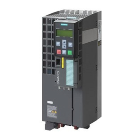
Description 3.3 Power Module Power Module Important data on the Power Modules is provided in this section. Further information is contained in the Hardware Installation Manual of the Power Module. Overview of the manuals (Page 507) All power data refers to rated values or to power for operation with low overload (LO). Which Power Module can I use with the Control Unit? Table 3- 5 Permitted combinations of Control Unit and Power Module... - Page 32 Description 3.3 Power Module Image 3-3 Examples of Power Modules with Push Through technology FSA … FSC PM230, 3 AC 400 V - pump and fan applications The PM230 Power Module is available without a filter or with integrated class A line filter. Article number range: 6SL3210-1NE…...
- Page 33 Description 3.3 Power Module 3-phase 600 VAC Article number range: 6SL3210-1PH… • IP20: 6SL3211-1PH… • Push Through: Frame size Power range (kW), IP20 11 … 37 45 … 55 75 … 132 Power range (kW), PT PM240, 3 AC 400 V - for standard applications The PM240 Power Module is available without a filter or with an integrated class A line filter with degree of protection IP20.
-
Page 34: Power Module In Ip55 Degree Of Protection / Ul Type 12
Description 3.4 Components for the Power Modules 3.3.2 Power Module in IP55 degree of protection / UL Type 12 PM230, 3 AC 400 V, degree of protection IP55 / UL Type 12 Frame size Power range (kW) Filter Class A 0.37 …... -
Page 35: Components For The Power Modules
Description 3.4 Components for the Power Modules Components for the Power Modules 3.4.1 Accessories for installation and shielding Shield connection kit Establish the shield and strain relief for the power con- nections using the shield connection kit. The shield connection kit comprises a shield plate and serrated strips with screws. -
Page 36: Line Filter
Description 3.4 Components for the Power Modules 3.4.2 Line filter With a line filter, the inverter can achieve a higher radio interference class. An external filter is not required for inverters with integrated line filter. Adjacent examples of line filters. The line filter corresponds to Class A or B according to EN55011: 2009. - Page 37 Description 3.4 Components for the Power Modules External line filters for PM250 Power Module Power Line filter, class B 6SL3225-0BE25-5AA0, 7.5 kW … 15.0 kW 6SL3203-0BD23-8SA0 6SL3225-0BE27-5AA0, 6SL3225-0BE31-1AA0 Converter with the CU240B-2 and CU240E-2 Control Units Operating Instructions, 01/2016, FW V4.7 SP6, A5E34259001B AC...
-
Page 38: Line Reactor
Description 3.4 Components for the Power Modules 3.4.3 Line reactor The line reactor supports the overvoltage protection, smoothes the harmonics in the line supply and bridges commutation dips. For the Power Modules subsequent- ly listed, a line reactor is suitable in order to dampen the specified effects. - Page 39 Description 3.4 Components for the Power Modules Line reactors for PM240-2, 200 V Power Module Power Line reactor 6SL3210-1PB13-0☐L0, 0.55 kW … 0.75 kW 6SL3203-0CE13-2AA0 6SL3210-1PB13-8☐L0 6SL3210-1PB15-5☐L0, 1.1 kW … 2.2 kW 6SL3203-0CE21-0AA0 6SL3210-1PB17-4☐L0, 6SL321☐-1PB21-0☐L0 6SL3210-1PB21-4☐L0, 3 kW … 4 kW 6SL3203-0CE21-8AA0 6SL321☐-1PB21-8☐L0 6SL321☐-1PC22-2☐L0,...
-
Page 40: Output Reactor
Description 3.4 Components for the Power Modules 3.4.4 Output reactor Output reactors reduce the voltage stress on the motor windings and the load placed on the inverter as a result of capacitive recharging currents in the cables. An output reactor is required for shielded motor cables longer than 50 m or unshielded motor cables longer than 100 m. - Page 41 Description 3.4 Components for the Power Modules Power Module Power Output reactor 6SL3224-0XE41-3UA0 160 kW 6SL3000-2BE33-2AA0 6SL3224-0XE41-6UA0 200 kW 6SL3000-2BE33-8AA0 6SL3224-0XE42-0UA0 250 kW 6SL3000-2BE35-0AA0 Output reactors for PM250 Power Module Power Module Power Output reactor 6SL3225-0BE25-5☐A0, 7.5 kW … 15.0 kW 6SL3202-0AJ23-2CA0 6SL3225-0BE27-5☐A0, 6SL3225-0BE31-1☐A0...
- Page 42 Description 3.4 Components for the Power Modules Output reactors for PM230 push-through Power Modules Power Module Power Output reactor 6SL3211-1NE17-7☐L0 3.0 kW 6SL3202-0AE18-8CA0 6SL3211-1NE21-8☐L0 7.5 kW 6SL3202-0AE21-8CA0 6SL3211-1NE23-8☐L0 18.5 kW 6SL3202-0AE23-8CA0 Output reactors for PM240-2 Power Module, 200 V Power Module Power Output reactor 6SL3210-1PB13-0☐L0,...
-
Page 43: Sine-Wave Filter
Description 3.4 Components for the Power Modules 3.4.5 Sine-wave filter The sine-wave filter at the inverter output limits the voltage rate-of-rise and the peak voltages at the motor winding. The maximum permissible length of motor feeder cables is increased to 300 m. The following applies when using a sine-wave filter: •... - Page 44 Description 3.4 Components for the Power Modules Sine-wave filter for PM250 Power Module Power Module Power Sine-wave filter 6SL3225-0BE25-5☐A0 7.5 kW 6SL3202-0AE22-0SA0 6SL3225-0BE27-5☐ A0, 11.0 kW … 15.0 kW 6SL3202-0AE23-3SA0 6SL3225-0BE31-1☐A0 6SL3225-0BE31-5☐A0, 18.5 kW … 22 kW 6SL3202-0AE24-6SA0 6SL3225-0BE31-8☐A0 6SL3225-0BE32-2☐A0 30 kW 6SL3202-0AE26-2SA0 6SL3225-0BE33-0☐A0,...
-
Page 45: Braking Resistor
Description 3.4 Components for the Power Modules 3.4.6 Braking resistor The braking resistor allows loads with a high moment of inertia to be quickly braked. The Power Module controls the braking resistor via its integrated braking module. Adjacent, as example, a braking resistor for PM240 and PM340 Power Modules, frame size FSA, which can be mounted below the device. - Page 46 Description 3.4 Components for the Power Modules Braking resistors for PM240-2, 200 V Power Module Power Braking resistor 6SL3210-1PB13-0❒L0, 0.55 kW … 0.75 kW JJY:023146720008 6SL321❒-1PB13-8❒L0 6SL3210-1PB15-5❒L0, 1.1 kW … 2.2 kW JJY:023151720007 6SL3210-1PB17-4❒L0, 6SL321❒-1PB21-0❒L0 6SL3210-1PB21-4❒L0, 3 kW … 4 kW JJY:02 3163720018 6SL321❒-1PB21-8❒L0 6SL3210-1PC22-2❒L0,...
- Page 47 Description 3.4 Components for the Power Modules Braking resistors for PM240-2, 690 V Power Module Power Braking resistor 6SL3210-1PH21-4❒L0, 11 kW … 37 kW JJY:023424020002 6SL3210-1PH22-0❒L0, 6SL3210-1PH22-3❒L0, 6SL3210-1PH22-7❒L0, 6SL3210-1PH23-5❒L0, 6SL3210-1PH24-2❒L0 6SL3210-1PH25-2❒L0, 45 kW … 55 kW JJY:023434020002 6SL3210-1PH26-2❒L0 6SL3210-1PH28-0❒L0, 75 kW … 90 kW JJY:023464020002 6SL3210-1PH31-0❒L0 6SL3210-1PH31-2❒L0,...
-
Page 48: Brake Relay
Description 3.4 Components for the Power Modules 3.4.7 Brake Relay The brake relay has a switch contact (NO contact) to control the motor brake coil. Article number: 6SL3252-0BB00-0AA0 3.4.8 Safe Brake Relay The Safe Brake Relay controls a 24 V motor brake and monitors the brake control for a short-circuit or interrupted cable. -
Page 49: Supported Motor Series
Description 3.5 Supported motor series Supported motor series Supported motors The inverter is designed for the following motor series: SIMOTICS GP, SIMOTICS SD IEC motors SIMOTICS M main motors 1LG6, 1LA7, 1LA9, 1LE1 and 1PC1 standard 1PH8 induction motors induction motors SIMOTICS S 1FK7 permanent-magnet synchro- SIMOTICS 1FG1 geared synchronous motors nous motors without encoder... - Page 50 IEC. Further information is provided in the Internet: Multi-motor drive (http://support.automation.siemens.com/WW/view/en/84049346) For installations in compliance with UL, multi-motor drive operation is not permissible. Converter with the CU240B-2 and CU240E-2 Control Units...
-
Page 51: Tools To Commission The Inverter
DVD article number STARTER: 6SL3072-0AA00-0AG0 Startdrive: 6SL3072-4CA02-1XG0 System requirements and download: STARTER (http://support.automation.siemens.com/WW/view/en/26233208) Startdrive (http://support.automation.siemens.com/WW/view/en/68034568) Help regarding operation: STARTER videos (http://www.automation.siemens.com/mcms/mc-drives/en/low-voltage- inverter/sinamics-g120/videos/Pages/videos.aspx) Startdrive tutorial (http://support.automation.siemens.com/WW/view/en/73598459) Converter with the CU240B-2 and CU240E-2 Control Units Operating Instructions, 01/2016, FW V4.7 SP6, A5E34259001B AC... - Page 52 Description 3.6 Tools to commission the inverter Converter with the CU240B-2 and CU240E-2 Control Units Operating Instructions, 01/2016, FW V4.7 SP6, A5E34259001B AC...
-
Page 53: Installing
Installing Overview of the inverter installation Installing the inverter Precondition Before installation, please check: ● Are the required inverter components available? – Power Module – Control Unit – Accessories, e.g. line reactor or braking resistor ● Do you have the necessary tools and small parts/components required to install the inverter? Procedure To install the inverter, proceed as follows:... -
Page 54: Connecting Inverters In Compliance With Emc
Installing 4.2 Connecting inverters in compliance with EMC Connecting inverters in compliance with EMC 4.2.1 EMC-compliant connection of the converter EMC-compliant installation of the inverter and motor are required in order to ensure disturbance-free operation of the drive. Install and operate inverters with IP20 degree of protection in a closed control cabinet. Inverters with degree of protection IP55 are suitable for installation outside a control cabinet. - Page 55 Installing 4.2 Connecting inverters in compliance with EMC ● For screw connections onto painted or anodized surfaces, establish a good conductive contact using one of the following methods: – Use special (serrated) contact washers that cut through the painted or anodized surface.
- Page 56 ● Only use metallic or metallized connectors for the plug connections for shielded data cables (e.g. PROFIBUS connection). Further information You can find additional information about the EMC installation guidelines under (http://support.automation.siemens.com/WW/view/en/60612658): Converter with the CU240B-2 and CU240E-2 Control Units Operating Instructions, 01/2016, FW V4.7 SP6, A5E34259001B AC...
-
Page 57: Laying Emc-Compliant Cables
Installing 4.2 Connecting inverters in compliance with EMC 4.2.3 Laying EMC-compliant cables Rules for cable installation to ensure EMC ● Use shielded cables for the following connections: – Motor and motor temperature sensor – Braking resistor (not available for all inverters) –... -
Page 58: Installing Reactors, Filters And Braking Resistors
Installing 4.3 Installing reactors, filters and braking resistors Installing reactors, filters and braking resistors Installing reactors, filters and braking resistors The following supplementary components may be required depending on the Power Modules and the particular application: ● Line reactors ● Filter ●... - Page 59 Installing 4.3 Installing reactors, filters and braking resistors Converter with the CU240B-2 and CU240E-2 Control Units Operating Instructions, 01/2016, FW V4.7 SP6, A5E34259001B AC...
-
Page 60: Installing Power Modules
Installing 4.4 Installing Power Modules Installing Power Modules 4.4.1 Basic installation rules Installing Power Modules The following is required to correctly install a Power Module: ● Install the Power Module in a control cabinet. ● Install the Power Module vertically with the line and motor connections facing downwards. ●... - Page 61 Installing 4.4 Installing Power Modules Procedure Proceed as follows to correctly install the Power Module: 1. Prepare the cutout and the mounting holes for the Power Module and the mounting frame corresponding to the dimensioned drawings of the mounting frame. Also note that the PT Power Modules must be vertically mounted with the line and motor connections facing downwards.
-
Page 62: Dimensioned Drawings, Drilling Dimensions For The Pm240-2 Power Module, Ip20
Installing 4.4 Installing Power Modules 4.4.2 Dimensioned drawings, drilling dimensions for the PM240-2 Power Module, IP20 The following dimensioned drawings and drilling patterns are not to scale. Table 4- 1 Mounting dimensions Frame size Width Height (mm) Depth (mm) (mm) Total Shield plate Power... - Page 63 Installing 4.4 Installing Power Modules Depth with Control Unit and Operator Panel FSA … FSC: + 41 mm • with Control Unit: + 52 mm • With Control Unit and blanking cover / BOP-2: + 63 mm • With Control Unit and IOP: FSD …...
-
Page 64: Dimensioned Drawings, Drilling Dimensions For The Pm240-2 Power Module, Pt
Installing 4.4 Installing Power Modules 4.4.3 Dimensioned drawings, drilling dimensions for the PM240-2 Power Module, PT inverter The following dimensioned drawings and drilling patterns are not to scale. Table 4- 3 Mounting dimensions Frame size Width Height (mm) Depth (mm) (mm) with shield plate 117.7... - Page 65 Installing 4.4 Installing Power Modules Table 4- 4 Drilling dimensions, cooling clearances and fixing Frame size Drilling dimensions and dimensions for Cooling air clearances Fixing the control cabinet cutout (mm) (mm) Bottom Front 8 x M5 / 3.5 147.5 34.5 8 x M5 / 3.5 30.5 10 x M5 / 3.5...
-
Page 66: Dimensioned Drawings, Drilling Dimensions For The Pm240 Power Module, Fsa
Installing 4.4 Installing Power Modules 4.4.4 Dimensioned drawings, drilling dimensions for the PM240 Power Module, FSA … FSF The following dimensioned drawings and drilling patterns are not to scale. Table 4- 5 Mounting dimensions Frame size Width (mm) Height (mm) Depth (mm) with shield connection kit FSB without/with filter... - Page 67 Installing 4.4 Installing Power Modules Depth with Control Unit and Operator Panel + 41 mm • with Control Unit: + 52 mm • With Control Unit and blanking cover / BOP-2: • With Control Unit and IOP: + 63 mm Table 4- 6 Drilling dimensions, cooling clearances and fixing Frame size...
-
Page 68: Dimensioned Drawings, Drilling Dimensions For The Pm240 Power Module, Fsgx
Installing 4.4 Installing Power Modules 4.4.5 Dimensioned drawings, drilling dimensions for the PM240 Power Module, FSGX Mount the Power Module with the following clearances to other devices: ● Top: 250 mm ● Bottom: 150 mm ● Lateral: no clearance required for thermal reasons. Fasten the Power Module with six M8 screws with a tightening torque of 13 Nm. -
Page 69: Dimensioned Drawings, Drilling Dimensions For The Pm230 Power Module, Ip20
Installing 4.4 Installing Power Modules 4.4.6 Dimensioned drawings, drilling dimensions for the PM230 Power Module, IP20 The following dimensioned drawings and drilling patterns are not to scale. Table 4- 7 Mounting dimensions Frame size Width (mm) Height (mm) Depth (mm) with shield plate FSB without/with filter FSC without/with filter... - Page 70 Installing 4.4 Installing Power Modules Depth with Control Unit and Operator Panel + 41 mm • with Control Unit: + 52 mm • With Control Unit and blanking cover / BOP-2: • With Control Unit and IOP: + 63 mm Table 4- 8 Drilling dimensions, cooling clearances and fixing Frame size...
-
Page 71: Dimensioned Drawings, Drilling Dimensions For The Pm230 Power Module, Pt Inverter
Installing 4.4 Installing Power Modules 4.4.7 Dimensioned drawings, drilling dimensions for the PM230 Power Module, PT inverter The following dimensioned drawings and drilling patterns are not to scale. Table 4- 9 Mounting dimensions Frame size Width Height (mm) Depth (mm) (mm) with shield plate... - Page 72 Installing 4.4 Installing Power Modules Table 4- 10 Drilling dimensions, cooling clearances and fixing Frame size Drilling dimensions and dimensions for Cooling air clearances Fixing the control cabinet cutout (mm) (mm) Bottom Front 8 x M5 / 3.5 147.5 34.5 8 x M5 / 3.5 30.5 10 x M5 / 3.5...
-
Page 73: Dimensioned Drawings, Drilling Dimensions For The Pm250 Power Module
Installing 4.4 Installing Power Modules 4.4.8 Dimensioned drawings, drilling dimensions for the PM250 Power Module The following dimensioned drawings and drilling patterns are not to scale. Table 4- 11 Mounting dimensions Frame size Width (mm) Height (mm) Depth (mm) with shield connection kit FSC without/with filter FSD without filter FSD with filter... - Page 74 Installing 4.4 Installing Power Modules Depth with Control Unit and Operator Panel + 41 mm • with Control Unit: + 52 mm • With Control Unit and blanking cover / BOP-2: • With Control Unit and IOP: + 63 mm Table 4- 12 Drilling dimensions, cooling clearances and fixing Frame size...
-
Page 75: Dimensioned Drawings, Drilling Dimensions For The Pm260 Power Module
The dimensioned drawings and drilling dimensions for the PM260 Power Module are available in the Internet: Installation Guide for the PM260 Power Module (https://support.industry.siemens.com/cs/ww/en/view/79109730) Converter with the CU240B-2 and CU240E-2 Control Units Operating Instructions, 01/2016, FW V4.7 SP6, A5E34259001B AC... -
Page 76: Dimensioned Drawings, Drilling Dimensions For The Pm340 Power Module
Installing 4.4 Installing Power Modules 4.4.10 Dimensioned drawings, drilling dimensions for the PM340 Power Module The following dimensioned drawings and drilling patterns are not to scale. Image 4-1 Mounting dimensions and drilling dimensions (mm) The Power Modules can be mounted and operated side-by-side. For tolerance reasons, we recommend a lateral clearance of approx. -
Page 77: Connecting The Line Supply, Motor, And Inverter Components
Installing 4.5 Connecting the line supply, motor, and inverter components Connecting the line supply, motor, and inverter components 4.5.1 Permissible line supplies Note Restrictions for installation altitudes above 2000 m Above an installation altitude of 2000 m, the permissible line supplies are restricted. Restrictions for special ambient conditions (Page 475) Note Line requirement... - Page 78 Installing 4.5 Connecting the line supply, motor, and inverter components TN line system A TN line system transfers the PE protective conductor to the installed plant or system using a cable. Generally, in a TN line system the neutral point is grounded. There are versions of a TN system with a grounded line conductor, e.g.
- Page 79 Installing 4.5 Connecting the line supply, motor, and inverter components TT line system In a TT line system, the transformer grounding and the installation grounding are independent of one another. There are TT systems with and without transfer of the neutral conductor N. Inverter operated on a TT line system ●...
-
Page 80: Dimensioning The Protective Conductor
Installing 4.5 Connecting the line supply, motor, and inverter components IT system In an IT line system, all of the conductors are insulated with respect to the PE protective conductor – or connected to the PE protective conductor through an impedance. There are IT systems with and without transfer of the neutral conductor N. - Page 81 Installing 4.5 Connecting the line supply, motor, and inverter components Laying the protective conductor ① For the protective conductor of the line-system connection within a machine or system, the follow- ing applies: 1. Observe the local regulations for protective conductors subject to an increased leakage cur- rent at the site of operation.
-
Page 82: Connecting The Inverter
Installing 4.5 Connecting the line supply, motor, and inverter components 4.5.3 Connecting the inverter Image 4-5 Connecting the PM230 IP20 and push-through Power Module Image 4-6 Connecting the PM240, PM240-2 IP20 and push-through Power Modules Converter with the CU240B-2 and CU240E-2 Control Units Operating Instructions, 01/2016, FW V4.7 SP6, A5E34259001B AC... - Page 83 Installing 4.5 Connecting the line supply, motor, and inverter components Image 4-7 Connecting the PM250 Power Module Image 4-8 Connecting the PM260 Power Module Image 4-9 Connecting the PM240-2 and PM340 1AC Power Modules Converter with the CU240B-2 and CU240E-2 Control Units Operating Instructions, 01/2016, FW V4.7 SP6, A5E34259001B AC...
- Page 84 Installing 4.5 Connecting the line supply, motor, and inverter components DANGER Danger to life as a result of a hazardous voltage at the motor connections As soon as the inverter is connected to the line supply, the motor connections of the inverter may carry dangerous voltages.
- Page 85 Before you connect the motor, ensure that the motor has the appropriate connection for your application: Motor is connected in the star or delta configuration With SIEMENS motors, you will see a diagram of both connection methods on the inside of the cover of the terminal box: •...
-
Page 86: Connecting A Motor Holding Brake
Installing 4.5 Connecting the line supply, motor, and inverter components 4.5.4 Connecting a motor holding brake The inverter uses the Brake Relay to control the motor holding brake. Two types of Brake Relay exist: ● The Brake Relay controls the motor holding brake ●... -
Page 87: Mounting And Connecting The Brake Relay
Installing 4.5 Connecting the line supply, motor, and inverter components 4.5.4.1 Mounting and connecting the Brake Relay The Brake Relay must be connected to the protective conductor if the motor brake is supplied from a PELV circuit. 4.5.4.2 Mounting and connecting the Safe Brake Relay The Safe Brake Relay must be connected to the protective conductor if the motor brake is supplied from a PELV circuit. -
Page 88: Technical Data Of The Brake Relay
Installing 4.5 Connecting the line supply, motor, and inverter components 4.5.4.3 Technical data of the brake relay? Brake Relay Safe Brake Relay 6SL32520BB000AA0 6SL32520BB010AA0 Input voltage via the Power Module 20.4 ... 28.8 VDC Input current via the Power Module Max. -
Page 89: Install And Connect The Brake Relay - Pm240-2 Power Module
Installing 4.5 Connecting the line supply, motor, and inverter components 4.5.4.5 Install and connect the Brake Relay - PM240-2 Power Module Installing the Brake Relay ● FSA … FSC: Install the Brake Relay next to the Power Module. ● FSD … FSF: Install the Brake Relay at the rear of the lower shield plate. Attach the Brake Relay before you install the shield plate. -
Page 90: Installing Control Unit
Installing 4.6 Installing Control Unit Installing Control Unit Installing the Control Unit - General Each Power Module has an appropriate holder for the Control Unit and a release mechanism. Inserting the Control Unit Proceed as follows to plug the Control Unit onto a Power Module: 1. -
Page 91: Overview Of The Interfaces
Installing 4.6 Installing Control Unit 4.6.1 Overview of the interfaces Interfaces at the front of the Control Unit To access the interfaces at the front of the Control Unit, you must lift the Operator Panel (if one is being used) and open the front doors. ①... -
Page 92: Fieldbus Interface Allocation
Installing 4.6 Installing Control Unit 4.6.2 Fieldbus interface allocation Interfaces at the lower side of the CU240B-2 and CU240E-2 Control Units Converter with the CU240B-2 and CU240E-2 Control Units Operating Instructions, 01/2016, FW V4.7 SP6, A5E34259001B AC... -
Page 93: Terminal Strips On Cu240B-2 Control Units
Installing 4.6 Installing Control Unit 4.6.3 Terminal strips on CU240B-2 Control Units Terminal strips with wiring example All terminals labelled with reference potential "GND" are connected internally in the inverter. Reference potential "DI COM" is electrically isolated from "GND". → If, as shown above, the 24 V supply from terminal 9 is used to supply the digital inputs, then you must connect "GND"... - Page 94 Installing 4.6 Installing Control Unit Additional options for wiring the digital inputs You must remove the jumper between terminals 28 and 69 if it is necessary to have electrical isolation between the exter- nal power supply and the internal inverter power supply.
-
Page 95: Factory Setting Of The Cu240B-2 Interfaces
Installing 4.6 Installing Control Unit 4.6.3.1 Factory setting of the CU240B-2 interfaces Factory setting of the terminal strip on the CU240B-2 The factory setting of the terminals depends on whether the Control Unit has a PROFIBUS / PROFINET interface. Control Units with USS interface The fieldbus interface is not active. - Page 96 Installing 4.6 Installing Control Unit Control Units with PROFIBUS interface The function of the fieldbus interface and digital inputs DI 0, DI 1 depends on DI 3. --- No function. DO 0: p0730 AO 0: p0771[0] DI x: r0722.x Speed setpoint (main setpoint): p1070[0] = 2050[1] Image 4-12 Factory setting of the CU240B-2 DP and CU240B-2 PN Control Units Changing the function of the terminals...
-
Page 97: Default Settings Of The Cu240B-2 Interfaces
Installing 4.6 Installing Control Unit 4.6.3.2 Default settings of the CU240B-2 interfaces Default setting 7: "Fieldbus with data set switchover" Factory setting for inverters with PROFIBUS interface DO 0: p0730 AO 0: p0771[0] DI 0: r0722.0, …, DI 3: r0722.3 Speed setpoint (main setpoint): p1070[0] = 2050[1] Jog 1 speed setpoint: p1058, factory setting: 150 rpm Jog 2 speed setpoint: p1059, factory setting: -150 rpm... - Page 98 Installing 4.6 Installing Control Unit Default setting 12: "Standard I/O with analog setpoint" Factory setting for inverters with USS interface DO 0: p0730 AO 0: p0771[0] DI 0: r0722.0, …, DI 2: r0722.2 AI 0: r0755[0] Speed setpoint (main setpoint): p1070[0] = 755[0] Designation in the BOP-2: Std ASP Default setting 17: "2-wire (forw/backw1)"...
- Page 99 Installing 4.6 Installing Control Unit Default setting 19: "3-wire (enable/forw/backw)" DO 0: p0730 AO 0: p0771[0] DI 0: r0722.0, …, DI 3: r0722.3 AI 0: r0755[0] Speed setpoint (main setpoint): p1070[0] = 755[0] Designation in the BOP-2: 3-wIrE 1 Default setting 20: "3-wire (enable/on/reverse)" DO 0: p0730 AO 0: p0771[0] DI 0: r0722.0, …, DI 3: r0722.3...
-
Page 100: Terminal Strips On Cu240E-2 Control Units
Installing 4.6 Installing Control Unit 4.6.4 Terminal strips on CU240E-2 Control Units Terminal strips with wiring example All terminals labelled with reference potential "GND" are connected internally in the inverter. Reference potentials "DI COM1" and "DI COM2" are electrically isolated from "GND". →... - Page 101 Installing 4.6 Installing Control Unit Additional options for wiring the digital inputs If you wish to connect the potential of an external power supply with the po- tential of the internal inverter power supply, then you must connect "GND" with terminals 34and 69. Connecting P-switching contacts with an external power supply Connect terminals 69 and 34 with one...
-
Page 102: Factory Setting Of The Cu240E-2 Interfaces
Installing 4.6 Installing Control Unit 4.6.4.1 Factory setting of the CU240E-2 interfaces Factory setting of the terminal strip on the CU240E-2 The factory setting of the terminal strip depends on the Control Unit. Control Units with USS interface The fieldbus interface is not active. --- No function. - Page 103 Installing 4.6 Installing Control Unit Control Units with PROFIBUS or PROFINET interface The function of the fieldbus interface and digital inputs DI 0, DI 1 depends on DI 3. --- No function. DO x: p073x AO 0: p0771[0] DI x: r0722.x Speed setpoint (main setpoint): p1070[0] = 2050[1] Image 4-15 Factory setting of the CU240E-2 DP(-F) and CU240E-2 PN(-F) Control Units...
-
Page 104: Default Settings Of The Cu240E-2 Interfaces
Installing 4.6 Installing Control Unit 4.6.4.2 Default settings of the CU240E-2 interfaces Default setting 1: "Conveyor technology with 2 fixed frequencies" DO 0: p0730, DO 1: p0731 AO 0: p0771[0], AO 1: p0771[1] DI 0: r0722.0, …, DI 5: r0722.5 Fixed speed setpoint 3: p1003, fixed speed setpoint 4: p1004, fixed speed setpoint active: r1024 Speed setpoint (main setpoint): p1070[0] = 1024 DI 4 and DI 5 = high: The inverter adds both fixed speed setpoints... - Page 105 Installing 4.6 Installing Control Unit Default setting 3: "Conveyor technology with 4 fixed frequencies" DO 0: p0730, DO 1: p0731 AO 0: p0771[0], AO 1: p0771[1] DI 0: r0722.0, …, DI 5: r0722.5 Fixed speed setpoint 1: p1001, … fixed speed setpoint 4: p1004, fixed speed setpoint active: r1024 Speed setpoint (main setpoint): p1070[0] = 1024 Several DI 0, DI 1, DI 4 and DI 5 = high: The inverter adds the corresponding fixed speed setpoints.
- Page 106 Installing 4.6 Installing Control Unit Default setting 5: "Conveyor systems with fieldbus and Basic Safety" DO 0: p0730, DO 1: p0731 AO 0: p0771[0], AO 1: p0771[1] DI 4: r0722.4, DI 5: r0722.5 Speed setpoint (main setpoint): p1070[0] = 2050[1] Designation in the BOP-2: coN Fb S Default setting 6: "Fieldbus with Extended Safety"...
- Page 107 Installing 4.6 Installing Control Unit Default setting 7: "Fieldbus with data set switchover" Factory setting for inverters with PROFIBUS or PROFINET interface DO 0: p0730, DO 1: p0731 AO 0: p0771[0], AO 1: p0771[1] DI 0: r0722.0, …, DI 3: r0722.3 Speed setpoint (main setpoint): p1070[0] = 2050[1] Jog 1 speed setpoint: p1058, factory setting: 150 rpm Jog 2 speed setpoint: p1059, factory setting: -150 rpm...
- Page 108 Installing 4.6 Installing Control Unit Default setting 8: "MOP with Basic Safety" DO 0: p0730, DO 1: p0731 AO 0: p0771[0], AO 1: p0771[1] DI 0: r0722.0, …, DI 5: r0722.5 Motorized potentiometer setpoint after ramp-function generator: r1050 Speed setpoint (main setpoint): p1070[0] = 1050 Designation in the BOP-2: MoP SAFE Default setting 9: "Standard I/O with MOP"...
- Page 109 Installing 4.6 Installing Control Unit Default setting 12: "Standard I/O with analog setpoint" DO 0: p0730, AO 0: p0771[0], AO 1: p0771[1] DI 0: r0722.0, …, DI 2: r0722.2 AI 0: r0755[0] DO 1: p0731 Speed setpoint (main setpoint): p1070[0] = 755[0] Designation in the BOP-2: Std ASP Default setting 13: "Standard I/O with analog setpoint and safety"...
- Page 110 Installing 4.6 Installing Control Unit Default setting 14: "Process industry with fieldbus" PROFIdrive telegram 20 MOP = motorized potentiometer DO 0: p0730, DO 1: p0731 AO 0: p0771[0], AO 1: p0771[1] DI 0: r0722.0, …, DI 5: r0722.5 Motorized potentiometer setpoint after ramp-function generator: r1050 Speed setpoint (main setpoint): p1070[0] = 2050[1], p1070[1] = 1050 Designation in the BOP-2: Proc Fb Converter with the CU240B-2 and CU240E-2 Control Units...
- Page 111 Installing 4.6 Installing Control Unit Default setting 15: "Process industry" DO 0: p0730, AO 0: p0771[0], AO 1: p0771[1] DI 0: r0722.5, …, DI 4: r0722.5 AI 0: r0755[0] DO 1: p0731 Motorized potentiometer setpoint after ramp-function generator: r1050 Speed setpoint (main setpoint): p1070[0] = 755[0], p1070[1] = 1050 Designation in the BOP-2: Proc Default setting 17: "2-wire (forw/backw1)"...
- Page 112 Installing 4.6 Installing Control Unit Default setting 18: "2-wire (forw/backw2)" DO 0: p0730, AO 0: p0771[0], AO 1: p0771[1] DI 0: r0722.0, …, DI 2: r0722.2 AI 0: r0755[0] DO 1: p0731 Speed setpoint (main setpoint): p1070[0] = 755[0] Designation in the BOP-2: 2-wIrE 2 Default setting 19: "3-wire (enable/forw/backw)"...
- Page 113 Installing 4.6 Installing Control Unit Default setting 20: "3-wire (enable/on/reverse)" DO 0: p0730, AO 0: p0771[0], AO 1: p0771[1] DI 0: r0722.0, …, DI 4: r0722.4 AI 0: r0755[0] DO 1: p0731 Speed setpoint (main setpoint): p1070[0] = 755[0] Designation in the BOP-2: 3-wIrE 2 Default setting 21: "USS fieldbus"...
-
Page 114: Safety Input
Installing 4.6 Installing Control Unit 4.6.4.3 Safety input Which devices are you allowed to connect? The safety-related input is designed for the following devices: ● Connection of safety sensors, e.g. emergency stop command devices or light curtains. ● Connection of pre-processing devices, e.g. fail-safe control systems and safety relays. Signal state The inverter expects signals with the same state at its safety-related input: ●... -
Page 115: Wiring The Terminal Strip
"External fault" function. You can find additional information about the temperature monitoring relay on the Internet: Manual 3RS1 / 3RS2 temperature monitoring relays (https://support.industry.siemens.com/cs/ww/en/view/54999309) Note If your application requires UL certification, please note that the power supply of the digital output must comply with specific specifications. -
Page 116: Monitoring The Temperature Of The Braking Resistor
Further information about EMC-compliant wiring is available on the Internet: EMC installation guideline (http://support.automation.siemens.com/WW/view/en/60612658) ● Use the shield connection plate of the Control Unit as strain relief. Overview of Control Units (Page 29) 4.6.6... - Page 117 Installing 4.6 Installing Control Unit Procedure Proceed as follows to monitor the braking resistor temperature: 1. Connect the temperature monitoring system of the braking resistor (terminals T1 and T2 on the braking resistor) to a free digital input on the inverter. Image 4-16 Example: Temperature monitoring of the braking resistor via digital input DI 3 on the Control Unit...
-
Page 118: Connecting The Inverter To The Fieldbus
Installing 4.7 Connecting the inverter to the fieldbus Connecting the inverter to the fieldbus Fieldbus interfaces of the Control Units The Control Units are available in different versions for communication with higher-level controls with the subsequently listed fieldbus interfaces: Fieldbus Profiles S7 communi- Control Unit... -
Page 119: Profinet
Installing 4.7 Connecting the inverter to the fieldbus 4.7.1 PROFINET You can either communicate via Ethernet using the inverter, or integrate the inverter in a PROFINET network. The inverter as Ethernet node Image 4-17 The inverter as Ethernet node The inverter in PROFINET IO operation Image 4-18 The inverter in PROFINET IO operation In PROFINET IO operation, the inverter supports the following functions:... -
Page 120: What Do You Need For Communication Via Profinet
● Shared Device for Control Units with fail-safe functions General information about PROFINET You can find general information about PROFINET in the Internet: ● General information about PROFINET: Industrial Communication (http://www.automation.siemens.com/mcms/automation/en/industrial- communications/profinet/Pages/Default.aspx). ● Configuring the functions: PROFINET system description (http://support.automation.siemens.com/WW/view/en/19292127). -
Page 121: Integrating Inverters Into Profinet
● Install the GSDML of the inverter using “Tools/Install GSDML file" in HW Config. Further information is provided in the Fieldbus function manual. Overview of the manuals (Page 507) Configuring the communication with a non-Siemens control 1. Import the device file (GSDML) of the inverter into the engineering tool for your control system. -
Page 122: Installing Gsdml
Set p0804 = 12. The inverter writes the GSDML as zipped file (*.zip) into directory /SIEMENS/SINAMICS/DATA/CFG on the memory card. 2. Unzip the GSDML file to a folder on your computer. 3. Import the GSDML into the configuring tool of your control system. -
Page 123: Profibus
General information on PROFIBUS DP can be found in the Internet: ● PROFIBUS user organization (http://www.profibus.com/downloads/installation-guide/) ● Information about PROFIBUS DP (http://www.automation.siemens.com/net/html_76/support/printkatalog.htm) 4.7.2.1 What do you need for communication via PROFIBUS? Check the communication settings using the following table. If you answer "Yes" to the questions, you have correctly set the communication settings and can control the inverter via the fieldbus. -
Page 124: Integrating Inverters Into Profibus
Installing 4.7 Connecting the inverter to the fieldbus 4.7.2.2 Integrating inverters into PROFIBUS Procedure To connect the inverter to a control via PROFIBUS DP, proceed as follows: 1. Integrate the inverter into the bus system (e.g. line topology) of the control using PROFIBUS cables via socket X126. -
Page 125: Installing The Gsd
– or from your inverter. To do this, insert a memory card into the inverter and set p0804 = 12. In this way, you will save the GSD on the memory card as (DPGSD.ZIP) compressed file in the directory /SIEMENS/SINAMICS/DATA/CFG . 2. Unzip the GSDfile in a folder on your computer. - Page 126 Installing 4.7 Connecting the inverter to the fieldbus 3. Wait until all LEDs on the inverter go dark. 4. Switch on the inverter supply voltage again. Your settings become active after switching on. You have now changed the bus address. Converter with the CU240B-2 and CU240E-2 Control Units Operating Instructions, 01/2016, FW V4.7 SP6, A5E34259001B AC...
-
Page 127: Commissioning
Commissioning Commissioning guidelines Overview 1. Define the requirements to be met by the drive for your application. (Page 128) 2. Restore the factory settings of the inverter if necessary. (Page 162) 3. Check if the factory setting of the inverter is sufficient for your application. -
Page 128: Preparing For Commissioning
Commissioning 5.2 Preparing for commissioning Preparing for commissioning 5.2.1 Collecting motor data Before starting commissioning, you must know the following data: ● Which motor is connected to the inverter? Note down the Article No. of the motor and the motor’s nameplate data. If available, note down the motor code on the motor’s nameplate. -
Page 129: Inverter Factory Setting
Commissioning 5.2 Preparing for commissioning 5.2.2 Inverter factory setting Motor In the factory, the inverter is set for an induction motor matching the rated power of the Power Module. Inverter control You can find the factory settings for the inverter control in the following Chapters: Inverter interfaces The inputs and outputs and the fieldbus interface of the inverter have specific functions when set to the factory settings. - Page 130 Commissioning 5.2 Preparing for commissioning The ramp-up and ramp-down times define the maximum motor acceleration when the speed setpoint changes. The ramp-up and ramp-down time is the time between motor standstill and the maximum speed, or between the maximum speed and motor standstill. Traverse the motor in the jog mode For an inverter with PROFIBUS or PROFINET interface, operation can be switched over using digital input DI 3.
-
Page 131: Quick Commissioning Using The Bop-2 Operator Panel
Commissioning 5.3 Quick commissioning using the BOP-2 operator panel Quick commissioning using the BOP-2 operator panel 5.3.1 Inserting the BOP-2 Plugging on an operator panel Procedure To plug an Operator Panel on the Control Unit, proceed as follows: 1. Locate the lower edge of the Operator Panel into the matching recess of the Control Unit. -
Page 132: Overview
Commissioning 5.3 Quick commissioning using the BOP-2 operator panel 5.3.2 Overview Image 5-3 Quick commissioning using the BOP-2 operator panel Converter with the CU240B-2 and CU240E-2 Control Units Operating Instructions, 01/2016, FW V4.7 SP6, A5E34259001B AC... -
Page 133: Starting Quick Commissioning
Commissioning 5.3 Quick commissioning using the BOP-2 operator panel 5.3.3 Starting quick commissioning Carrying out quick commissioning Preconditions • The power supply is switched on. • The operator panel displays setpoints and actual values. Procedure Proceed as follows to carry out quick commissioning: Press the ESC key. - Page 134 Commissioning 5.3 Quick commissioning using the BOP-2 operator panel Selecting a suitable application class When selecting an application class, the inverter assigns the appropriate settings to the motor control. Application class Standard Drive Control Dynamic Drive Control Motors that can Induction motors Induction and synchronous motors be operated...
-
Page 135: Standard Drive Control
Commissioning 5.3 Quick commissioning using the BOP-2 operator panel 5.3.4 Standard Drive Control Motor standard KW 50HZ HP 60HZ NEMA KW 60HZ IEC 60 Hz Supply voltage for the inverter 8. Enter the motor data: 8.1. Motor type Depending on the particular inverter, it is possible that the BOP-2 does not list all of the following motor types. - Page 136 Commissioning 5.3 Quick commissioning using the BOP-2 operator panel 8.9. Motor cooling SELF Natural cooling FORCED Forced-air cooling LIQUID Liquid cooling NO FAN Without fan Select the application: VEC STD Constant load: Typical applications include belt conveyor drives. PUMP FAN Speed-dependent load: Typical applications include pumps and fans.
- Page 137 Commissioning 5.3 Quick commissioning using the BOP-2 operator panel Motor data identification Select the method which the inverter uses to measure the data of the connected motor: Motor data is not measured. STIL ROT Recommended setting: Measure the motor data at standstill and with the motor rotating.
-
Page 138: Dynamic Drive Control
Commissioning 5.3 Quick commissioning using the BOP-2 operator panel 5.3.5 Dynamic Drive Control Motor standard KW 50HZ HP 60HZ NEMA KW 60HZ IEC 60 Hz Supply voltage for the inverter 8. Enter the motor data: 8.1. Motor type Depending on the particular inverter, it is possible that the BOP-2 does not list all of the following motor types. - Page 139 Commissioning 5.3 Quick commissioning using the BOP-2 operator panel 8.9. Motor cooling SELF Natural cooling FORCED Forced-air cooling LIQUID Liquid cooling NO FAN Without fan Select the application: OP LOOP Recommended setting for standard applications. CL LOOP Recommended setting for applications with short ramp- up and ramp-down times.
- Page 140 Commissioning 5.3 Quick commissioning using the BOP-2 operator panel Minimum and maximum motor speed Motor ramp-up time Motor ramp-down time Ramp-down time for the OFF3 command Motor data identification Select the method which the inverter uses to measure the data of the connected motor: Motor data is not measured.
-
Page 141: Expert
Commissioning 5.3 Quick commissioning using the BOP-2 operator panel 5.3.6 Expert Motor standard KW / 50HZ HP / 60HZ NEMA KW / 60HZ IEC 60 Hz 7. Overload capability and supply voltage of the inverter 7.1. Overload capability HIGH OVL Load cycle with "High Overload"... - Page 142 Commissioning 5.3 Quick commissioning using the BOP-2 operator panel 8.8. Rated speed 8.9. Motor cooling SELF Natural cooling FORCED Forced-air cooling LIQUID Liquid cooling NO FAN Without fan 9. Application and control mode 9.1. Select the application: VEC STD In all applications, which do not fit the other setting options.
- Page 143 Commissioning 5.3 Quick commissioning using the BOP-2 operator panel Select a suitable control mode Control mode U/f control or flux current control (FCC) Sensorless vector control Motors that can Induction motors Induction and synchronous motors be operated Power Modules No restrictions that can be op- erated Application ex-...
- Page 144 Commissioning 5.3 Quick commissioning using the BOP-2 operator panel Select the default setting for the interfaces of the inverter that is suita- ble for your application. Default settings of the CU240B-2 interfaces (Page 97) Default settings of the CU240E-2 interfaces (Page 104) Minimum speed of the motor Motor ramp-up time.
-
Page 145: Identifying The Motor Data And Optimizing The Closed-Loop Control
Commissioning 5.3 Quick commissioning using the BOP-2 operator panel Complete quick commissioning: 17.1. Switchover the display using an arrow key: nO → YES 17.2. Press the OK key. You have completed quick commissioning. 5.3.7 Identifying the motor data and optimizing the closed-loop control The inverter has several techniques to automatically identify the motor data and optimize the speed control. - Page 146 Commissioning 5.3 Quick commissioning using the BOP-2 operator panel Procedure when using the BOP-2 operator panel To start the motor data identification, proceed as follows: ✓ Press the HAND/AUTO key. ⇒ The BOP-2 displays the symbol for manual operation. Switch on the motor. During motor data identification, "MOT-ID"...
-
Page 147: Quick Commissioning With A Pc
Commissioning 5.4 Quick commissioning with a PC. Quick commissioning with a PC. The screen forms that are shown in this manual show generally valid examples. The number of setting options available in screen forms depends on the particular inverter type. Requirements To be able to perform quick commissioning using a PC, you need to do the following: 1. - Page 148 Commissioning 5.4 Quick commissioning with a PC. 5. Press the "Accessible nodes" button. Image 5-4 "Accessible nodes" in STARTER Image 5-5 "Accessible nodes" in Startdrive 6. When the USB interface is appropriately set, then the "Accessible nodes" screen form shows the inverters that can be accessed. Image 5-6 Inverters found in STARTER Image 5-7...
- Page 149 Commissioning 5.4 Quick commissioning with a PC. 7. Proceed as follows: With STARTER With Startdrive Transfer the inverter into the project using the menu: Select the inverter ☑. • "Online - Upload device as new station (hardware and Press the "Accept" button. •...
-
Page 150: Go Online And Start Quick Commissioning
Commissioning 5.4 Quick commissioning with a PC. 5.4.3 Go online and start quick commissioning Procedure with STARTER Proceed as follows to start the quick commissioning of the inverter: 1. Select your project and go online: 2. In the following screen form, select the inverter with which you wish to go online. -
Page 151: Carrying Out Quick Commissioning
Commissioning 5.4 Quick commissioning with a PC. 5.4.4 Carrying out quick commissioning 5.4.4.1 Overview Image 5-8 Quick commissioning with a PC Converter with the CU240B-2 and CU240E-2 Control Units Operating Instructions, 01/2016, FW V4.7 SP6, A5E34259001B AC... - Page 152 Commissioning 5.4 Quick commissioning with a PC. Procedure Proceed as follows to carry out quick commissioning: When selecting an application class, the inverter assigns the motor con- trol with the appropriate default settings: • [1] Standard Drive Control (Page 154) •...
- Page 153 Commissioning 5.4 Quick commissioning with a PC. Selecting a suitable application class When selecting an application class, the inverter assigns the appropriate settings to the motor control. Application class Standard Drive Control Dynamic Drive Control Motors that can Induction motors Induction and synchronous motors be operated Power Modules...
-
Page 154: Standard Drive Control
Commissioning 5.4 Quick commissioning with a PC. 5.4.4.2 Standard Drive Control Procedure for application class [1]: Standard Drive Control Select the I/O configuration to preassign the inverter interfaces. Default settings of the CU240B-2 interfaces (Page 97) Default settings of the CU240E-2 interfaces (Page 104) Set the applicable motor standard and the inverter supply voltage. -
Page 155: Dynamic Drive Control
Commissioning 5.4 Quick commissioning with a PC. 5.4.4.3 Dynamic Drive Control Procedure for application class [2]: Dynamic Drive Control Select the I/O configuration to preassign the inverter interfaces. Default settings of the CU240B-2 interfaces (Page 97) Default settings of the CU240E-2 interfaces (Page 104) Set the applicable motor standard and the inverter supply voltage. -
Page 156: Expert
Commissioning 5.4 Quick commissioning with a PC. 5.4.4.4 Expert Procedure without application class or for the application class [0]: Expert Select the control mode. Select the I/O configuration to preassign the inverter interfaces. Default settings of the CU240B-2 interfaces (Page 97) Default settings of the CU240E-2 interfaces (Page 104) Set the applicable motor standard and the inverter supply voltage. - Page 157 Commissioning 5.4 Quick commissioning with a PC. Motor identification: • [1]: Recommended setting. Measure the motor data at standstill and with the motor rotating. The inverter switches off the motor after the motor data identification has been completed. • [2]: Measure the motor data at standstill. The inverter switches off the motor after the motor data identification has been completed.
- Page 158 Commissioning 5.4 Quick commissioning with a PC. Select a suitable control mode Control mode U/f control or flux current control (FCC) Sensorless vector control Motors that can Induction motors Induction and synchronous motors be operated Power Modules No restrictions that can be op- erated Application ex- Pumps, fans, and compressors with flow char-...
-
Page 159: Identify Motor Data
Commissioning 5.4 Quick commissioning with a PC. 5.4.4.5 Identify motor data Identify motor data WARNING Danger to life from machine movements while motor data identification is in progress The stationary measurement can turn the motor a number of revolutions. The rotating measurement accelerates the motor up to the rated speed. - Page 160 Commissioning 5.4 Quick commissioning with a PC. Procedure with STARTER To initiate motor data identification and optimize the motor control, proceed as follows: 1. Open the control panel. Image 5-9 Control panel 2. Assume master control for the inverter. 3. Set the "Enable signals" 4.
- Page 161 Commissioning 5.4 Quick commissioning with a PC. Procedure with Startdrive To initiate motor data identification and optimize the motor control, proceed as follows: 1. Open the control panel. 2. Assume master control for the inverter. 3. Set the "Drive enables" 4.
-
Page 162: Restoring The Factory Setting
Commissioning 5.5 Restoring the factory setting Restoring the factory setting There are cases where something goes wrong when commissioning a drive system e.g.: ● The line voltage was interrupted during commissioning and you were not able to complete commissioning. ● You got confused during the commissioning and you can no longer understand the individual settings that you made. -
Page 163: Resetting The Safety Functions To The Factory Setting
Commissioning 5.5 Restoring the factory setting 5.5.1 Resetting the safety functions to the factory setting Procedure with STARTER To reset the safety function settings to the factory setting without changing the standard settings, proceed as follows: 1. Go online. 2. Open the screen form of the safety functions. 3. - Page 164 Commissioning 5.5 Restoring the factory setting Procedure with Startdrive To reset the safety function settings to the factory setting without changing the standard settings, proceed as follows: 1. Go online. 2. Select "Commissioning". 3. Select "Backing up/reset". 4. Select "Safety parameters are reset". 5.
- Page 165 Commissioning 5.5 Restoring the factory setting Procedure with an operator panel Proceed as follows to restore the inverter safety functions to the factory settings: 1. p0010 = 30Set Activate reset settings. 2. p9761 = … Enter the password for the safety functions 3.
-
Page 166: Restore The Factory Settings (Without Safety Functions)
Commissioning 5.5 Restoring the factory setting 5.5.2 Restore the factory settings (without safety functions) Restore the factory inverter settings Procedure with STARTER Proceed as follows to reset the inverter to factory settings: 1. Select your drive. 2. Go online. 3. Open "Drive Navigator". 4. - Page 167 Commissioning 5.5 Restoring the factory setting Procedure with Startdrive Proceed as follows to reset the inverter to factory settings: 1. Go online. 2. Select "Commissioning". 3. Select "Backing up/reset". 4. Select "All parameters are reset". 5. Press the "Start" button. 6.
- Page 168 Commissioning 5.5 Restoring the factory setting Converter with the CU240B-2 and CU240E-2 Control Units Operating Instructions, 01/2016, FW V4.7 SP6, A5E34259001B AC...
-
Page 169: Advanced Commissioning
Advanced commissioning Overview of the inverter functions Image 6-1 Overview of inverter functions Inverter control is responsible for all of the other inverter functions. Among other things, it defines how the inverter responds to commands from the higher-level control system. Inverter control (Page 171) The commands from the higher-level control are sent to the inverter via digital inputs or the fieldbus. - Page 170 Advanced commissioning 6.1 Overview of the inverter functions The motor closed-loop control ensures that the motor follows the speed setpoint. You can select either vector control or V/f control. Motor control (Page 237) The protection and monitoring functions prevent damage to the motor, inverter and driven load, e.g.
-
Page 171: Inverter Control
Advanced commissioning 6.2 Inverter control Inverter control 6.2.1 Switching the motor on and off After switching the supply voltage on, the converter normally goes into the "ready to start" state. In this state, the converter waits for the command to switch-on the motor: •... - Page 172 Advanced commissioning 6.2 Inverter control The abbreviations S1 … S5b to identify the converter states are defined in the PROFIdrive profile. Converter Explanation status In this state, the converter does not respond to the ON command. The converter goes into this state under the following conditions: ON was active when switching on the converter.
-
Page 173: Adapt The Default Setting Of The Terminal Strip
Advanced commissioning 6.2 Inverter control 6.2.2 Adapt the default setting of the terminal strip This chapter describes how you adapt the function of individual digital and analog inputs and outputs of the inverter. Not available with Control Units CU240B-2 and CU240B-2 DP Image 6-3 Internal interconnection of the inputs and outputs Converter with the CU240B-2 and CU240E-2 Control Units... -
Page 174: Digital Inputs
Advanced commissioning 6.2 Inverter control 6.2.2.1 Digital inputs Changing the function of a digital input To change the function of a digital input, you must inter- connect the status parameter of the digital input with a binector input of your choice. Interconnecting signals in the inverter (Page 495) Binector inputs are marked with "BI"... - Page 175 Advanced commissioning 6.2 Inverter control Analog inputs as digital inputs To use an analog input as additional digital input, you must interconnect the corresponding status parameter r0722.11 or r0722.12 with a binector input of your choice. You may operate the analog input as digital input with 10 V or with 24 V.
-
Page 176: Safety-Related Input
Advanced commissioning 6.2 Inverter control 6.2.2.2 Safety-related input This manual describes the STO safety function with control via a safety-related input. All other safety functions, additional safety-related inputs of the inverter and the control of the safety functions via PROFIsafe are described in the Safety Integrated function manual. Defining the safety-related input If you use the STO safety function, then you must configure the terminal strip during the quick commissioning for a safety-related input, e.g. -
Page 177: Digital Outputs
Advanced commissioning 6.2 Inverter control 6.2.2.3 Digital outputs Changing the function of a digital output To change the function of a digital output, you must interconnect the digital output with a binector output of your choice. Interconnecting signals in the inverter (Page 495) Binector outputs are marked with "BO"... -
Page 178: Analog Inputs
Advanced commissioning 6.2 Inverter control 6.2.2.4 Analog inputs Overview Changing the function of an analog input: 1. Define the analog input type using parameter p0756[x] and the switch on the inverter. 2. Define the function of the analog input by interconnecting parameter p0755[x] with a connector input CI of Not available with Control Units CU240B-2 and your choice. - Page 179 Advanced commissioning 6.2 Inverter control Characteristics If you change the analog input type using p0756, then the inverter automatically selects the appropriate scaling of the analog input. The linear scaling characteristic is defined using two points (p0757, p0758) and (p0759, p0760). Parameters p0757 … p0760 are assigned to an analog input via their index, e.g.
- Page 180 Advanced commissioning 6.2 Inverter control Procedure Set the following parameters to set the analog input as current input with monitoring: 1. Set p0756[0] = 3 This means that you define analog input 0 as current input with wire breakage monitoring. 2.
- Page 181 Advanced commissioning 6.2 Inverter control Skip frequency band Interferences in the cable can corrupt small signals of a few millivolts. To be able to enter a setpoint of exactly 0 V via an analog input, you must specify a skip frequency band.
-
Page 182: Analog Outputs
Advanced commissioning 6.2 Inverter control 6.2.2.5 Analog outputs Overview Changing the function of an analog output: 1. Define the analog output type using parameter p0776. 2. Interconnect parameter p0771 with a connector output of your choice. Interconnecting signals in the inverter (Page 495) Not available with Control Units CU240B-2 and CU240B-2 DP... - Page 183 Advanced commissioning 6.2 Inverter control Parameters p0777 … p0780 are assigned to an analog output via their index, e.g. parameters p0777[0] … p0770[0] belong to analog output 0. Table 6- 4 Parameters for the scaling characteristic Parameter Description p0777 x coordinate of the 1st Characteristic point [% of p200x] p200x are the parameters of the reference variables, e.g.
- Page 184 Advanced commissioning 6.2 Inverter control For more information, please see the parameter list and the function block diagrams 2261 of the List Manual. Defining the function of an analog output - example To output the inverter output current via analog output 0, you must interconnect AO 0 with the signal for the output current: Set p0771 = 27.
-
Page 185: Inverter Control Using Digital Inputs
Advanced commissioning 6.2 Inverter control 6.2.3 Inverter control using digital inputs Five different methods are available for controlling the motor via digital inputs. Table 6- 6 Two-wire control and three-wire control Behavior of the motor Control commands Typical applica- tion Two-wire control, method 1 Local control in conveyor sys-... -
Page 186: Two-Wire Control: Method 1
Advanced commissioning 6.2 Inverter control 6.2.4 Two-wire control: method 1 You switch the motor on and off using a control command (ON/OFF1) while the other control command reverses the motor direction of rotation. Image 6-6 Two-wire control, method 1 Table 6- 7 Function table ON/OFF1 Reversing... -
Page 187: Two-Wire Control, Method 2
Advanced commissioning 6.2 Inverter control 6.2.5 Two-wire control, method 2 You switch the motor on and off using a control command (ON/OFF1) and at the same time select clockwise motor rotation. You also use the other control command to switch the motor on and off, but in this case you select counter-clockwise rotation for the motor. -
Page 188: Two-Wire Control, Method 3
Advanced commissioning 6.2 Inverter control 6.2.6 Two-wire control, method 3 You switch the motor on and off using a control command (ON/OFF1) and at the same time select clockwise motor rotation. You also use the other control command to switch the motor on and off, but in this case you select counter-clockwise rotation for the motor. -
Page 189: Three-Wire Control, Method 1
Advanced commissioning 6.2 Inverter control 6.2.7 Three-wire control, method 1 With one control command, you enable the two other control commands. You switch the motor off by withdrawing the enable (OFF1). You switch the motor's direction of rotation to clockwise rotation with the positive edge of the second control command. -
Page 190: Three-Wire Control, Method 2
Advanced commissioning 6.2 Inverter control 6.2.8 Three-wire control, method 2 With one control command, you enable the two other control commands. You switch the motor off by withdrawing the enable (OFF1). You switch on the motor with the positive edge of the second control command (ON). The third control command defines the motor's direction of rotation (reversing). -
Page 191: Running The Motor In Jog Mode (Jog Function)
Advanced commissioning 6.2 Inverter control 6.2.9 Running the motor in jog mode (JOG function) The "Jog" function is typically used to slowly move a machine part, e.g. a conveyor belt. With the "Jog" function, you switch the motor on and off using a digital input. When the motor is switched on, it accelerates to the jogging setpoint. - Page 192 Advanced commissioning 6.2 Inverter control Jog settings Parameter Description p1058 Jogging 1 speed setpoint (factory setting 150 rpm) p1059 Jogging 2 speed setpoint (factory setting -150 rpm) p1082 Maximum speed (factory setting 1500 rpm) p1110 Inhibit negative direction =0: Negative direction of rotation is enabled =1: Negative direction of rotation is inhibited p1111 Inhibit positive direction...
-
Page 193: Control Via Profibus Or Profinet With The Profidrive Profile
Advanced commissioning 6.2 Inverter control 6.2.10 Control via PROFIBUS or PROFINET with the PROFIdrive profile The send and receive telegrams of the inverter for the cyclic communication are structured as follows: Image 6-12 Telegrams for cyclic communication Converter with the CU240B-2 and CU240E-2 Control Units Operating Instructions, 01/2016, FW V4.7 SP6, A5E34259001B AC... - Page 194 Advanced commissioning 6.2 Inverter control Table 6- 12 Explanation of the abbreviations Abbreviation Explanation Abbreviation Explanation Control word MIST_GLATT Actual smoothed torque Status word PIST_GLATT Actual smoothed active power NSOLL_A Speed setpoint M_LIM Torque limit value NIST_A Speed actual value FAULT_CODE Fault number NIST_A_GLATT...
-
Page 195: Control And Status Word 1
Advanced commissioning 6.2 Inverter control Image 6-14 Interconnection of the receive words The telegrams use - with the exception of telegram 999 (free interconnection) - the word-by- word transfer of send and receive data (r2050/p2051). If you require an individual telegram for your application (e.g. for transferring double words), you can adjust one of the predefined telegrams via parameters p0922 and p2079. - Page 196 Advanced commissioning 6.2 Inverter control Significance Explanation Signal inter- connection in Telegram 20 All other the inverter telegrams 0 = Quick stop (OFF3) Quick stop: The motor brakes with the OFF3 p0848[0] = ramp-down time p1135 down to standstill. r2090.2 1 = No quick stop (OFF3) The motor can be switched on (ON command).
- Page 197 Advanced commissioning 6.2 Inverter control Status word 1 (ZSW1) Significance Comments Signal inter- connection in Telegram 20 All other the inverter telegrams 1 = Ready to start Power supply switched on; electronics initial- p2080[0] = ized; pulses locked. r0899.0 1 = Ready Motor is switched on (ON/OFF1 = 1), no fault p2080[1] = is active.
-
Page 198: Control And Status Word 3
Advanced commissioning 6.2 Inverter control 6.2.10.2 Control and status word 3 Control word 3 (STW3) Bit Significance Explanation Signal interconnection in the inverter Telegram 350 1 = fixed setpoint bit 0 Selects up to 16 different fixed p1020[0] = r2093.0 setpoints. - Page 199 Advanced commissioning 6.2 Inverter control Status word 3 (ZSW3) Significance Description Signal intercon- nection in the inverter 1 = DC braking active p2051[3] = r0053 1 = |n_act | > p1226 Absolute current speed > stationary state detection 1 = |n_act | > p1080 Absolute actual speed >...
-
Page 200: Namur Message Word
Advanced commissioning 6.2 Inverter control 6.2.10.3 NAMUR message word Fault word according to the VIK-NAMUR definition (MELD_NAMUR) Table 6- 13 Fault word according to the VIK-NAMUR definition and interconnection with parameters in the inverter Bit Significance P no. 1 = Control Unit signals a fault p2051[5] = r3113 1 = line fault: Phase failure or inadmissible voltage 1 = DC link overvoltage... - Page 201 Advanced commissioning 6.2 Inverter control Request and response IDs Bits 12 … 15 of the 1st word of the parameter channel contain the request and response identifier. Table 6- 14 Request identifiers, control → inverter Request identi- Description Response identifier fier positive negative...
- Page 202 Advanced commissioning 6.2 Inverter control Table 6- 16 Error numbers for response identifier 7 Description 00 hex Illegal parameter number (access to a parameter that does not exist) 01 hex Parameter value cannot be changed (change request for a parameter value that cannot be changed) 02 hex Lower or upper value limit exceeded (change request with a value outside the value limits)
- Page 203 Advanced commissioning 6.2 Inverter control Offset and page index of the parameter numbers Parameter numbers < 2000 PNU = parameter number. Write the parameter number into the PNU (PKE bit 10 ... 0). Parameter numbers ≥ 2000 PNU = parameter number - offset. Write the parameter number minus the offset into the PNU (PKE bit 10 …...
-
Page 204: Examples Of The Parameter Channel
Advanced commissioning 6.2 Inverter control 6.2.10.5 Examples of the parameter channel Read request: Read out serial number of the Power Module (p7841[2]) To obtain the value of the indexed parameter p7841, you must fill the telegram of the parameter channel with the following data: ●... - Page 205 ● PWE1, bit 0 … 15: = 2D2 hex (722 = 2D2 hex) ● PWE2, bit 10 … 15: = 3F hex (drive object - for SINAMICS G120, always 63 = 3f hex) ● PWE2, bit 0 … 9: = 2 hex (index of parameter (DI 2 = 2))
-
Page 206: Extend Telegrams And Change Signal Interconnection
Standard telegram 20, PZD-2/6 350: SIEMENS telegram 350, PZD-4/4 352: SIEMENS telegram 352, PZD-6/6 353: SIEMENS telegram 353, PZD-2/2, PKW-4/4 354: SIEMENS telegram 354, PZD-6/6, PKW-4/4 r2050[0…11] PROFIdrive PZD receive word Connector output to interconnect the PZD (setpoints) in the word format received from the PROFIdrive controller. - Page 207 Advanced commissioning 6.2 Inverter control Freely selecting the signal interconnection of the telegram The signals in the telegram can be freely interconnected. Procedure Proceed as follows to change the signal interconnection of a telegram: 1. Using STARTER or an operator panel, set parameter p0922 = 999. 2.
-
Page 208: Configuring The Ip Interface
Advanced commissioning 6.2 Inverter control 6.2.10.7 Configuring the IP interface Configure communication with STARTER STARTER provides a screen form to set the communication with the control system. Open the dialog screen form "Control_Unit/Communication/Commissioning interface" and activate the "Configure IP interfaces" tab ●... -
Page 209: Slave-To-Slave Communication
Further information about acyclic communication is provided in the Fieldbus function manual. Overview of the manuals (Page 507) "Reading and writing parameters" application example Further information is provided in the Internet: Application examples (https://support.industry.siemens.com/cs/ww/en/view/29157692) Converter with the CU240B-2 and CU240E-2 Control Units Operating Instructions, 01/2016, FW V4.7 SP6, A5E34259001B AC... -
Page 210: Control Via Additional Fieldbuses
Advanced commissioning 6.2 Inverter control 6.2.11 Control via additional fieldbuses 6.2.11.1 Modbus RTU Settings for Modbus RTU Parameter Explanation p2020 Fieldbus interface baudrate 5: 4800 baud 10: 76800 baud (Factory setting: 7) 6: 9600 baud 11: 93750 baud 7: 19200 baud 12: 115200 baud 8: 38400 baud 13: 187500 baud... - Page 211 Advanced commissioning 6.2 Inverter control Control word 1 (STW1) Meaning Explanation Signal inter- connection in the inverter 0 = OFF1 The motor brakes with the ramp-down time p0840[0] = p1121 of the ramp-function generator. The r2090.0 inverter switches off the motor at standstill. 0 →...
- Page 212 Advanced commissioning 6.2 Inverter control Status word 1 (ZSW1) Meaning Remarks Signal inter- connection in the inverter 1 = Ready to start Power supply switched on; electronics ini- p2080[0] = tialized; pulses locked. r0899.0 1 = Ready Motor is switched on (ON/OFF1 = 1), no p2080[1] = fault is active.
-
Page 213: Uss
Advanced commissioning 6.2 Inverter control 6.2.11.2 Settings for USS Parameter Explanation p2020 Fieldbus interface baudrate 4: 2400 baud 9: 57600 baud (Factory setting: 8) 5: 4800 baud 10: 76800 baud 6: 9600 baud 11: 93750 baud 7: 19200 baud 12: 115200 baud 8: 38400 baud 13: 187500 baud p2021... - Page 214 Advanced commissioning 6.2 Inverter control Control word 1 (STW1) Meaning Explanation Signal inter- connection in the inverter 0 = OFF1 The motor brakes with the ramp-down time p0840[0] = p1121 of the ramp-function generator. The r2090.0 inverter switches off the motor at standstill. 0 →...
- Page 215 Advanced commissioning 6.2 Inverter control Status word 1 (ZSW1) Meaning Remarks Signal inter- connection in the inverter 1 = Ready to start Power supply switched on; electronics ini- p2080[0] = tialized; pulses locked. r0899.0 1 = Ready Motor is switched on (ON/OFF1 = 1), no p2080[1] = fault is active.
-
Page 216: Ethernet/Ip
Advanced commissioning 6.2 Inverter control 6.2.11.3 Ethernet/IP Settings for Ethernet/IP Parameter Explanation p2030 = 10 Fieldbus interface protocol selection: Ethernet/IP p8920 PN Name of Station p8921 PN IP address (Factory setting: 0) p8922 PN default gateway (factory setting: 0) p8923 PN Subnet Mask (Factory setting: 0) p8924 PN DHCP mode (Factory... -
Page 217: Switching Over The Inverter Control (Command Data Set)
Advanced commissioning 6.2 Inverter control 6.2.12 Switching over the inverter control (command data set) In some applications, it must be possible to switch over the master control for operating the inverter. Example: The motor is to be operable either from a central control via the fieldbus or via the local digital inputs of the inverter. - Page 218 Advanced commissioning 6.2 Inverter control An overview of all the parameters that belong to the command data sets is provided in the List Manual. Note It takes approximately 4 ms to toggle between command data sets. Advanced settings To change the number of command data sets in STARTER, you must open your STARTER project offline.
-
Page 219: Setpoints
Advanced commissioning 6.3 Setpoints Setpoints 6.3.1 Overview The inverter receives its main setpoint from the setpoint source. The main setpoint generally specifies the motor speed. Image 6-20 Setpoint sources for the inverter You have the following options when selecting the source of the main setpoint: ●... -
Page 220: Analog Input As Setpoint Source
Advanced commissioning 6.3 Setpoints 6.3.2 Analog input as setpoint source Interconnecting an analog input If you have selected a pre-assignment without a function of the analog input, then you must interconnect the parameter of the main setpoint with an analog input. Image 6-21 Example: Analog input 0 as setpoint source Table 6- 19... -
Page 221: Specifying The Setpoint Via The Fieldbus
Advanced commissioning 6.3 Setpoints 6.3.3 Specifying the setpoint via the fieldbus Interconnecting the fieldbus with the main setpoint Image 6-22 Fieldbus as setpoint source Most standard telegrams receive the speed setpoint as a second process data PZD2. Table 6- 20 Setting the fieldbus as setpoint source Parameter Remark... -
Page 222: Motorized Potentiometer As Setpoint Source
Advanced commissioning 6.3 Setpoints 6.3.4 Motorized potentiometer as setpoint source The "Motorized potentiometer" function emulates an electromechanical potentiometer. The output value of the motorized potentiometer can be set with the "higher" and "lower" control signals. Interconnecting the motorized potentiometer (MOP) with the setpoint source Image 6-23 Motorized potentiometer as setpoint source Image 6-24... - Page 223 Advanced commissioning 6.3 Setpoints Table 6- 22 Extended setup of motorized potentiometer Parameter Description p1030 MOP configuration (factory setting: 00110 bin) Storage active = 0: After the motor has been switched on, the setpoint = p1040 = 1: After the motor has switched off, the inverter saves the setpoint. After the motor has switched on, the setpoint = the stored value Automatic mode, ramp-function generator active (1-signal via BI: p1041) = 0: Ramp-up/ramp-down time = 0...
-
Page 224: Fixed Speed As Setpoint Source
Advanced commissioning 6.3 Setpoints 6.3.5 Fixed speed as setpoint source In many applications after switching on the motor, all that is needed is to run the motor at a constant speed or to switch between different speeds. Example: After it has been switched on, a conveyor belt only runs with two different velocities. - Page 225 Advanced commissioning 6.3 Setpoints 2. Binary selection: You set 16 different fixed setpoints. You precisely select one of these 16 fixed setpoints by a combination of four selection bits. Image 6-27 Simplified function diagram for binary selection of the setpoints Additional information about binary selection can be found in function diagram 3010 in the List Manual.
- Page 226 Advanced commissioning 6.3 Setpoints Example: Select two fixed setpoints directly The motor should operate at different speeds as follows: ● The signal on digital input 0 switches the motor on and accelerates it to 300 rpm. ● The signal at digital input 1 accelerates the motor to 2000 rpm. ●...
-
Page 227: Setpoint Calculation
Advanced commissioning 6.4 Setpoint calculation Setpoint calculation 6.4.1 Overview of setpoint processing The setpoint can be modified as follows using the setpoint processing: ● Invert setpoint to reverse the motor direction of rotation (reversing). ● Inhibit positive or negative direction of rotation, e.g. for conveyor belts, pumps or fans. ●... -
Page 228: Invert Setpoint
Advanced commissioning 6.4 Setpoint calculation 6.4.2 Invert setpoint The inverter provides an option to invert the setpoint sign using a bit. As an example, the setpoint inversion is shown through a digital input. In order to invert the setpoint through the digital input DI 1, connect the parameter p1113 with a binary signal, e.g. -
Page 229: Inhibit Direction Of Rotation
Advanced commissioning 6.4 Setpoint calculation 6.4.3 Inhibit direction of rotation In the factory setting of the inverter, both motor directions of rotation are enabled. Set the corresponding parameter to a value = 1 to permanently block directions of rotation. Table 6- 27 Examples of settings to inhibit the direction of rotation Parameter Remark... -
Page 230: Skip Frequency Bands And Minimum Speed
Advanced commissioning 6.4 Setpoint calculation 6.4.4 Skip frequency bands and minimum speed Skip frequency bands The inverter has four skip frequency bands that prevent continuous motor operation within a specific speed range. Further information is provided in function diagram 3050 of the List Manual. -
Page 231: Speed Limitation
Advanced commissioning 6.4 Setpoint calculation 6.4.5 Speed limitation The maximum speed limits the speed setpoint range for both directions of rotation. The converter generates a message (fault or alarm) when the maximum speed is exceeded. If you must limit the speed depending on the direction of rotation, then you can define speed limits for each direction. -
Page 232: Ramp-Function Generator
Advanced commissioning 6.4 Setpoint calculation 6.4.6 Ramp-function generator The ramp-function generator in the setpoint channel limits the rate of change of the speed setpoint (acceleration). Reduced acceleration lowers the accelerating torque of the motor. In this case, the motor reduces the load on the mechanical system of the driven machine. You can select between two different ramp-function generator types: ●... - Page 233 Advanced commissioning 6.4 Setpoint calculation Table 6- 30 Additional parameters to set the extended ramp-function generator Parameter Description p1115 Ramp-function generator selection (factory setting: 1) Select ramp-function generator: 0: Basic ramp-function generator 1: Extended ramp-function generator p1120 Ramp-function generator, ramp-up time (factory setting: 10 s) Accelerating time in seconds from zero speed up to the maximum speed p1082 p1121 Ramp-function generator, ramp-down time (factory setting: 10 s)
- Page 234 Advanced commissioning 6.4 Setpoint calculation Setting the extended ramp-function generator Procedure Proceed as follows to set the extended ramp-function generator: 1. Enter the highest possible speed setpoint. 2. Switch on the motor. 3. Evaluate your drive response. – If the motor accelerates too slowly, then reduce the ramp-up time. An excessively short ramp-up time means that the motor will reach its current limiting when accelerating, and will temporarily not be able to follow the speed setpoint.
- Page 235 Advanced commissioning 6.4 Setpoint calculation Basic ramp-function generator When compared to the extended ramp- function generator, the basic ramp- function generator has no rounding times. Table 6- 31 Parameters for setting the ramp-function generator Parameter Description p1115 = 0 Ramp-function generator selection (factory setting: 1) Select ramp-function generator: 0: Basic ramp-function generator 1: Extended ramp-function generator...
- Page 236 The inverter receives the value for scaling the ramp-up and ramp-down times via PZD receive word 3. Further information is provided in the Internet: FAQ (https://support.industry.siemens.com/cs/ww/en/view/82604741) Converter with the CU240B-2 and CU240E-2 Control Units Operating Instructions, 01/2016, FW V4.7 SP6, A5E34259001B AC...
-
Page 237: Motor Control
Advanced commissioning 6.5 Motor control Motor control The inverter has two alternative methods to control (closed loop) the motor speed: ● U/f control ● Vector control with speed controller 6.5.1 V/f control Overview of the U/f control The U/f control is a closed-loop speed control with the following characteristics: ●... - Page 238 Advanced commissioning 6.5 Motor control Default setting after selecting the application class Standard Drive Control Selecting application class Standard Drive Control in the quick commissioning adapts the structure and the setting options of the U/f control as follows: ● Starting current closed-loop control: At low speeds, a controlled motor current reduces the tendency of the motor to oscillate.
-
Page 239: Characteristics Of U/F Control
Advanced commissioning 6.5 Motor control 6.5.1.1 Characteristics of U/f control The inverter has different V/f characteristics. ① The voltage boost of the characteristic optimizes the speed control at low speeds ② With the flux current control (FCC), the inverter compensates for the voltage drop in the stator resistor of the motor Image 6-32 Characteristics of V/f control... - Page 240 Advanced commissioning 6.5 Motor control The value of the output voltage at the rated motor frequency also depends on the following variables: ● Ratio between the inverter size and the motor size ● Line voltage ● Line impedance ● Actual motor torque The maximum possible output voltage as a function of the input voltage is provided in the technical data.
- Page 241 Advanced commissioning 6.5 Motor control Characteristics after selecting the application class Standard Drive Control Selecting application class Standard Drive Control reduces the number of characteristics and the setting options: ● A linear and a parabolic characteristic are available. ● Selecting a technological application defines the characteristic. ●...
-
Page 242: Optimizing Motor Starting
Advanced commissioning 6.5 Motor control 6.5.1.2 Optimizing motor starting Setting the voltage boost for U/f control After selection of the V/f characteristic, no further settings are required in most applications. In the following circumstances, the motor cannot accelerate to its speed setpoint after it has been switched on: ●... - Page 243 Advanced commissioning 6.5 Motor control 4. Accelerate the motor to the maximum speed with maximum load. 5. Check whether the motor is following the setpoint. 6. If necessary, increase the voltage boost p1311 until the motor accelerates without problem. In applications with a high break loose torque, you must additionally set parameter p1312 higher to achieve a satisfactory response.
- Page 244 Advanced commissioning 6.5 Motor control Starting current (boost) after selecting the application class Standard Drive Control After selecting application class Standard Drive Control, in most applications, and no additional settings have to be made. At standstill, the inverter ensures that at least the rated motor magnetizing current flows. Magnetizing current p0320 approximately corresponds to the no-load current at 50 % …...
- Page 245 Advanced commissioning 6.5 Motor control 4. Accelerate the motor to the maximum speed with maximum load. 5. Check that the motor follows the setpoint. 6. When required, increase the voltage boost p1311 until the motor accelerates without any problem. In applications with a high break loose torque, you must also increase parameter p1312 in order to achieve a satisfactory motor response.
-
Page 246: Vector Control With Speed Controller
Advanced commissioning 6.5 Motor control 6.5.2 Vector control with speed controller 6.5.2.1 Overview Overview The vector control comprises closed-loop current control and a higher-level closed-loop speed control. For induction motors Image 6-34 Simplified function diagram for sensorless vector control with speed controller All of the function block diagrams 6020 ff. - Page 247 Advanced commissioning 6.5 Motor control torque. I and I controllers keep the motor flux constant using the output voltage, and adjust the matching current component I in the motor. In order to achieve a satisfactory controller response, as a minimum, you must match the subfunctions having a gray background as shown in the diagram above with your particular application.
-
Page 248: Optimizing The Closed-Loop Speed Controller
Advanced commissioning 6.5 Motor control 6.5.2.2 Optimizing the closed-loop speed controller Optimum control response - post optimization not required Preconditions for assessing the controller response: ● The moment of inertia of the load is constant and does not depend on the speed ●... - Page 249 Advanced commissioning 6.5 Motor control Procedure To optimize the speed controller, proceed as follows: 1. Switch on the motor. 2. Enter a speed setpoint of approximately 40 % of the rated speed. 3. Wait until the actual speed has stabilized. 4.
-
Page 250: Advanced Settings
Advanced commissioning 6.5 Motor control 6.5.2.3 Advanced settings - and T adaptation and T adaptation suppress speed control oscillations that may occur. The "rotating measurement" of the motor data identification optimizes the speed controller. If you have performed the rotating measurement, then the K - and T adaptation has been set. - Page 251 Advanced commissioning 6.5 Motor control After selecting application class "Dynamic Drive Control", droop is no longer possible. You can find additional information in the List Manual, function block diagram 6030. Converter with the CU240B-2 and CU240E-2 Control Units Operating Instructions, 01/2016, FW V4.7 SP6, A5E34259001B AC...
-
Page 252: Friction Characteristic
Advanced commissioning 6.5 Motor control 6.5.2.4 Friction characteristic Function In many applications, e.g. applications with geared motors or belt conveyors, the frictional torque of the load is not negligible. The inverter provides the possibility of precontrolling the torque setpoint, bypassing the speed controller. - Page 253 Advanced commissioning 6.5 Motor control 2. Switch on the motor (ON/OFF1 = 1). 3. The inverter accelerates the motor. During measurement, the inverter signals the alarm A07961. When the inverter has determined all the intermediate points of the friction characteristic without fault code F07963, the inverter stops the motor.
-
Page 254: Moment Of Inertia Estimator
Advanced commissioning 6.5 Motor control 6.5.2.5 Moment of inertia estimator Background From the load moment of inertia and the speed setpoint change, the inverter calculates the accelerating torque required for the motor. Via the speed controller precontrol, the accelerating torque specifies the main percentage of the torque setpoint. The speed controller corrects inaccuracies in the precontrol (feed-forward control). - Page 255 Advanced commissioning 6.5 Motor control Calculating the load torque At low speeds, the inverter calculates the load torque from the actual motor torque. The calculation takes place under the following con- ditions: • Speed ≥ p1226 • Acceleration setpoint < 8 1/s (≙...
- Page 256 Advanced commissioning 6.5 Motor control Moment of inertia precontrol In applications where the motor predominantly operates with a constant speed, the inverter can only infrequently calculate the moment of inertia using the function described above. Moment of inertia precontrol is available for situations such as these. The moment of inertia precontrol assumes that there is an approximately linear relationship between the moment of inertia and the load torque.
- Page 257 Advanced commissioning 6.5 Motor control Procedure To activate the moment of inertia estimator, proceed as follows: 1. Set p1400.18 = 1 2. Check: p1496 ≠ 0 3. Activate the acceleration model of the speed controller pre-control: p1400.20 = 1. You have activated the moment of inertia estimator. Parameter Explanation r0333...
- Page 258 Advanced commissioning 6.5 Motor control Advanced settings Parameter Explanation p1226 Standstill detection, speed threshold (Factory setting: 20 rpm) The moment of inertia estimator only measures the load torque for speeds ≥ p1226. p1226 also defines from which speed the inverter switches-off the motor for OFF1 and OFF3.
-
Page 259: Pole Position Identification
The inverter must measure the pole position for motors not equipped with an encoder, or for encoders, which do not supply the information regarding the pole position. If you are using a Siemens motor, then the inverter automatically selects the appropriate technique to determine the pole position, and when required starts the pole position identification. -
Page 260: Torque Control
Advanced commissioning 6.5 Motor control 6.5.3 Torque control Torque control is part of the vector control and normally receives its setpoint from the speed controller output. By deactivating the speed controller and directly entering the torque setpoint, the closed-loop speed control becomes closed-loop torque control. The inverter then no longer controls the motor speed, but the torque that the motor generates. - Page 261 Advanced commissioning 6.5 Motor control Table 6- 36 The most important torque control parameters Parameter Description p1300 Control mode: 22: Torque control without speed encoder p0300 … Motor data are transferred from the motor rating plate during quick commissioning and p0360 calculated with the motor data identification p1511...
-
Page 262: Protection Functions
Advanced commissioning 6.6 Protection functions Protection functions The frequency inverter offers protective functions against overtemperature and overcurrent for both the frequency inverter as well as the motor. Further, the frequency inverter protects itself against an excessively high DC link voltage when the motor is regenerating. 6.6.1 Inverter temperature monitoring The inverter temperature is essentially defined by the following effects:... - Page 263 Advanced commissioning 6.6 Protection functions Overload response for p0290 = 0 The inverter responds depending on the control mode that has been set: ● In vector control, the inverter reduces the output current. ● In U/f control, the inverter reduces the speed. Once the overload condition has been removed, the inverter re-enables the output current or speed.
- Page 264 Advanced commissioning 6.6 Protection functions Overload response for p0290 = 3 If you operate the inverter with increased pulse frequency, then the inverter reduces its pulse frequency starting at the pulse frequency setpoint p1800. In spite of the temporarily reduced pulse frequency, the maximum output current remains unchanged at the value that is assigned to the pulse frequency setpoint.
-
Page 265: Motor Temperature Monitoring Using A Temperature Sensor
Advanced commissioning 6.6 Protection functions 6.6.2 Motor temperature monitoring using a temperature sensor Connecting the temperature sensor It is permissible to use one of the following sensors to protect the motor against overtemperature: ● Temperature switch (e.g. bimetallic switch) ● PTC sensor ●... - Page 266 Advanced commissioning 6.6 Protection functions KTY84 sensor NOTICE Motor overheating due to incorrectly connected KTY sensor If a KTY sensor is connected with incorrect polarity, the motor can become damaged due to overheating, as the inverter cannot detect a motor overtemperature condition. •...
- Page 267 Advanced commissioning 6.6 Protection functions PT1000 sensor Using a PT1000 sensor, the inverter monitors the motor temperature and the sensor itself for wire-break or short-circuit: ● Temperature monitoring: The inverter uses a PT1000 sensor to evaluate the motor temperature in the range from - 48°...
- Page 268 Advanced commissioning 6.6 Protection functions Setting parameters for the temperature monitoring Parameter Description p0335 Motor-cooling method (factory setting: 0) 0: Natural cooling - with fan on the motor shaft 1: Forced ventilation - with a separately driven fan 2: Liquid cooling 128: No fan p0601 Motor temperature sensor type...
-
Page 269: Protecting The Motor By Calculating The Motor Temperature
Advanced commissioning 6.6 Protection functions 6.6.3 Protecting the motor by calculating the motor temperature The inverter calculates the motor temperature based on a thermal motor model with the following properties: ● The inverter calculates the motor temperature: – In thermal motor model 1, the inverter calculates the temperature in the stator winding. –... - Page 270 Advanced commissioning 6.6 Protection functions Thermal motor model 2 for induction motors The thermal motor model 2 for induction motors is a thermal 3-mass model, consisting of stator core, stator winding and rotor. Image 6-43 Thermal motor model 2 for induction motors Table 6- 37 Thermal motor model 2 for induction motors Parameter Description...
- Page 271 Advanced commissioning 6.6 Protection functions Thermal motor model 3 for encoderless synchronous motors The thermal motor model 3 for encoderless synchronous motors 1FK7 or 1FG1 is a thermal 3-mass model, consisting of stator core, stator winding and rotor. Image 6-44 Thermal motor model 3 for 1FK7 encoderless synchronous motors Table 6- 38 Thermal motor model 3 for 1FK7 encoderless synchronous motors...
- Page 272 Advanced commissioning 6.6 Protection functions Thermal motor model 1 for synchronous motors Further information about thermal motor model 1 for synchronous motors is provided in the function charts 8016 and 8017 of the List Manual. Converter with the CU240B-2 and CU240E-2 Control Units Operating Instructions, 01/2016, FW V4.7 SP6, A5E34259001B AC...
-
Page 273: Overcurrent Protection
Advanced commissioning 6.6 Protection functions 6.6.4 Overcurrent protection The vector control ensures that the motor current remains within the set torque limits. If you use U/f control, you cannot set any torque limits. The U/f control prevents too high a motor current by influencing the output frequency and the motor voltage (I-max controller). -
Page 274: Limiting The Maximum Dc Link Voltage
Advanced commissioning 6.6 Protection functions 6.6.5 Limiting the maximum DC link voltage How does the motor generate overvoltage? An induction motor operates as a generator if it is driven by the connected load. A generator converts mechanical energy into electrical energy. The electrical energy flows back into the inverter. - Page 275 Advanced commissioning 6.6 Protection functions Parameters of the Vdc_max control The parameters differ depending on the motor control mode. Parameter for Parameter for Description V/f control vector control p1280 = 1 p1240 = 1 Vdc controller configuration(Factory setting: 1) 1: Vdc controller is enabled r1282 r1242 Vdc_max control activation level...
-
Page 276: Application-Specific Functions
Advanced commissioning 6.7 Application-specific functions Application-specific functions The inverter offers a series of functions that you can use depending on your particular application, e.g.: ● Switching over units ● Braking functions ● Automatic restart and flying restart ● Basic process control functions ●... - Page 277 Advanced commissioning 6.7 Application-specific functions Restrictions for the unit changeover function ● The values on the rating plate of the inverter or motor cannot be displayed as percentage values. ● Using the unit changeover function several times (for example, percent → physical unit 1 →...
-
Page 278: Changing Over The Motor Standard
Advanced commissioning 6.7 Application-specific functions 6.7.1.1 Changing over the motor standard You change over the motor standard using p0100. The following applies: ● p0100 = 0: IEC motor (50 Hz, SI units) ● p0100 = 1: NEMA motor (60 Hz, US units) ●... -
Page 279: Changing Over The Unit System
Advanced commissioning 6.7 Application-specific functions 6.7.1.2 Changing over the unit system You change over the unit system using p0505. The following selection options are available: ● p0505 = 1: SI units (factory setting) ● p0505 = 2: SI units or % relative to SI units ●... -
Page 280: Switching Units With Starter
Advanced commissioning 6.7 Application-specific functions 6.7.1.4 Switching units with STARTER Precondition The inverter must be in the offline mode in order to change over the units. STARTER shows whether you change settings online in the inverter or change offline in the PC ( You switch over the mode using the adjacent buttons in the menu bar. -
Page 281: Calculating The Energy Saving For Fluid Flow Machines
Advanced commissioning 6.7 Application-specific functions You have changed over the units. 6.7.2 Calculating the energy saving for fluid flow machines Background Fluid flow machines, which mechnically control the flow rate using valves or throttle flaps, operate with a constant speed corresponding to the line frequency. The lower the flow rate, the poorer the system efficiency. - Page 282 Advanced commissioning 6.7 Application-specific functions Parameter Description p3320 … Flow characteristic p3329 Factory setting of the flow characteristic To set the characteristic, you require the following data from the machine manufactur- er for each speed interpolation point: The flow rate of the fluid-flow machine associated with the 5 selected converter •...
-
Page 283: Electrically Braking The Motor
Advanced commissioning 6.7 Application-specific functions 6.7.3 Electrically braking the motor Braking with the motor in generating mode If the motor brakes the connected load electrically, it will convert the kinetic energy of the motor to electrical energy. The electrical energy E released on braking the load is proportional to the moment of inertia J of the motor and load and to the square of the speed n. - Page 284 Advanced commissioning 6.7 Application-specific functions Braking with regenerative feedback into the line supply The inverter feeds electrical energy back into the line supply (energy recovery). Advantages: Constant braking torque; the braking energy is • not completely converted into heat, but regenerated into the line supply;...
-
Page 285: Dc Braking
Advanced commissioning 6.7 Application-specific functions 6.7.3.1 DC braking DC braking is used for applications without regenerative feedback into the line supply, where the motor can be more quickly braked by impressing a DC current than along a braking ramp. Typical applications for DC braking include: ●... - Page 286 Advanced commissioning 6.7 Application-specific functions DC braking initiated using a control command DC braking when switching off the motor Precondition: p1231 = 4 and p1230 = control Precondition: p1231 = 5 or p1230 = 1 and p1231 command, e.g. p1230 = 722.3 (control command = 14 via DI 3) DC braking when falling below a starting speed...
- Page 287 Advanced commissioning 6.7 Application-specific functions Settings for DC braking Parameter Description p0347 Motor de-excitation time (calculated after quick commissioning) The inverter can trip due to an overcurrent during DC braking if the de-excitation time is too short. p1230 DC braking activation (factory setting: 0) Signal source to activate DC braking 0 signal: Deactivated •...
-
Page 288: Compound Braking
Advanced commissioning 6.7 Application-specific functions 6.7.3.2 Compound braking Typical applications for compound braking include: ● Centrifuges ● Saws ● Grinding machines ● Horizontal conveyors For these applications, the motor is normally operated with a constant speed, and is only braked down to standstill after longer periods of time. Principle of operation Image 6-45 Motor brakes with and without active compound braking... - Page 289 Advanced commissioning 6.7 Application-specific functions Setting and enabling compound braking Parameter Description p3856 Compound braking current (%) With the compound braking current, the magnitude of the DC current is defined, which is additionally generated when stopping the motor for operation with U/f control to in- crease the braking effect.
-
Page 290: Dynamic Braking
Advanced commissioning 6.7 Application-specific functions 6.7.3.3 Dynamic braking Typical applications for dynamic braking include: ● Horizontal conveyors ● Vertical and inclined conveyors ● Hoisting gear For these applications, dynamic motor behavior with different speeds or continuous change of direction is required. Principle of operation CAUTION Burns when touching a hot braking resistor... - Page 291 Advanced commissioning 6.7 Application-specific functions Set dynamic braking Parameter Description p0219 Braking power of the braking resistor (factory setting: 0 kW) Set the braking power of the braking resistor. Example: In your particular application, the motor brakes every 10 seconds. In so doing, the braking resistor must handle a braking power of 1 kW for 2 s.
-
Page 292: Braking With Regenerative Feedback To The Line
Advanced commissioning 6.7 Application-specific functions 6.7.3.4 Braking with regenerative feedback to the line The typical applications for braking with energy recovery (regenerative feedback into the line supply) are as follows: ● Hoist drives ● Centrifuges ● Unwinders For these applications, the motor must brake for longer periods of time. The inverter can feed back up to 100% of its rated power into the line supply (referred to "High Overload"... -
Page 293: Motor Holding Brake
Advanced commissioning 6.7 Application-specific functions 6.7.4 Motor holding brake The motor holding brake holds the motor in position when it is switched off. If the setting is correct, the motor will produce an electrical holding torque before the inverter opens the brake. - Page 294 Advanced commissioning 6.7 Application-specific functions Function after an OFF1 or OFF3 command: 1. The inverter brakes the motor down to a standstill and switches it off using the OFF1 or OFF3 command. 2. When braking, the inverter compares the speed setpoint and the actual speed with the "standstill detection speed threshold"...
- Page 295 Advanced commissioning 6.7 Application-specific functions Commissioning a motor holding brake DANGER Danger to life due to falling loads For applications such as lifting equipment, cranes or elevators, there is a danger to life if the "Motor holding brake" function is incorrectly set. •...
- Page 296 Advanced commissioning 6.7 Application-specific functions 7. If the load sags after switching on the motor, then you must increase the motor torque when opening the motor holding brake. Depending on the control mode, you must set different parameters: – V/f control (p1300 = 0 to 3): Increase p1310 in small steps.
- Page 297 Advanced commissioning 6.7 Application-specific functions Table 6- 43 Advanced settings Parameter Description p0346 Magnetizing time (factory setting 0 s) During this time the induction motor is magnetized. The inverter calculates this pa- rameter using p0340 = 1 or 3. p0855 Open motor holding brake (imperative) (factory setting 0) p0858 Close motor holding brake (imperative) (factory setting 0)
-
Page 298: Flying Restart - Switching On While The Motor Is Running
Advanced commissioning 6.7 Application-specific functions 6.7.5 Flying restart – switching on while the motor is running If you switch on the motor while it is still rotating, without the "Flying restart" function, there is a high probability that a fault will occur as a result of overcurrent (F30001 or F07801). Examples of applications involving an unintentionally rotating motor directly before switching ●... - Page 299 Advanced commissioning 6.7 Application-specific functions Exception: a mechanical coupling ensures that all of the motors always operate with the same speed. Table 6- 44 Advanced settings Parameter Description p0346 Motor excitation build up time Wait time between switching on the motor and enabling the ramp-function generator. p0347 Motor de-excitation time Within the motor de-excitation time, after an OFF command, the inverter prevents the...
-
Page 300: Automatic Restart
Advanced commissioning 6.7 Application-specific functions 6.7.6 Automatic restart The automatic restart includes two different functions: ● The inverter automatically acknowledges faults. ● After a fault occurs or after a power failure, the inverter automatically switches-on the motor again. The inverter interprets the following events as power failure: ●... - Page 301 Advanced commissioning 6.7 Application-specific functions The principle of operation of the other parameters is explained in the following diagram and in the table below. The inverter automatically acknowledges faults under the following conditions: p1210 = 1 or 26: Always. • p1210 = 4 or 6: If the command to switch-on the motor is available at a digital input or via the •...
- Page 302 Advanced commissioning 6.7 Application-specific functions Parameter for setting the automatic restart Parameter Explanation p1210 Automatic restart mode (factory setting: 0) Disable automatic restart. Acknowledge all faults without restarting. Restart after power failure without further restart attempts. Restart after fault with further restart attempts. Restart after power failure after manual acknowledgement.
- Page 303 Advanced commissioning 6.7 Application-specific functions Parameter Explanation p1213[0] Automatic restart monitoring time for restart (factory setting: 60 s) This parameter is only effective for the settings p1210 = 4, 6, 14, 16, 26. With this monitoring function, you limit the time in which the inverter may attempt to automatically switch-on the motor again.
-
Page 304: Kinetic Buffering (Vdc Min Control)
Advanced commissioning 6.7 Application-specific functions 6.7.7 Kinetic buffering (Vdc min control) Kinetic buffering increases the drive availability. The kinetic buffering utilizes the kinetic energy of the load to buffer line dips and failures. During a line dip, the inverter keeps the motor in the switched-on state for as long as possible. - Page 305 Advanced commissioning 6.7 Application-specific functions Parameter Description r0056.15 Status word closed-loop control 0 signal controller is not active DC min 1 signal controller is active (kinetic buffering) DC min p0210 Device supply voltage (factory setting: 400 V) p1240 controller configuration (factory setting: 1) Inhibit V controller Enable V...
-
Page 306: Line Contactor Control
Advanced commissioning 6.7 Application-specific functions 6.7.8 Line contactor control The line contactor control is used to switch on and switch off the power supply voltage for the inverter via a digital output of the inverter. Precondition is an external 24 V power supply for the inverter CU. - Page 307 Advanced commissioning 6.7 Application-specific functions Image 6-53 Line contactor control with monitoring Parameter to set the line contactor control Parameter Explanation p0860 Line contactor feedback signal p0860 = 863.1: No feedback signal • p0860 = 723.x: Feedback signal via DIx •...
-
Page 308: Pid Technology Controller
Advanced commissioning 6.7 Application-specific functions 6.7.9 PID technology controller The technology controller controls process variables, e.g. pressure, temperature, level or flow. Image 6-54 Example: Technology controller as a level controller Simplified representation of the technology controller The technology controller is implemented as a PID controller (controller with proportional, integral, and derivative action). - Page 309 ● Actual value channel: Filter, limiting and signal processing ● PID controller Principle of operation of the D component, inhibiting the I component and the control sense ● Enable, limiting the controller output and fault response FAQ (http://support.automation.siemens.com/WW/view/en/92556266) Setting the technology controller Parameter Remark...
- Page 310 Advanced commissioning 6.7 Application-specific functions Advanced settings Parameter Remark Limiting the output of the technology controller In the factory setting, the output of the technology controller is limited to ± maximum speed. You must change this limit, depending on your particular application. Example: The output of the technology controller supplies the speed setpoint for a pump.
- Page 311 Advanced commissioning 6.7 Application-specific functions Autotuning of the PID controller Autotuning is an inverter function for the automatic optimization of the PID controller. For active autotuning, the inverter interrupts the connection between the PID controller and the speed controller. Rather than the PID controller output, the autotuning function provides the speed setpoint.
- Page 312 Advanced commissioning 6.7 Application-specific functions Autotune the PID controller Requirements The PID technology controller must be set the same as when used in subsequent operation: ● The actual value is interconnected. ● Scalings, filter and ramp-function generator have been set. ●...
- Page 313 Advanced commissioning 6.7 Application-specific functions Parameter Remark p2350 PID Autotune Enable (Factory setting: 0) Automatic controller setting based on the "Ziegler Nichols" method. After completion of the autotuning, the inverter sets p2350 = 0. No function Controller setting after completion of the autotuning: The process variable follows the setpoint after a sud- den setpoint change (step function) relatively quickly, however with an overshoot.
- Page 314 Advanced commissioning 6.7 Application-specific functions Setting the technology controller without autotuning (manual) Procedure Proceed as follows to manually set the technology controller: 1. Temporarily set the ramp-up and ramp-down times of the ramp-function generator (p2257 and p2258) to zero. 2. Enter a setpoint step and monitor the associated actual value, e.g. with the trace function of STARTER.
-
Page 315: System Protection
Advanced commissioning 6.7 Application-specific functions 6.7.10 System protection In many applications, monitoring the motor speed and torque provides information about the plant or system status. By setting the appropriate responses in the case of faults, failures and damage to the plant or system can be avoided. Examples: ●... -
Page 316: No-Load Monitoring, Blocking Protection, Stall Protection
Advanced commissioning 6.7 Application-specific functions 6.7.10.1 No-load monitoring, blocking protection, stall protection No-load monitoring Principle of operation If the motor current is below the value of p2179 for the time set in p2180, using bit 11 of status word 1 for monitoring functions (r2197.11), the converter outputs the "Output load not available"... - Page 317 Advanced commissioning 6.7 Application-specific functions Stall protection Principle of operation If the value in r1746 exceeds the value of p1745 for the time set in p2178, using bits 7 of status word 2, for monitoring functions (r2198.7) the converter outputs the "Motor stalled" message.
-
Page 318: Load Monitoring
Advanced commissioning 6.7 Application-specific functions 6.7.10.2 Load monitoring The load monitoring comprises the following components: ● Load failure monitoring ● Monitoring for torque deviation ● Speed deviation monitoring ● Pump monitoring ● Fan monitoring If the load monitoring detects load failure, then the inverter always goes into a fault condition and outputs fault F07936. - Page 319 Advanced commissioning 6.7 Application-specific functions Settings Parameter Description p2192 Load monitoring delay time (factory setting 10 s) After the motor is switched on, if the "LOW" signal is present at the associated digital input for longer than this time, the inverter signals a load failure (F07936). p2193 = 3 Load monitoring configuration Table 6-45 Setting options for load monitoring (Page 318)
- Page 320 Advanced commissioning 6.7 Application-specific functions Settings Parameters Description p2181 Load monitoring response Response when evaluating the load monitoring. Setting options Table 6-46 Response options for load monitoring (Page 325) p2182 Load monitoring speed threshold 1 p2183 Load monitoring speed threshold 2 p2184 Load monitoring speed threshold 3 p2185...
- Page 321 Advanced commissioning 6.7 Application-specific functions Speed deviation monitoring Using this function, the inverter calculates and monitors the speed or velocity of a machine component. The inverter analyzes an encoder signal, calculates a speed from the signal, compares it to the motor speed and reports any excessive deviation between the encoder signal and the motor speed.
- Page 322 Advanced commissioning 6.7 Application-specific functions Settings Parameter Description p0490 Invert probe (factory setting 0000bin) Using the 3rd bit of the parameter value, invert the input signals of digital input 3 for the probe. p0580 Probe Input terminal (factory setting 0) Connect input of probe with a digital input.
- Page 323 Advanced commissioning 6.7 Application-specific functions Monitoring, pump/fan The monitoring functions for pumps and fans are similar. The blocking protection applies equally to both applications. For pumps, there is also a leakage monitoring function. Principle of operation Within speed thresholds 1 and 3, the inverter monitors the torque and the speed for pumps and fans.
- Page 324 Advanced commissioning 6.7 Application-specific functions Restrictions and general constraints for blocking protection depending on the motor type and control mode The following preconditions must be satisfied in order that the blockage monitoring is active for pumps and fans: ● The following applies for application class "Standard Drive Control" (p0096 = 1) or "Expert"...
- Page 325 Advanced commissioning 6.7 Application-specific functions Table 6- 46 Response options for load monitoring p2181 = 0 Load monitoring deactivated (factory setting) p2181 = 1 A07920 for torque/speed too low p2181 = 2 A07921 for torque/speed too high p2181 = 3 A07922 for torque/speed out of tolerance p2181 = 4 F07923 for torque/speed too low...
-
Page 326: Free Function Blocks
6.7.11.2 Further information Application description for the free function blocks Further information is provided in the Internet: FAQ (http://support.automation.siemens.com/WW/view/en/85168215) Converter with the CU240B-2 and CU240E-2 Control Units Operating Instructions, 01/2016, FW V4.7 SP6, A5E34259001B AC... -
Page 327: Safe Torque Off (Sto) Safety Function
Advanced commissioning 6.8 Safe Torque Off (STO) safety function Safe Torque Off (STO) safety function These operating instructions describe the commissioning of the STO safety function when it is controlled via a fail-safe digital input. You can find a detailed description of all safety functions and their control using PROFIsafe in the "Safety Integrated"... - Page 328 Advanced commissioning 6.8 Safe Torque Off (STO) safety function The STO safety function is standardized The STO function is defined in IEC/EN 61800-5-2: "[…] [The inverter] does not supply any energy to the motor which can generate a torque (or for a linear motor, a force)".
-
Page 329: Prerequisite For Sto Use
Advanced commissioning 6.8 Safe Torque Off (STO) safety function Application examples for the STO function The STO function is suitable for applications where the motor is already at a standstill or will come to a standstill in a short, safe period of time through friction. STO does not shorten the run-on of machine components with high inertia. -
Page 330: Commissioning Sto
Advanced commissioning 6.8 Safe Torque Off (STO) safety function 6.8.3 Commissioning STO 6.8.3.1 Commissioning tools We recommend that you commission the safety functions using the STARTER or Startdrive PC tool. 6.8.3.2 Safety functions password What is the purpose of the password? The password protects the settings of the safety function from being changed by unauthorized persons. -
Page 331: Configuring A Safety Function
Advanced commissioning 6.8 Safe Torque Off (STO) safety function 6.8.3.3 Configuring a safety function Procedure with STARTER To configure the safety functions, proceed as follows: 1. Go online. 2. Select the "Safety Integrated" function 3. Select "Change settings". 4. Select "STO via terminal": You have completed the following commissioning steps: ●... -
Page 332: Configuring A Safety Function
Advanced commissioning 6.8 Safe Torque Off (STO) safety function 6.8.3.4 Configuring a safety function Procedure with Startdrive Proceed as follows to configure the safety functions: 1. Select "Select safety functionality". 2. Enable the safety functions: 3. Select the control type of the safety functions: 4. - Page 333 Advanced commissioning 6.8 Safe Torque Off (STO) safety function Parameter Description p0010 = 95 Drive commissioning parameter filter Safety Integrated commissioning p9601 Enable functions integrated in the drive (factory setting: 0000 bin) Enabled functions: 0 hex None 1 hex Basic functions via onboard terminals p9761 Enter a password (factory setting: 0000 hex) Permissible passwords lie in the range 1 …...
-
Page 334: Interconnecting The "Sto Active" Signal
Advanced commissioning 6.8 Safe Torque Off (STO) safety function 6.8.3.5 Interconnecting the "STO active" signal If you require the feedback signal "STO active" of the inverter in your higher-level control system, then you must appropriately interconnect the signal. Precondition You are online with STARTER or Startdrive. Procedure with STARTER and Startdrive To interconnect the "STO active"... - Page 335 Advanced commissioning 6.8 Safe Torque Off (STO) safety function The screen form varies depending on the inverter and the interface that has been selected. Control type Delay time for SS1 and enable of SBC for an inverter with CU250S-2 Control Unit STO via the Power Module terminals for a PM240-2 FSD …...
-
Page 336: Setting The Filter For Safety-Related Inputs
Advanced commissioning 6.8 Safe Torque Off (STO) safety function 6.8.3.6 Setting the filter for safety-related inputs Requirement You are online with STARTER or Startdrive online. Procedure with STARTER and Startdrive To set the input filter and simultaneity monitoring of the safety-related input, proceed as follows: 1. - Page 337 Advanced commissioning 6.8 Safe Torque Off (STO) safety function Tolerance time for the simultaneity monitoring The inverter checks whether the signals at both inputs always have the same signal status (high or low). With electromechanical sensors (e.g. emergency stop buttons or door switches), the two sensor contacts never switch at exactly the same time and are therefore temporarily inconsistent (discrepancy).
- Page 338 Advanced commissioning 6.8 Safe Torque Off (STO) safety function If the safety-related input signals too many signal changes within a certain time, then the inverter responds with a fault. Image 6-67 Inverter response to a bit pattern test An adjustable signal filter in the inverter suppresses temporary signal changes using bit pattern test or contact bounce.
-
Page 339: Setting The Forced Checking Procedure (Test Stop)
Advanced commissioning 6.8 Safe Torque Off (STO) safety function Debounce times for standard and safety functions The debounce time p0724 for "standard" digital inputs has no influence on the fail-safe input signals. Conversely, the same applies: The F-DI debounce time does not affect the signals of the "standard"... - Page 340 Advanced commissioning 6.8 Safe Torque Off (STO) safety function Description The forced checking procedure (test stop) of the basic functions is an inverter self test. The inverter checks its circuits to switch off the torque. If you are using the Safe Brake Relay, for a forced checking procedure, the inverter also checks the circuits of this component.
-
Page 341: Activating The Settings And Checking The Digital Inputs
Advanced commissioning 6.8 Safe Torque Off (STO) safety function 6.8.3.8 Activating the settings and checking the digital inputs Activate settings Requirement You are online with STARTER or Startdrive online. Procedure with STARTER To activate the settings for the safety functions, proceed as follows: 1. - Page 342 Advanced commissioning 6.8 Safe Torque Off (STO) safety function Procedure with Startdrive To activate the settings of the safety functions in the drive, proceed as follows: 1. Click the "End safety commissioning" button. 2. Confirm the prompt for saving your settings (copy RAM to ROM). 3.
- Page 343 Advanced commissioning 6.8 Safe Torque Off (STO) safety function Checking the connection of digital inputs The simultaneous connection of digital inputs with a safety function and a "standard" function may lead to the drive behaving in unexpected ways. If you control the safety functions in the inverter using digital inputs, you must check whether these digital inputs are connected to a "standard"...
- Page 344 Advanced commissioning 6.8 Safe Torque Off (STO) safety function Procedure with Startdrive Proceed as follows to check as to whether the safety-related inputs are only used for the safety functions: 1. Select the screen for the digital inputs. 2. Remove all digital input interconnections that you use as safety-related input F-DI: 3.
-
Page 345: Approval - Completing Commissioning
Advanced commissioning 6.8 Safe Torque Off (STO) safety function 6.8.3.9 Approval - completing commissioning What is an acceptance? The machine manufacturer is responsible in ensuring that his plant or machine functions perfectly. As a consequence, after commissioning, the machine manufacturer must check those functions or have them checked by specialist personnel, which represent an increased risk of injury or material damage. - Page 346 Advanced commissioning 6.8 Safe Torque Off (STO) safety function Documentation of the inverter The following must be documented for the inverter: ● The results of the acceptance test. ● The settings of the integrated drive safety functions. The STARTER commissioning tool logs the settings of the integrated drive functions, if necessary.
- Page 347 Advanced commissioning 6.8 Safe Torque Off (STO) safety function Procedure Proceed as follows to create the acceptance documentation for the drive using STARTER: 1. In STARTER, select "Create acceptance documentation": STARTER has templates in German and English. 2. Select the suitable template and create a report for each drive of your machine or system: –...
-
Page 348: Switchover Between Different Settings
Advanced commissioning 6.9 Switchover between different settings Switchover between different settings There are applications that require different inverter settings. Example: You connect different motors to one inverter. Depending on the particular motor, the inverter must operate with the associated motor data and the appropriate ramp-function generator. Drive data sets (DDS) Your can set several inverter functions differently and then switch over between the different settings. - Page 349 Advanced commissioning 6.9 Switchover between different settings Table 6- 49 Parameters for switching the drive data sets: Parameter Description p0820[0…n] Drive data set selection DDS bit 0 If you use several command data sets CDS, then you must set this parameter p0821[0…n] Drive data set selection DDS bit 1 for each CDS.
- Page 350 Advanced commissioning 6.9 Switchover between different settings Converter with the CU240B-2 and CU240E-2 Control Units Operating Instructions, 01/2016, FW V4.7 SP6, A5E34259001B AC...
-
Page 351: Backing Up Data And Series Commissioning
Backing up data and series commissioning External data backup After commissioning, your settings are saved in the inverter so that they are protected against power failure. We recommend that you additionally back up the settings on a storage medium outside the inverter. -
Page 352: Backing Up And Transferring Settings Using A Memory Card
Backing up data and series commissioning 7.1 Backing up and transferring settings using a memory card Backing up and transferring settings using a memory card What memory cards do we recommend? Overview of Control Units (Page 29) Using memory cards from other manufacturers The inverter only supports memory cards up to 2 GB. -
Page 353: Saving Setting On Memory Card
Backing up data and series commissioning 7.1 Backing up and transferring settings using a memory card 7.1.1 Saving setting on memory card We recommend that you insert the memory card before switching on the inverter. The inverter always also backs up its settings on an inserted card. If you wish to back up the inverter settings on a memory card, you have two options: Automatically backing up Preconditions... - Page 354 Backing up data and series commissioning 7.1 Backing up and transferring settings using a memory card Manually backing up Preconditions • The inverter power supply has been switched on. • No memory card is inserted in the inverter. Procedure with STARTER Proceed as follows to back up your settings on a memory card: 1.
- Page 355 Backing up data and series commissioning 7.1 Backing up and transferring settings using a memory card 6. Select the settings as shown in the diagram and start the data backup. 7. Wait until STARTER signals that the data backup has been completed. 8.
- Page 356 Backing up data and series commissioning 7.1 Backing up and transferring settings using a memory card Procedure with BOP-2 Proceed as follows to back up your settings on a memory card: If a USB cable is inserted in the inverter, withdraw it. Go to the "OPTIONS"...
-
Page 357: Transferring The Setting From The Memory Card
Backing up data and series commissioning 7.1 Backing up and transferring settings using a memory card 7.1.2 Transferring the setting from the memory card Automatically transferring Precondition The inverter power supply has been switched off. Procedure Proceed as follows to automatically transfer your settings: 1. - Page 358 Backing up data and series commissioning 7.1 Backing up and transferring settings using a memory card Procedure with STARTER Proceed as follows to transfer settings from a memory card to the inverter: 1. Go online and in your drive, select the "Drive Navigator". 2.
- Page 359 Backing up data and series commissioning 7.1 Backing up and transferring settings using a memory card Procedure with Startdrive Proceed as follows to transfer settings from a memory card to the inverter: 1. Go online. 2. Select "Online & diagnostics". 3.
- Page 360 Backing up data and series commissioning 7.1 Backing up and transferring settings using a memory card Procedure with the BOP-2 Proceed as follows to transfer the settings from a memory card to the inverter If a USB cable is inserted in the inverter, withdraw it. Go to the menu level “OPTIONS”.
-
Page 361: Safely Remove The Memory Card
Backing up data and series commissioning 7.1 Backing up and transferring settings using a memory card 7.1.3 Safely remove the memory card NOTICE Data loss from improper handling of the memory card If you remove the memory card when the converter is switched on without implementing the "safe removal"... - Page 362 Backing up data and series commissioning 7.1 Backing up and transferring settings using a memory card Procedure with Startdrive To safely remove the memory card, proceed as follows: 1. In the Drive Navigatorselect the following screen form: 2. Click on the button to safely remove the memory card. Startdrive will tell you whether you can remove the memory card from the inverter.
-
Page 363: Saving Settings On A Pc
Backing up data and series commissioning 7.2 Saving settings on a PC Saving settings on a PC You can transfer the inverter settings to a PG/PC, or vice versa, the data from a PG/PC to the inverter. Requirements • The inverter power supply has been switched on. - Page 364 Backing up data and series commissioning 7.2 Saving settings on a PC PC/PG → inverter The procedure depends on whether you also transfer settings of safety functions or not. Procedure with STARTER without enabled safety functions To load the settings from the PG to the inverter with STARTER, proceed as follows: 1.
- Page 365 Backing up data and series commissioning 7.2 Saving settings on a PC Procedure with STARTER with enabled safety functions To load the settings from the PG to the inverter with STARTER and to activate the safety functions, proceed as follows: 1.
- Page 366 Backing up data and series commissioning 7.2 Saving settings on a PC Procedure with Startdrive To transfer the settings from the PG to the inverter with Startdrive and activate the safety functions, proceed as follows: 1. Save the project. 2. Select "Load to device." Image 7-1 Activating settings in Startdrive 3.
-
Page 367: Saving Settings And Transferring Them Using An Operator Panel
Backing up data and series commissioning 7.3 Saving settings and transferring them using an operator panel Saving settings and transferring them using an operator panel You can transfer the inverter settings to the Operator Panel BOP-2 or vice versa, the data from the BOP-2 to the inverter. - Page 368 Backing up data and series commissioning 7.3 Saving settings and transferring them using an operator panel BOP-2 → inverter Procedure To transfer the settings to the inverter, proceed as follows: Go to the menu level “OPTIONS”. In the "OPTIONS" menu, select "FROM BOP". Start data transfer with OK.
-
Page 369: Other Ways To Back Up Settings
On the memory card, you can back up 99 other settings in addition to the default setting. Additional information is available in the Internet: Memory options (http://support.automation.siemens.com/WW/view/en/43512514). Converter with the CU240B-2 and CU240E-2 Control Units Operating Instructions, 01/2016, FW V4.7 SP6, A5E34259001B AC... -
Page 370: Write And Know-How Protection
Backing up data and series commissioning 7.5 Write and know-how protection Write and know-how protection The inverter offers the option to protect configured settings from being changed or copied. Write protection and know-how protection are available for this purpose. 7.5.1 Write protection Write protection prevents inadvertently changing inverter settings. - Page 371 Backing up data and series commissioning 7.5 Write and know-how protection Exceptions to write protection Some functions are excluded from write protection, e.g.: ● Activating/deactivating write protection ● Changing the access level (p0003) ● Saving parameters (p0971) ● Safely removing the memory card (p9400) ●...
-
Page 372: Know-How Protection
Copy protection In conjunction with the copy protection, the inverter settings can be coupled only to a single, pre-defined hardware. Know-how protection with copy protection is possible only using the recommended Siemens card. Overview of Control Units (Page 29) List of exceptions The active know-how protection permits an exception list for parameters to be defined that the customer may access. -
Page 373: Settings For Know-How Protection
If you have created a project offline on your computer, you must download it to the inverter and go online. ● You have inserted the recommended Siemens card. Overview of Control Units (Page 29) Converter with the CU240B-2 and CU240E-2 Control Units... - Page 374 Deactivating know-how protection, deleting a password Preconditions ● You are online with STARTER. ● You have inserted the recommended Siemens card. Overview of Control Units (Page 29) Converter with the CU240B-2 and CU240E-2 Control Units Operating Instructions, 01/2016, FW V4.7 SP6, A5E34259001B AC...
- Page 375 Backing up data and series commissioning 7.5 Write and know-how protection Procedure Proceed as follows to deactivate know-how protection: 1. Select the inverter in the STARTER project, and using the right-hand mouse button, open the dialog win- dow “Know-how protection drive device/deactivate …”.
-
Page 376: Generating An Exception List For Know-How Protection
Backing up data and series commissioning 7.5 Write and know-how protection 7.5.2.2 Generating an exception list for know-how protection Using the exception list, as machine manufacturer you can make individual adjustable parameters accessible to end users although know-how protection is active. You may define the exception list via parameters p7763 and p7764 in the expert list. -
Page 377: Corrective Maintenance
Corrective maintenance Replacing inverter components 8.1.1 Overview of replacing converter components Permissible replacement of components In the event of a long-term function fault, you must replace the Power Module or Control Unit. The inverter's Power Module and Control Unit can be replaced independently of each other. - Page 378 Details of the device replacement without removable storage medium can be found in the Internet: PROFINET system description (http://support.automation.siemens.com/WW/view/en/19292127). Converter with the CU240B-2 and CU240E-2 Control Units Operating Instructions, 01/2016, FW V4.7 SP6, A5E34259001B AC...
-
Page 379: Replacing A Control Unit With Enabled Safety Function
Corrective maintenance 8.1 Replacing inverter components 8.1.2 Replacing a Control Unit with enabled safety function Replacing a Control Unit with data backup on a memory card If you use a memory card with firmware, after the replacement, you obtain a precise copy (firmware and settings) of the replaced Control Unit. - Page 380 Corrective maintenance 8.1 Replacing inverter components Replacing a Control Unit with data backup in STARTER Precondition You have backed up the actual settings of the Control Unit to be replaced to a PC using STARTER. Procedure To replace the Control Unit, proceed as follows: 1.
- Page 381 Corrective maintenance 8.1 Replacing inverter components Replacing a Control Unit with data backup in Startdrive Precondition You have backed up the actual settings of the Control Unit to be replaced to a PC using Startdrive. Procedure To replace the Control Unit, proceed as follows: 1.
- Page 382 Corrective maintenance 8.1 Replacing inverter components Replacing the Control Unit with data backup in the operator Panel Precondition You have backed up the actual settings of the Control Unit to be replaced to an Operator Panel. Procedure To replace the Control Unit, proceed as follows: 1.
-
Page 383: Replacing The Control Unit Without The Safety Functions Enabled
Corrective maintenance 8.1 Replacing inverter components 21.Switch on the inverter power supply again. 22.Perform a reduced acceptance test. Reduced acceptance after component replacement and firmware change (Page 397) You have replaced the Control Unit and transferred the safety function settings from the Operator Panel to the new Control Unit. - Page 384 Corrective maintenance 8.1 Replacing inverter components Replacing a Control Unit with data backup in the PC Precondition You have backed up the actual settings of the Control Unit to be replaced to a PC using STARTER. Procedure To replace the Control Unit, proceed as follows: 1.
- Page 385 Corrective maintenance 8.1 Replacing inverter components Replacing the Control Unit with data backup in the operator Panel Precondition You have backed up the actual settings of the Control Unit to be replaced to an operator panel. Procedure To replace the Control Unit, proceed as follows: 1.
-
Page 386: Replacing The Control Unit Without Data Backup
Corrective maintenance 8.1 Replacing inverter components 8.1.4 Replacing the Control Unit without data backup If you do not backup the settings, then you must recommission the drive after replacing the Control Unit. Procedure To replace the Control Unit without backed-up settings, proceed as follows: 1. -
Page 387: Replacing A Control Unit With Active Know-How Protection
If the inverter settings can neither be copied nor forwarded, a recommissioning is required after inverter replacement. To avoid the recommissioning, you must use a Siemens memory card, and the machine manufacturer must have an identical prototype machine that it uses as sample. - Page 388 – Send the encrypted project to the end customer, e.g. via e-mail. 3. The end customer copies the project to the Siemens memory card that belongs to the machine, inserts it in the inverter and switches on the power supply for the inverter.
-
Page 389: Replacing A Power Module With Enabled Safety Function
Corrective maintenance 8.1 Replacing inverter components 8.1.6 Replacing a Power Module with enabled safety function DANGER Danger from touching energized Power Module connections After switching off the line voltage, it will take up to 5 minutes until the capacitors in the Power Module are sufficiently discharged for the residual voltage to be safe. -
Page 390: Replacing A Power Module Without The Safety Function Being Enabled
Corrective maintenance 8.1 Replacing inverter components 8.1.7 Replacing a Power Module without the safety function being enabled Procedure Proceed as follows to exchange a Power Module: 1. Switch off the supply voltage to the Power Module. You do not have to switch off an external 24 V power supply for the Control Unit if one is being used. -
Page 391: Firmware Upgrade And Downgrade
Firmware upgrade and downgrade User actions Inverter response Image 8-1 Overview of the firmware upgrade and firmware downgrade Further information is provided in the Internet: Download (https://support.industry.siemens.com/cs/ww/en/view/67364620) Converter with the CU240B-2 and CU240E-2 Control Units Operating Instructions, 01/2016, FW V4.7 SP6, A5E34259001B AC... -
Page 392: Upgrading The Firmware
Corrective maintenance 8.2 Firmware upgrade and downgrade 8.2.1 Upgrading the firmware When upgrading the firmware, you replace the inverter firmware by a later version. Only update the firmware to a later version if you require the expanded functional scope of the newer version. - Page 393 Corrective maintenance 8.2 Firmware upgrade and downgrade At the end of the transfer, the LED RDY and BF slowly flash red (0.5 Hz). Power supply failure during transfer The inverter firmware will be incomplete if the power supply fails during the transfer. •...
-
Page 394: Firmware Downgrade
Corrective maintenance 8.2 Firmware upgrade and downgrade 8.2.2 Firmware downgrade When downgrading the firmware, you replace the inverter firmware by an older version. Only downgrade the firmware to an older version if, after replacing an inverter, you require the same firmware in all of your inverters. Precondition ●... - Page 395 Corrective maintenance 8.2 Firmware upgrade and downgrade 6. At the end of the transfer, the LED RDY and BF slowly flash red (0.5 Hz). Power supply failure during transfer The inverter firmware will be incomplete if the power supply fails during the transfer. •...
-
Page 396: Correcting An Unsuccessful Firmware Upgrade Or Downgrade
Corrective maintenance 8.2 Firmware upgrade and downgrade 8.2.3 Correcting an unsuccessful firmware upgrade or downgrade How does the inverter signal an unsuccessful upgrade or downgrade? The inverter signals an unsuccessful firmware upgrade or down- grade by a quickly flashing LED RDY and the lit LED BF. Correcting an unsuccessful upgrade or downgrade You can check the following to correct an unsuccessful firmware upgrade or downgrade: ●... -
Page 397: Reduced Acceptance After Component Replacement And Firmware Change
Corrective maintenance 8.3 Reduced acceptance after component replacement and firmware change Reduced acceptance after component replacement and firmware change After a component has been replaced or the firmware updated, a reduced acceptance test of the safety functions must be performed. Measure Acceptance test Acceptance test... -
Page 398: If The Converter No Longer Responds
Corrective maintenance 8.4 If the converter no longer responds If the converter no longer responds If the inverter no longer responds For example, when loading an incorrect file from the memory card, the inverter can go into a state where it can no longer respond to commands from the operator panel or from a higher- level control system. - Page 399 Corrective maintenance 8.4 If the converter no longer responds Case 2 ● The motor is switched off. ● You cannot communicate with the inverter, either via the operator panel or other interfaces. ● The LEDs flash and are dark - this process is continually repeated. Procedure Proceed as follows to restore the inverter factory settings: 1.
- Page 400 Corrective maintenance 8.4 If the converter no longer responds Converter with the CU240B-2 and CU240E-2 Control Units Operating Instructions, 01/2016, FW V4.7 SP6, A5E34259001B AC...
-
Page 401: Alarms, Faults And System Messages
Alarms, faults and system messages The converter has the following diagnostic types: ● LED The LED at the front of the converter immediately informs you about the most important converter states. ● Alarms and faults The converter signals alarms and faults via –... -
Page 402: Operating States Indicated On Leds
Alarms, faults and system messages 9.1 Operating states indicated on LEDs Operating states indicated on LEDs The LED RDY (Ready) is temporarily orange after the power supply voltage is switched-on. As soon as the color of the LED RDY changes to either red or green, the LEDs signal the inverter state. - Page 403 Alarms, faults and system messages 9.1 Operating states indicated on LEDs Table 9- 4 Communication diagnostics via RS485 Explanation Not relevant Data exchange between the inverter and control system is active RED - slow RED - slow Inverter waits until the power supply is switched off and switched on again after a firmware update All other states The bus is active, however the inverter is not receiving...
-
Page 404: System Runtime
Alarms, faults and system messages 9.2 System runtime System runtime By evaluating the system runtime of the inverter, you can decide whether you must replace components subject to wear such as fans, motors and gear units. Principle of operation The inverter starts the system runtime as soon as the inverter is supplied with power. The system runtime stops when the inverter is switched off. -
Page 405: Alarms
Alarms, faults and system messages 9.3 Alarms Alarms Alarms have the following properties: ● They do not have a direct effect in the inverter and disappear once the cause has been removed ● They do not need have to be acknowledged ●... - Page 406 Alarms, faults and system messages 9.3 Alarms The alarm buffer can contain up to eight alarms. If an additional alarm is received after the eighth alarm - and none of the last eight alarms have been removed - then the next to last alarm is overwritten.
- Page 407 Alarms, faults and system messages 9.3 Alarms Any alarms that have not been removed remain in the alarm buffer. The inverter sorts the alarms and closes gaps between the alarms. If the alarm history is filled up to index 63, each time a new alarm is accepted in the alarm history, the oldest alarm is deleted.
-
Page 408: Faults
Alarms, faults and system messages 9.4 Faults Faults A fault indicates a severe fault during inverter operation. The inverter signals a fault as follows: ● At the Operator Panel with Fxxxxx ● At the inverter using the red LED RDY ●... - Page 409 Alarms, faults and system messages 9.4 Faults Image 9-7 Complete fault buffer Acknowledgement You have multiple options to acknowledge a fault, e.g.: ● PROFIdrive control word 1, bit 7 (r2090.7) ● Acknowledge via the Operator Panel ● Switch-off the inverter power supply and switch-on again. Faults detected during the inverter-internal monitoring of hardware and firmware can be acknowledged only by switching the supply voltage off and on again.
- Page 410 Alarms, faults and system messages 9.4 Faults Image 9-8 Fault history after acknowledging the faults After acknowledgement, the faults that have not been removed are located in the fault buffer as well as in the fault history. For these faults, the "fault time coming" remains unchanged and the "fault time removed"...
- Page 411 Alarms, faults and system messages 9.4 Faults Parameters of the fault buffer and the fault history Parameter Description r0945 Fault code Displays the numbers of faults that have occurred r0948 Fault time received in milliseconds Displays the time in milliseconds when the fault occurred r0949 Fault value Displays additional information about the fault...
- Page 412 Alarms, faults and system messages 9.4 Faults Extended settings for faults Parameter Description You can modify the motor fault response for up to 20 different fault codes: p2100 Setting the fault number for fault response Selecting the faults for which the fault response should be changed p2101 Setting, fault response Setting the fault response for the selected fault...
-
Page 413: List Of Alarms And Faults
Alarms, faults and system messages 9.5 List of alarms and faults List of alarms and faults Axxxxx Alarm Fyyyyy: Fault Table 9- 6 The most important alarms and faults of the safety functions Number Cause Remedy F01600 STOP A Triggered STO Select and then deselect again. - Page 414 Alarms, faults and system messages 9.5 List of alarms and faults Table 9- 7 Faults, which can only be acknowledged by switching the inverter off and on again Number Cause Remedy F01000 Software fault in CU Replace CU. F01001 Floating Point Exception Switch CU off and on again.
- Page 415 Alarms, faults and system messages 9.5 List of alarms and faults Table 9- 8 The most important alarms and faults Number Cause Remedy F01018 Power-up aborted more than once 1. Switch the module off and on again. 2. After this fault has been output, the module is booted with the factory settings.
- Page 416 Alarms, faults and system messages 9.5 List of alarms and faults Number Cause Remedy A05000 Power Module overtemperature Check the following: A05001 - Is the ambient temperature within the defined limit values? A05002 - Are the load conditions and duty cycle configured accordingly? A05004 - Has the cooling failed? A05006...
- Page 417 Alarms, faults and system messages 9.5 List of alarms and faults Number Cause Remedy F07445 PID autotuning canceled The inverter has canceled the automatic setting of the PID controller (autotuning) because of a fault. Remedy: Increase p2355 and restart autotuning. F07801 Motor overcurrent Check the current limits (p0640).
- Page 418 Alarms, faults and system messages 9.5 List of alarms and faults Number Cause Remedy A07910 Motor overtemperature Check the motor load. Check the motor's ambient temperature. Check the KTY84 or PT1000 sensor. Check the overtemperatures of the thermal model (p0626 ... p0628). A07920 Torque/speed too low The torque deviates from the torque/speed envelope curve.
- Page 419 Alarms, faults and system messages 9.5 List of alarms and faults Number Cause Remedy F13101 Know-how protection: Copy protec- Insert a valid memory card. tion cannot be activated F30001 Overcurrent Check the following: Motor data, if required, carry out commissioning •...
- Page 420 Alarms, faults and system messages 9.5 List of alarms and faults Number Cause Remedy Check the fan filter elements. • F30036 Overtemperature, inside area Check whether the ambient temperature is in the permissible range. • F30037 Rectifier overtemperature See F30035 and, in addition: Check the motor load.
-
Page 421: Identification & Maintenance Data (I&M)
Format Example for the Valid for Valid for content PROFINET PROFIBUS Manufacturer-specific u8[10] 00 … 00 hex ✓ MANUFACTURER_ID 42d hex ✓ ✓ (=Siemens) ORDER_ID Visible String „6SL3246-0BA22- ✓ ✓ [20] 1FA0“ SERIAL_NUMBER Visible String „T-R32015957“ ✓ ✓ [16] HARDWARE_REVISION 0001 hex ✓... - Page 422 Alarms, faults and system messages 9.6 Identification & maintenance data (I&M) Converter with the CU240B-2 and CU240E-2 Control Units Operating Instructions, 01/2016, FW V4.7 SP6, A5E34259001B AC...
-
Page 423: Technical Data
Technical data 10.1 Technical data, CU240B-2 Control Unit Feature Data Fieldbus interface CU240B-2 With RS485 interface for the Article numbers: following protocols: Overview of Control Units • (Page 29) Modbus RTU • CU240B-2 DP With PROFIBUS interface Operating voltage You have two options for the Control Unit power supply: Supply from the Power Module •... - Page 424 Technical data 10.1 Technical data, CU240B-2 Control Unit Feature Data Digital output 1 (DO 0) Relay output, 30 V DC / max. 0.5 A for ohmic loads • Update time 2 ms • For applications which require UL certification, the voltage at DO 0 must not exceed 30 VDC referred to ground potential and must be supplied via a grounded class 2 power supply.
-
Page 425: Technical Data, Cu240E-2 Control Unit
Technical data 10.2 Technical data, CU240E-2 Control Unit 10.2 Technical data, CU240E-2 Control Unit Feature Data Fieldbus interface CU240E-2, CU240E-2 F With RS485 interface for the Article numbers: following protocols: Overview of Control Units • (Page 29) Modbus RTU • CU240E-2 DP, With PROFIBUS interface CU240E-2 DP-F... - Page 426 Technical data 10.2 Technical data, CU240E-2 Control Unit Feature Data Digital outputs 3 (DO 0 … DO 2) DO 0: Relay output, 30 VDC / max. 0.5 A with resistive load • DO 1: Transistor output, 30 VDC / max. 0.5 A with resistive load, •...
- Page 427 Technical data 10.2 Technical data, CU240E-2 Control Unit Feature Data 0° C … 50° C With inserted BOP-2 or IOP Operator Panel Observe any possible restrictions regarding the operating temperature as a result of the Power Module. Storage temperature - 40° C … 70° C Relative humidity <...
-
Page 428: Technical Data, Power Modules
Low Overload. We recommend the "SIZER" engineering software to select the inverter. You will find additional information about SIZER on the Internet: Download SIZER (http://support.automation.siemens.com/WW/view/en/10804987/130000). Load cycles and typical applications: "Low Overload" load cycle "High Overload" load cycle The "Low Overload"... -
Page 429: Technical Data, Pm240-2
Technical data 10.3 Technical data, Power Modules 10.3.1 Technical data, PM240-2 10.3.1.1 High overload - low overload PM240-2 Typical inverter load cycles Image 10-1 "Low Overload" and "High Overload" load cycles Converter with the CU240B-2 and CU240E-2 Control Units Operating Instructions, 01/2016, FW V4.7 SP6, A5E34259001B AC... -
Page 430: General Data, Pm240-2 - 200 V
FSA … FSC ≤ 100 kA rms (SCCR) FSD … FSF ≤ 65 kA rms Branch protection and short-circuit strength according to UL and IEC (https://support.industry.siemens.com/cs/ww/en/view/109479152) Electromagnetic compati- Devices with integrated filter are suitable for Category C2 environments. bility according to IEC/EN... - Page 431 Technical data 10.3 Technical data, Power Modules Property Version Ambient conditions accord- FSA … FSC Protected against damaging chemical substance, according to environmental ing to EN 60721-3-3 Class 3C2 FSD … FSF Protected against damaging chemical substance, according to environmental Class 3C3 Temperature during stor- -40 °C …...
-
Page 432: Power-Dependent Data, Pm240-2 - 200 V
The fuses listed in the following tables are examples of suitable fuses. Additional components for branch protection: Branch protection and short-circuit strength according to UL and IEC (https://support.industry.siemens.com/cs/ww/en/view/109479152) Table 10- 1 PM240-2, IP20, frame sizes A, 1 AC / 3 AC 200 V … 240 V Article No. - without filter 6SL3210…... - Page 433 Technical data 10.3 Technical data, Power Modules Table 10- 3 PM240-2, IP20, frame sizes B, 1 AC / 3 AC 200 V … 240 V Article No. - without filter 6SL3210… …1PB15-5UL0 …1PB17-4UL0 …1PB21-0UL0 Article No. - with filter 6SL3210… …1PB15-5AL0 …1PB17-4AL0 …1PB21-0AL0...
- Page 434 Technical data 10.3 Technical data, Power Modules Table 10- 5 PM240-2, IP 20, frame sizes C, 1 AC / 3 AC 200 V … 240 V Article No. - without filter 6SL3210… ...1PB21-4UL0 …1PB21-8UL0 Article No. - with filter 6SL3210… …1PB21-4AL0 ...1PB21-8AL0 LO base load power...
- Page 435 43 A 56 A HO base load output current 35 A 42 A 54 A Siemens fuse according to IEC/UL 3NE1818-0 / 63A 3NE1 820-0 / 80A 3NE1 021-0 / 100A Fuse according to IEC/UL, Class J 60 A 70 A...
- Page 436 HO base load input current 71 A 83 A HO base load output current 68 A 80 A Siemens fuse according to IEC/UL 3 NE1 021-0 / 100A 3 NE1 224-0 / 160A Fuse according to IEC/UL, Class J 100 A 150 A Power loss 0.85 kW...
- Page 437 Technical data 10.3 Technical data, Power Modules Article number LO base load output current for a pulse frequency of … 2 kHz / 6 kHz 8 kHz 10 kHz 12 kHz 14 kHz 16 kHz 4 kHz 6SL3210-1PB13-0❒L0 6SL321❒-1PB13-8❒L0 6SL3211-1PB15-5❒L0 6SL3210-1PB17-4❒L0 6SL321❒-1PB21-0❒L0 10.4...
-
Page 438: General Data, Pm240-2 - 400 V
FSA … FSC ≤ 100 kA rms (SCCR) FSD … FSF ≤ 65 kA rms Branch protection and short-circuit strength according to UL and IEC (https://support.industry.siemens.com/cs/ww/en/view/109479152) Electromagnetic compati- Devices with integrated filter are suitable for Category C2 environments. bility according to IEC/EN... - Page 439 Technical data 10.3 Technical data, Power Modules Property Version Ambient conditions accord- FSA … FSC: Protected against damaging chemical substance, according to environmental ing to EN 60721-3-3 Class 3C2 FSD … FSF Protected against damaging chemical substance, according to environmental Class 3C3 Temperature during stor- -40 °C …...
-
Page 440: Power-Dependent Data, Pm240-2 - 400 V
The fuses listed in the following tables are examples of suitable fuses. Additional components for branch protection: Branch protection and short-circuit strength according to UL and IEC (https://support.industry.siemens.com/cs/ww/en/view/109479152) Table 10- 11 PM240-2, IP20, frame sizes A, 3-phase 380 … 480 VAC Article no. - without filter 6SL3210…... - Page 441 Technical data 10.3 Technical data, Power Modules Table 10- 13 PM240-2, PT, frame sizes A, 3-phase 380 … 480 VAC Article no. - without filter 6SL3211… …1PE18-0UL1 Article no. - with filter 6SL3211… …1PE18-0AL1 LO base load power 3.0 kW LO base load input current 10.1 A LO base load output current...
- Page 442 Technical data 10.3 Technical data, Power Modules Table 10- 15 PM240-2, PT, frame sizes B, 3-phase 380 … 480 VAC Article no. - without filter 6SL3211… ...1PE21-8UL0 Article no. - with filter 6SL3211… ...1PE21-8AL0 LO base load power 7.5 kW LO base load input current 22.2 A LO base load output current...
- Page 443 47 A HO base load output current 32 A 38 A 45 A Siemens fuse according to IEC/UL 3NE1 818-0 / 63 A 3NE1 820-0 / 80 A 3NE1 021-0 / 100A Fuse according to IEC/UL, Class J 60 A...
- Page 444 30 kW HO base load input current 62 A HO base load output current 60 A Siemens fuse according to IEC/UL 3NE1 021-0 / 100 A Fuse according to IEC/UL, Class J 100 A Power loss without filter 1.01 kW Power loss with filter 1.02 kW...
- Page 445 189 A HO base load output current 110 A 145 A 178 A Siemens fuse according to IEC/UL 3NE1 225-0 / 200 A 3NE1 227-0 / 250 A 3NE1 230-0 / 315 A Fuse according to IEC/UL, Class J 200 A...
- Page 446 Technical data 10.3 Technical data, Power Modules Article number LO base load output current for a pulse frequency of … 2 Khz / 6 kHz 8 kHz 10 kHz 12 kHz 14 kHz 16 kHz 4 kHz 6SL3210-1PE11-8❒L1 6SL3210-1PE12-3❒L1 6SL3211-1PE13-2❒L1 6SL3210-1PE14-3❒L1 6SL3210-1PE16-1❒L1 6SL321❒-1PE18-0❒L1...
-
Page 447: General Data, Pm240-2 - 600 V
If you increase the pulse frequency, the inverter reduces the maximum output current. Short-circuit current rating ≤ 65 kA rms (SCCR) Branch protection and short-circuit strength according to UL and IEC (https://support.industry.siemens.com/cs/ww/en/view/109479152) Electromagnetic compati- Devices with integrated filter are suitable for Category C2 environments. bility according to IEC/EN 61800-3... -
Page 448: Power-Dependent Data, Pm240-2 - 600 V
20 A HO base load output current 11 A 14 A 19 A Siemens fuse according to IEC/UL 3NE1 815-0 / 25 A 3NE1 815-0 / 25 A 3NE1 803-0 / 35 A Fuse according to IEC/UL, Class J 20 A... - Page 449 HO base load input current 44 A 54 A HO base load output current 42 A 52 A Siemens fuse according to IEC/UL 3NA1 820-0 / 80A 3NE1 820-0 / 80A Fuse according to IEC/UL, Class J 80 A 80 A Power loss without filter 1.00 kW...
- Page 450 110 kW HO base load input current 122 A HO base load output current 115 A Siemens fuse according to IEC/UL 3NE1 225-0 / 200 A Fuse according to IEC/UL, Class J 200 A Power loss without filter 2.56 kW Power loss with filter 2.59 kW...
-
Page 451: Technical Data, Pm240
Technical data 10.3 Technical data, Power Modules 10.3.2 Technical data, PM240 Typical inverter load cycles Image 10-2 "High Overload" and "Low Overload" load cycles Converter with the CU240B-2 and CU240E-2 Control Units Operating Instructions, 01/2016, FW V4.7 SP6, A5E34259001B AC... -
Page 452: General Data, Pm240
Technical data 10.3 Technical data, Power Modules 10.3.2.1 General data, PM240 Property Version Line voltage 3-phase 380 … 480 VAC ± 10% Output voltage 3-phase 0 VAC … input voltage x 0.95 (max.) Input frequency 50 Hz … 60 Hz, ± 3 Hz Output frequency 0 Hz …... - Page 453 Technical data 10.3 Technical data, Power Modules Property Version Environmental conditions during operation LO base load power 0.37 kW … 132 kW: up to 1000 m above sea level Installation altitude • Restrictions for spe- HO base load power: 160 kW … 250 kW: up to 2000 m above sea level •...
-
Page 454: Power-Dependent Data, Pm240
2.0 A 2.5 A HO base load output current 1.3 A 1.7 A 2.2 A Fuse according to UL (from SIEMENS) 3NE1813-0, 16 A 3NE1813-0, 16 A 3NE1813-0, 16 A Fuse according to UL (Class J, K-1 or K-5) 10 A... - Page 455 10.2 A 13.4 A HO base load output current 5.9 A 7.7 A 10.2 A Fuse according to UL (from SIEMENS) 3NE1813-0, 16 A 3NE1813-0, 16 A 3NE1814-0, 20 A Fuse according to UL (Class J, K-1 or K-5) 16 A...
- Page 456 HO base load input current 40 A 46 A 56 A HO base load output current 32 A 38 A 45 A Fuse according to UL (SIEMENS) 3NE1817-0 3NE1818-0 3NE1820-0 Fuse according to UL (Class J) Power loss 0.44 kW 0.55 kW 0.72 kW...
- Page 457 108 A 132 A 169 A HO base load output current 90 A 110 A 145 A Fuse according to UL (SIEMENS) 3NE1224-0 3NE1225-0 3NE1227-0 Fuse according to UL (Class J) 150 A, 600 V 200 A, 600 V 250 A, 600 V Power losses without filter 1.4 kW...
- Page 458 HO base load input current 245 A 297 A 354 A HO base load output current 250 A 302 A 370 A Fuse according to UL (SIEMENS) 3NE1333-2 3NE1333-2 3NE1436-2 Fuse according to UL (Class J) Power loss, 3.9 kW 4.4 kW 5.5 kW...
- Page 459 Technical data 10.3 Technical data, Power Modules Current derating depending on the pulse frequency MLFB LO base Output base-load current for a pulse frequency of load 2 kHz 4 kHz 6 kHz 8 kHz 10 kHz 12 kHz 14 kHz 16 kHz 6SL3224-…...
-
Page 460: Technical Data, Pm230 Ip20
Technical data 10.3 Technical data, Power Modules 10.3.3 Technical data, PM230 IP20 Typical inverter load cycles Image 10-3 Duty cycles, "High Overload" and "Low Overload" Converter with the CU240B-2 and CU240E-2 Control Units Operating Instructions, 01/2016, FW V4.7 SP6, A5E34259001B AC... -
Page 461: General Data, Pm230 - Ip20
Technical data 10.3 Technical data, Power Modules 10.3.3.1 General data, PM230 - IP20 Property Version Line voltage 3-phase 380 … 480 VAC ± 10% Output voltage 3-phase 0 VAC … input voltage x 0.95 (max.) Input frequency 50 Hz … 60 Hz, ± 3 Hz Output frequency 0 Hz …... -
Page 462: Power-Dependent Data, Pm230, Ip20
Technical data 10.3 Technical data, Power Modules 10.3.3.2 Power-dependent data, PM230, IP20 Note The values for Low Overload (LO) are identical with those of the rated values. Table 10- 37 PM230, IP20, frame sizes A, 3 AC 380 V … 480 V Article No. - Page 463 Technical data 10.3 Technical data, Power Modules Table 10- 39 PM230, IP20, frame sizes A, 3 AC 380 V … 480 V Article No. - without filter 6SL3210… …1NE17-7UL1 Article No. - with filter 6SL3210… …1NE17-7AL1 LO base load power 3 kW LO base load input current 8.0 A...
- Page 464 Technical data 10.3 Technical data, Power Modules Table 10- 41 PM230, IP20, frame sizes B, 3-ph. 380 V AC… 480 V Article No. - without filter 6SL3210… …1NE21-0UL1 …1NE21-3UL1 …1NE21-8UL1 Article No. - with filter 6SL3210… …1NE21-0AL1 …1NE21-3AL1 …1NE21-8AL1 LO base load power 4 kW 5.5 kW 7.5 kW...
- Page 465 Technical data 10.3 Technical data, Power Modules Table 10- 43 PM230, IP20, frame sizes C, 3 AC 380 V … 480 V Article No. - without filter 6SL3210… …1NE22-6UL1 …1NE23-2UL1 …1NE23-8UL1 Article No. - with filter 6SL3210… …1NE22-6AL1 …1NE23-2AL1 …1NE23-8AL1 LO base load power 11 kW 15 kW...
- Page 466 Technical data 10.3 Technical data, Power Modules Table 10- 45 PM230, IP20, frame sizes D, 3 AC 380 V … 480 V Article No. - without filter 6SL3210… …1NE24-5UL0 …1NE26-0UL0 Article No. - with filter 6SL3210… …1NE24-5AL0 …1NE26-0AL0 LO base load power 22 kW 30 kW LO base load input current...
- Page 467 Technical data 10.3 Technical data, Power Modules Table 10- 47 PM230, IP20, frame sizes F, 3 AC 380 V … 480 V Article No. - without filter 6SL3210… …1NE31-1UL0 …1NE31-5UL0 Article No. - with filter 6SL3210… …1NE31-1AL0 …1NE31-5AL0 LO base load power 55 kW 75 kW LO base load input current...
- Page 468 Technical data 10.3 Technical data, Power Modules Current reduction depending on pulse frequency Table 10- 48 Current reduction depending on the pulse frequency LO base Output base-load current at a pulse frequency of load 2 kHz 4 kHz 6 kHz 8 kHz 10 kHz 12 kHz...
-
Page 469: Technical Data, Pm250
Technical data 10.3 Technical data, Power Modules 10.3.4 Technical data, PM250 10.3.4.1 High Overload - Low Overload Typical inverter load cycles 10.3.4.2 General data, PM250 Property Version Line voltage 3-phase 380 … 480 VAC ± 10% Output voltage 3-phase 0 VAC … input voltage x 0.87 (max.) Input frequency 50 Hz …... - Page 470 Technical data 10.3 Technical data, Power Modules Property Version Environmental conditions for long-term storage in the product packaging Climatic environmental conditions The device is suitable for temperatures that conform with 1K4 according to EN 60721-3-1 in the range -25° … +55° C Mechanical environmental condi- The device is suitable for operation in mechanical environmental conditions that con- tions (shocks and vibrations)
-
Page 471: Power-Dependent Data, Pm250
Technical data 10.3 Technical data, Power Modules 10.3.4.3 Power-dependent data, PM250 Note The values for Low Overload (LO) are identical with those of the rated values. Table 10- 49 PM250, IP20, frame sizes C, 3 AC 380 V … 480 V Article No. - Page 472 Technical data 10.3 Technical data, Power Modules Table 10- 51 PM250, IP20, frame sizes E, 3 AC 380 V … 480 V Article No. - with filter 6SL3225-… 0BE33-0AA0 0BE33-7AA0 LO base load power 37 kW 45 kW LO base load input current 70 A 84 A LO base load output current...
- Page 473 Technical data 10.3 Technical data, Power Modules Relationship between pulse frequency and current reduction Table 10- 53 Current reduction depending on pulse frequency Rated Base load Base load current (LO) at pulse frequency of Power current (LO) (LO) 4 kHz 6 kHz 8 kHz 10 kHz...
-
Page 474: Technical Data, Pm260
Data regarding the power loss in partial load operation You can find data regarding power loss in partial load operation in the Internet: Partial load operation (http://support.automation.siemens.com/WW/view/en/94059311) Converter with the CU240B-2 and CU240E-2 Control Units Operating Instructions, 01/2016, FW V4.7 SP6, A5E34259001B AC... -
Page 475: Restrictions For Special Ambient Conditions
Technical data 10.4 Restrictions for special ambient conditions 10.4 Restrictions for special ambient conditions Current de-rating depending on the ambient operating temperature The Control Unit and operator panel can restrict the maximum permissible operating ambient temperature of the Power Module. Current derating depending on the installation altitude Above 1000 m above sea level you must reduce the inverter output current as a result of the lower cooling capability of the air. - Page 476 Technical data 10.4 Restrictions for special ambient conditions Converter with the CU240B-2 and CU240E-2 Control Units Operating Instructions, 01/2016, FW V4.7 SP6, A5E34259001B AC...
-
Page 477: Appendix
Appendix New and extended functions Table A- 1 New functions and function changes in firmware 4.7 SP6 Function SINAMICS G120 G120D Support for the Power Module PM240-2, FSF frame sizes ✓ ✓ ✓ ✓ Support for safety functions Safe Torque Off (STO) via the ✓... - Page 478 Appendix A.1 New and extended functions Table A- 2 New functions and function changes in firmware 4.7 SP3 Function SINAMICS G120 G120D PM240-2 Power Modules, frame sizes FSD and FSE are sup- ✓ ✓ ✓ ✓ ported The Safety Integrated basic function Safe Torque Off (STO) is ✓...
- Page 479 The SINAMICS application classes are available with the fol- lowing inverters: SINAMICS G120C • SINAMICS G120 with PM240, PM240-2 and PM330 Power • Modules Moment of inertia estimator with moment of inertia precontrol to ✓...
- Page 480 Appendix A.1 New and extended functions Function SINAMICS G120 G120D Communication via AS-Interface. ✓ Default setting of the communication via AS-i: p0015 macros 30, 31, 32 and 34 Communication expansion via Modbus: ✓ ✓ ✓ ✓ ✓ ✓ Adjustable parity bit, access to parameters and analog inputs Extending communication via BACnet: ✓...
- Page 481 Appendix A.1 New and extended functions Table A- 3 New functions and function changes in Firmware 4.7 Function SINAMICS G120 G120D Supporting the identification & maintenance datasets (I&M1 … 4) ✓ ✓ ✓ ✓ ✓ ✓ ✓ ✓ Fall in pulse rate with increased drive power required by the motor ✓...
- Page 482 Appendix A.1 New and extended functions Table A- 4 New functions and function changes in Firmware 4.6.6 Function SINAMICS G120 G120D Support for the new Power Modules ✓ PM330 IP20 GX • Converter with the CU240B-2 and CU240E-2 Control Units Operating Instructions, 01/2016, FW V4.7 SP6, A5E34259001B AC...
- Page 483 Appendix A.1 New and extended functions Table A- 5 New functions and function changes in Firmware 4.6 Function SINAMICS G120 G120D Support for the new Power Modules ✓ ✓ ✓ ✓ PM240-2 IP20 FSB … FSC • PM240-2 in through-hole technology FSB ... FSC •...
- Page 484 Appendix A.1 New and extended functions Table A- 6 New functions and function changes in Firmware 4.5 Function SINAMICS G120 G120D Support for the new Power Modules: ✓ ✓ ✓ PM230 IP20 FSA … FSF • PM230 in a push-through FSA … FSC •...
-
Page 485: Parameter
Appendix A.2 Parameter Parameter Parameters are the interface between the firmware of the converter and the commissioning tool, e.g. an Operator Panel. Adjustable parameters Adjustable parameters are the "adjusting screws" with which you adapt the converter to its particular application. If you change the value of an adjustable parameter, then the converter behavior also changes. - Page 486 Appendix A.2 Parameter Table A- 10 How to set the ramp-up and ramp-down Parameter Description p1080 Minimum rotation speed p1082 Maximum rotation speed p1120 Ramp-up time p1121 Ramp-down time Table A- 11 This is how you set the closed-loop type Parameter Description p1300...
- Page 487 Appendix A.2 Parameter Table A- 13 How to change the inverter pulse frequency Parameter Description p1800 Setting the inverter pulse frequency The pulse frequency depends on the power unit. Technical data, Power Modules (Page 428) If you increase the pulse frequency, the inverter output current decreases (the maximum output current is displayed in r0076).
-
Page 488: Handling The Bop 2 Operator Panel
Appendix A.3 Handling the BOP 2 operator panel Handling the BOP 2 operator panel Status display once the power supply for the inverter has been switched on. Image A-1 Menu of the BOP-2 Image A-2 Other keys and symbols of the BOP-2 Converter with the CU240B-2 and CU240E-2 Control Units Operating Instructions, 01/2016, FW V4.7 SP6, A5E34259001B AC... -
Page 489: Changing Settings Using Bop-2
Appendix A.3 Handling the BOP 2 operator panel A.3.1 Changing settings using BOP-2 Changing settings using BOP-2 You can modify the settings of your inverter by changing the values of the its parameters. The inverter only permits changes to "write" parameters. Write parameters begin with a "P", e.g. -
Page 490: Directly Entering The Parameter Number And Value
Appendix A.3 Handling the BOP 2 operator panel Procedure To change an indexed parameter, proceed as follows: 1. Select the parameter number. 2. Press the OK key. 3. Set the parameter index. 4. Press the OK key. 5. Set the parameter value for the selected index. You have now changed an indexed parameter. -
Page 491: A Parameter Cannot Be Changed
Appendix A.3 Handling the BOP 2 operator panel Entering the parameter value directly The BOP-2 offers the option of setting the parameter value digit by digit. Precondition The parameter value flashes in the BOP-2 display. Procedure To select the parameter value directly, proceed as follows: 1. -
Page 492: The Device Trace In Starter
Appendix A.4 The device trace in STARTER The device trace in STARTER Description The device trace graphically displays inverter signals with respect to time. Signals In two settings that are independent of one another, using you can interconnect eight signals each. Recording You can start a measurement as frequently as you require. - Page 493 Appendix A.4 The device trace in STARTER If you require more than two settings for your measurements, you can either save the individual settings in the project or export them in *.clg format, and load or import them, if necessary. You can record individual bits of a parameter (e.g.
- Page 494 Appendix A.4 The device trace in STARTER ① Select the bits for the trace trigger, upper row hex format, lower row binary format ② Define the bits for the trace trigger, upper row hex format, lower row binary format Image A-3 Trigger as bit pattern of r0722 (status of the digital inputs) In the example, the trace starts if digital inputs DI 0 and DI 3 are high, and DI 2 is low.
-
Page 495: Interconnecting Signals In The Inverter
Appendix A.5 Interconnecting signals in the inverter Interconnecting signals in the inverter A.5.1 Fundamentals The following functions are implemented in the inverter: ● Open-loop and closed-loop control functions ● Communication functions ● Diagnosis and operating functions Every function comprises one or several blocks that are interconnected with one another. Image A-4 Example of a block: Motorized potentiometer (MOP) Most of the blocks can be adapted to specific applications using parameters. - Page 496 Appendix A.5 Interconnecting signals in the inverter Binectors and connectors Connectors and binectors are used to exchange signals between the individual blocks: ● Connectors are used to interconnect "analog" signals (e.g. MOP output speed) ● Binectors are used to interconnect digital signals (e.g. "Enable MOP up" command) Image A-6 Symbols for binector and connector inputs and outputs Binector/connector outputs (CO/BO) are parameters that combine more than one binector...
-
Page 497: Example
Appendix A.5 Interconnecting signals in the inverter Where can you find additional information? ● This manual suffices for assigning a different meaning to the digital inputs. ● The parameter list in the List Manual is sufficient for more complex signal interconnections. - Page 498 Appendix A.5 Interconnecting signals in the inverter Setting the control logic Parameter Description p20161 = 5 The time block is enabled by assigning to runtime group 5 (time slice of 128 ms) p20162 = 430 Run sequence of the time block within runtime group 5 (processing before the AND logic block) p20032 = 5 The AND logic block is enabled by assigning to runtime group 5 (time...
-
Page 499: Connecting The Safety-Related Input
Appendix A.6 Connecting the safety-related input Connecting the safety-related input The following examples show the interconnection of the safety-related input accordance with PL d to EN 13849-1 and SIL2 according to IEC61508. You can find additional examples and information in the "Safety Integrated" function manual. The inverter allows a PM-switching output as well as a PP-switching output to be connected. - Page 500 Appendix A.6 Connecting the safety-related input Image A-11 Connecting a safety relay, e.g. SIRIUS 3SK11 Image A-12 Connecting an F digital output module, e.g. SIMATIC F digital output module The Safety Integrated function manual provides additional connection options and connections in separate control cabinets. Overview of the manuals (Page 507) Converter with the CU240B-2 and CU240E-2 Control Units Operating Instructions, 01/2016, FW V4.7 SP6, A5E34259001B AC...
-
Page 501: Acceptance Tests For The Safety Functions
Appendix A.7 Acceptance tests for the safety functions Acceptance tests for the safety functions A.7.1 Recommended acceptance test The following descriptions for the acceptance test are recommendations that illustrate the principle of acceptance. You may deviate from these recommendations if you check the following once you have completed commissioning: ●... - Page 502 Appendix A.7 Acceptance tests for the safety functions Image A-13 Acceptance test for STO (basic functions) Converter with the CU240B-2 and CU240E-2 Control Units Operating Instructions, 01/2016, FW V4.7 SP6, A5E34259001B AC...
- Page 503 Appendix A.7 Acceptance tests for the safety functions Procedure To perform an acceptance test of the STO function as part of the basic functions, proceed as follows: Status The inverter is ready The inverter signals neither faults nor alarms of the safety functions (r0945[0…7], •...
-
Page 504: Machine Documentation
Appendix A.7 Acceptance tests for the safety functions A.7.2 Machine documentation Machine or plant description Designation … Type … Serial number … Manufacturer … End customer … Block diagram of the machine and/or plant: … … … … … … …... - Page 505 Appendix A.7 Acceptance tests for the safety functions Acceptance test reports File name of the acceptance reports … … … … Data backup Data Storage medium Holding area Archiving type Designation Date Acceptance test reports … … … … PLC program …...
-
Page 506: Documenting The Settings For The Basic Functions, Firmware V4.4
Appendix A.7 Acceptance tests for the safety functions A.7.3 Documenting the settings for the basic functions, firmware V4.4 ... V4.7 SP6 Drive =Table A- 16 Firmware version Name Number Value Control Unit firmware version SI version, safety functions integrated in the drive (processor 1) r9770 ... -
Page 507: Manuals And Technical Support
Manuals and technical support A.8.1 Overview of the manuals Manuals with additional information that can be downloaded ● CU240B/E-2 Compact Operating Instructions (https://support.industry.siemens.com/cs/ww/en/view/109477361) Commissioning inverters. ● CU240B/E-2 operating instructions (https://support.industry.siemens.com/cs/ww/en/view/109478828) Installing, commissioning and maintaining the inverter. Advanced commissioning (this manual) ●... - Page 508 ● Power Module Installation Manual (https://support.industry.siemens.com/cs/ww/en/ps/13224/man) Installing Power Modules, reactors and filters. Technical data, maintenance ● Accessories manual (https://support.industry.siemens.com/cs/ww/en/ps/13225/man) Installation descriptions for inverter components, e.g. line reactors and line filters. The printed installation descriptions are supplied together with the components.
-
Page 509: Configuring Support
Catalog Ordering data and technical information for SINAMICS G inverters. Catalog D31 for download or online catalog (Industry Mall): Everything about SINAMICS G120 (www.siemens.en/sinamics-g120) SIZER The configuration tool for SINAMICS, MICROMASTER and DYNAVERT T drives, motor starters, as well as SINUMERIK, SIMOTION controllers and SIMATIC technology... -
Page 510: Product Support
A.8.3 Product Support Additional information about the product and more is available in the Internet: Product support (http://www.siemens.com/automation/service&support). This address provides the following: ● Actual product information (Update), FAQ (frequently asked questions), downloads. ● The Newsletter contains the latest information on the products you use. -
Page 511: Index
Index Basic functions, 176 BF (Bus Fault), 402, 402, 403, 403 BICO block, 495 Bimetallic switch, 265 1FG1 geared synchronous motor without encoder, 49 Binector input, 174 1FK7 synchronous motor without encoder, 49 Binectors, 496 Bit pattern test, 337 Block, 495 BOP-2 87 Hz characteristic, 85, 85 Installing, 131... - Page 512 Index Compound braking, 288, 289 Direction reversal, 185 Compressor, 134, 143, 153, 158 Discrepancy, 337 Configuring support, 509 Filter, 337 Connectors, 496 Tolerance time, 337 Consistency, 337 Display parameters, 485 Consistent signals, 337 Distance connector, 30 Contact bounce, 337 Download, 357, 364, 367 Control mode, 486 Drive Data Set, DDS, 348 Control terminals, 95, 102...
- Page 513 Index Filter Interlock, 497 Contact bounce, 337 Inverter Discrepancy, 337 does not respond, 398 On/off test, 337 Update, 397 Firmware Inverter components, 27, 377 Update, 397 Inverter control, 169 Firmware downgrade, 394 IT system, 77 Firmware version, 377, 477, 478, 481, 482, 483, 485, 504 Flow control, 308 Flux current control, 237 JOG function, 191...
- Page 514 Index Maximum current controller, 273 Order number, 27 Maximum speed, 130, 227, 486 Overload, 273, 486 MELD_NAMUR (fault word according to the VIK-Namur Overview definition), 200 Section, 24 Memory cards, 29 Overview of the functions, 169 Menu Overvoltage, 274, 274 BOP-2, 488 Operator panel, 488 Mills, 134, 143, 153, 158...
- Page 515 Index Sequence control, 171 Serial number, 504 Questions, 510 Series commissioning, 346, 351 Quick stop, 171 Setpoint processing, 169, 227 Setpoint source, 169 Selecting, 220, 221, 222, 485 Settling time, 134, 143, 153, 158 Radio interference class, 36 Shield connection kit, 30 Ramp-down, 486 Short-circuit monitoring, 266, 267 Ramp-down time, 233, 235, 486...
- Page 516 Index OFF2 command, 171 OFF3 command, 171 V/f characteristic, 237 Switch on V/f control, 486 Motor, 171 VDC min controller, 304 ON command, 171 Vector control, 248, 260, 486 Switching on inhibited, 172, 196 Sensorless, 246 Switching over units, 276 Version Switching-on a motor with BOP-2, 488 Control Unit, 27...