Table of Contents
Quick Links
See also:
Owner's Manual
SERVICE MANUAL
CAUTION
Before servicing the chassis, read the "IMPORTANT SERVICE SAFETY INFORMATION" on pages 1 and 2
of this manual.
SPECIFICATIONS
AC POWER INPUT .................................. 108V to 132V, 60Hz
AC POWER CONSUMPTION ........................ 57Watts @ 120V
PICTURE SIZE ....................... 14"(MEASURED DIAGONALLY)
FOCUS LENS ...................................................... Bipotential
AUDIO POWER OUTPUT RATING ............... 1.2W @ 10% THD
FREQUENCY RESPONSE ............................ 250Hz 0±3dB
SPEAKER SIZE ........................................ 50 x 70mm /OVAL
VOICE COIL IMPEDANCE ............................ 8 ohms @ 1KHz
ANTENNA INPUT IMPEDANCE ............... 75 ohm Coaxial Input
RECEIVING CHANNELS
VHF ....................................................................... 2-13
UHF ..................................................................... 14-69
CATV ........................................................ 01-97 (5A-A3)
INTERMEDIATE FREQUENCY
Picture IF Carrier Frequency ................................ 45.75MHz
Sound IF Carrier Frequency ................................. 41.25MHz
Color IF Carrier Frequency ................................... 42.17MHz
WEIGHT ................................................................ 9.5 Kgs
DIMENSIONS ........................... 376(W) x 341(H) x 376(D) mm
SERVICE PUBLICATION
Note. All the specifications and features are subject to change without notice.
ⓒ Copyright 2001, Emerson Radio Corp. All rights reserved.
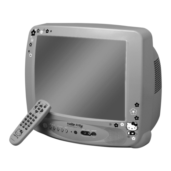
14" REMOTE CONTROL COLOR TELEVISION
WITH ON SCREEN DISPLAY
IMPORTANT SERVICE SAFETY INFORMATION .................. 1
BLOCK DIAGRAM ........................................................... 3
ALIGNMENT INSTRUCTIONS ........................................... 4
SERVICE MODE ADJUSTMENTS ................................ 4
ASSEMBLY ADJUSTMENTS ........................................ 5
PARENTAL CONTROL PASSWORD SETTINGS ............. 9
6KHz -3±3dB
VOLTAGE CHART .......................................................... 10
WAVEFORMS ................................................................. 13
SCHEMATIC DIAGRAM ................................................... 16
EXPLODED VIEW .......................................................... 17
ELECTRICAL PARTS LIST .............................................. 18
98-99 (A2-A1)
14-12 (A-1)
IC DESCRIPTION ........................................................... 25
23-36 (J-W)
TROUBLESHOOTING CHART .......................................... 32
37-65 (AA-FFF)
NO POWER ............................................................ 32
66-125 (GGG-125)
NO PICTURE .......................................................... 33
NO SOUND ............................................................ 34
CH DON'T STOP ..................................................... 35
NO COLOR ............................................................ 36
NO VERTICAL DEFLECTION .................................... 36
NO ON-SCREEN DISPLAY ....................................... 37
REMOTE CONTROL DOES NOT OPERATE ................ 37
MODEL
HKTV13
CONTENTS
#24-2001
EMERSON RADIO CORP.
Parsippany, NJ 07054
www.emersonradio.com
Table of Contents

Related Manuals for Emerson HKTV13


Summary of Contents for Emerson HKTV13
-
Page 1: Table Of Contents
DIMENSIONS ……………………… 376(W) x 341(H) x 376(D) mm REMOTE CONTROL DOES NOT OPERATE ……………. 37 SERVICE PUBLICATION #24-2001 Note. All the specifications and features are subject to change without notice. EMERSON RADIO CORP. ⓒ Copyright 2001, Emerson Radio Corp. All rights reserved. Parsippany, NJ 07054 www.emersonradio.com... -
Page 2: Important Service Safety Information
IMPORTANT SERVICE SAFETY INFORMATION - Guidelines for Color Television Receivers CAUTION : Do not attempt to modify this product in any way. Unau- GRAPHIC SYMBOLS : thorized modifications will not only void the warranty, but may lead to your being liable for any resulting property damage or user injury. The lightning flash with arrowhead symbol, Service work should be performed only after you are thoroughly within an equilateral triangle, is intended to alert... - Page 3 SUBJECT : IMPLOSION 4. Wall and shelf mounted installations using a commercial mounting kit, must follow the factory approved mounting instructions. A receiver mounted to a shelf or platform must retain its original 1. All direct viewed picture tubes are equipped with an integral implo- feet(or the equivalent thickness in spacers) to provide adequate sion protection system, but care should be taken to avoid damage air flow across the bottom, bolts or screws used for fasteners...
-
Page 4: Block Diagram
BLOCK DIAGRAM... -
Page 5: Alignment Instructions
ALIGNMENT INSTRUCTIONS 1. SERVICE MODE ADJUSTMENTS Follow the steps below whenever service adjustment is required. See Table- A and Table- B to determine if service adjustments are required. 1) How to enter the service mode using the user remote control. •... -
Page 6: Assembly Adjustments
ALIGNMENT INSTRUCTIONS Table-B DATA MODE ADJUSTMENT ITEMS REMARKS INITIAL RANGE Screen Adjustment Auto RF AGC Video Level (VIDEOL) 0 ~ 7 Must be set to 7 RF AGC Delay (RFAGCD) 0 ~ 63 Align RF AGC threshold FM Level (FM.LEV) 0 ~ 31 Must be set to 20 AGC Point... - Page 7 ALIGNMENT INSTRUCTIONS 2) FOCUS ADJUSTMENT • Turn in a local station and adjust the Focus Control knob (located on FBT) for best picture details at high light condition. 3) RF AGC DELAY ADJUSTMENT (S5) • Receive a good local channel. •...
- Page 8 ALIGNMENT INSTRUCTIONS 4-3. Vertical Size Adjustment • Select “ V.SIZE” item, adjust “ V.SIZE” data value to proper vertical size as follows. 5) WHITE BALANCE ADJUSTMENT(S8) • Receive a good local channel. • Enter the service mode and select service adjustment S8. •...
- Page 9 ALIGNMENT INSTRUCTIONS • Select Subbrightness item, adjust Subbrightness data value to obtain normal brightness level. • Press the DISPLAY button to memorize the data. CONTRAST • Fixed value = 27 TINT • Fixed value = 32 COLOR • Fixed value = 20 7) FACTORY OUTGOING MODE (S12 : FACT) •...
-
Page 10: Parental Control Password Settings
ALIGNMENT INSTRUCTIONS 3. PARENTAL CONTROL PASSWORD SETTINGS If the user forgets the password, set the Parental Control Password as follows. 1) CHANGE THE PASSWORD. • Turn the set on. • Direct the remote control to the Remote Sensor of the TV. •... -
Page 11: Voltage Chart
VOLTAGE CHART MODE MODE I101 2.37 2.73 1.94 2.63 2.36 2.22 0.49 2.44 2.88 4.25 0.51 2.88 4.25 0.51 3.56 4.92 0.57 3.04 0.65 2.25 1.98 0.32 2.29 0.28 2.39 4.89 3.11 4.85 4.84 MODE 3.94 I301 1.53 13.35 1.53 26.34 3.63 2.22... - Page 12 VOLTAGE CHART MODE MODE I701 4.89 I703 4.81 5.04 4.99 5.04 4.99 4.89 4.86 4.86 4.83 2.68 2.66 4.97 4.92 5.04 4.99 5.04 4.99 MODE 2.22 0.49 I801 6.72 4.12 4.89 163.8 173.53 4.95 4.89 14.4 11.02 3.37 4.53 3.21 2.69 2.47 2.35...
- Page 13 VOLTAGE CHART MODE MODE 5.10 5.03 4.67 5.02 Q201 Q702 3.36 3.32 2.52 2.48 1.25 0.13 38.67 37.58 5.09 5.01 Q401 Q703 0.63 0.31 0.01 1.25 0.54 0.01 5.00 4.95 Q403 Q704 5.03 4.98 0.01 0.68 4.40 4.34 9.50 0.02 5.10 5.03 Q404...
-
Page 14: Waveforms
WAVEFORMS (1) I101 PIN 19 (2) I101 PIN 20 (3) I101 PIN 21 (4) I101 PIN 23 (5) I101 PIN 40 (5) I101 PIN 44 (7) I101 PIN 46 (8) I301 PIN7... - Page 15 WAVEFORMS (9) I701 PIN 7 (10) I701 PIN 17 (12) I801 PIN 2 1) I701 PIN 18 (13) T402 PIN 25.5V (14) T402 PIN 10.5V (15) T402 PIN HEATER (16) T402 PIN 200V...
- Page 16 WAVEFORMS (17) T401 PIN H.V . (18) T801 PIN 133V (19) Q403 COLLECT OR (20) CR T SOCKET PIN B (21) CR T SOCKET PIN R (22) CR T SOCKET PIN G...
-
Page 17: Schematic Diagram
SCHEMATIC DIAGRAM... -
Page 18: Exploded View
SCREW CRT FIX 30X80 BK 4856013301 SCREW CRT FIX 30X140 YL PTRTPWH CRT AS NTSC 14" ITC CRT AS PTCPMSH CRT PCB ASS’Y HKTV13(DTQ-14V6NK) PTMPMSH MAIN PCB ASS’Y HKTV13(DTQ-14V6NK) 4857027101 HEAT SINK SPCC T1.0+SN 7174300811 SCREW TAPPTITE TT2 RND 3X8 MFZN... -
Page 19: Electrical Parts List
4859907910 CORD POWER AS ME301P+TER=1830 M351 4853535300 HOLDER BRKT FR HIPS BK Q402 TKSC5386-- KSC5386 ZZ202 PTSPPWH407 SPEAKER AS HKTV13(DTQ-14** common) R801 RX07B229JP R CEMENT 7W 2.2 OHM J BEN 15MM 4P PA601 4850703S50 CONNECTOR YH025-03+35098+ULW=200 R881 DEC7R0M140 POSISTOR ECPAC7R0M140... - Page 20 1/10 3.9K OHM J 2012 ZZ200 PTMPJ2H552 PCB CHIP MOUNT B AS RC226 HRFT101JCA R CHIP 1/10 100 OHM J 2012 HKTV13(DTQ-14V6NK) CC151 HCBK103KCA C CHIP CERA 50V X7R 0.01MF K 2012 RC228 HRFT103JCA R CHIP 1/10 10K OHM J 2012...
- Page 21 CEXF2C101V C ELECTRO 160V RSS 100MF (16X25) TP RC712 HRFT103JCA R CHIP 1/10 10K OHM J 2012 ZZ200 PTMPJBH552 PCB MAIN M-10 AS HKTV13(DTQ-14V6NK) RC713 HRFT103JCA R CHIP 1/10 10K OHM J 2012 2TM18006BE TAPE MASKING 6.2X500 RC731 HRFT103JCA R CHIP...
- Page 22 R M-OXIDE FILM 2W 0.82 OHM J SMALL C704 CEXF1H229V C ELECTRO 50V RSS 2.2MF (5X11) TP ZZ200 PTMPJRH552 PCB MAIN RADIAL AS HKTV13(DTQ-14V6NK) C705 CEXF1H109V C ELECTRO 50V RSS 1MF (5X11) TP C101 CEXF1H109V C ELECTRO 50V RSS 1MF (5X11) TP...
- Page 23 X502 5XEX3R579C CRYSTAL QUARTZ HC-49U 3.579545M (TP) J524 85801065GY WIRE COPPER AWG22 1/0.65 TIN COATING ZZ200 PTMPJAH552 PCB MAIN AXIAL AS HKTV13(DTQ-14V6NK) J525 85801065GY WIRE COPPER AWG22 1/0.65 TIN COATING 2TM14006LB TAPE MASKING 3M #232 6.0X2000M J533 85801065GY WIRE COPPER AWG22 1/0.65 TIN COATING...
- Page 24 R888 RC-2Z565KP R CARBON COMP 1/2 5.6M OHM K R401 RD-4Z472J- R CARBON FILM 1/4 4.7K OHM J ZZ300 PTCPMSH552 PCB CRT MANUAL AS HKTV13(DTQ-14V6NK) R405 RD-2Z751J- R CARBON FILM 1/2 750 OHM J I705 1AN5862K-- AN5862K R416 RD-2Z121J- R CARBON FILM...
- Page 25 1/10 470 OHM J 2012 CC724 HCBK103KCA C CHIP CERA 50V X7R 0.01MF K 2012 ZZ200 PTCPJ0H552 PCB CRT ODD SHAPE HKTV13(DTQ-14V6NK) CC725 HCQK330JCA C CHIP CERA 50V CH 33PF J 2012 C912 CH1BEE472M C CERA AC U/C/V 2.5KV 4700PF TP...
-
Page 26: Appendix
IC DESCRIPTION Appendix U-COM(I701) X’ TAL:32.768 KHz... - Page 27 IC DESCRIPTION Appendix 1. Abstract. This specification is 1-Tuner Mono Model for North/South America, CCD 1-Chip MICOM LC863228A. This MICOM supports the tuning and CCD system for NTSC only. 2. H/W Outline. 1) ROM : 28,672 x 8bits.tsc : 15,872 x 8 bits for CGROM. 2) RAM : 512 x 8bits.
- Page 28 IC DESCRIPTION Appendix 3) On Screen Displays function is interior designed. 4) Package. : 36 PIN SDIP. 5) Tuner (Pre-scaler.) C Bus. /PLL IC : TAU 6014-S(SIEMENS). 6) Remocon. : The IC of Transmission (MITSUBISHI M50560) C Bus) ◊ Apply one byte Read/Write mode. 7) E PROM.
- Page 29 IC DESCRIPTION Appendix - Auto Power On Function.(Power Restore function in the Special Menu) - Heat Run Function. --- OSD White Back-Ground - Sleep Timer. - Wake Up Time Function. - Off Time Function. - Remote Reception & Control. - Auto Tint.----------------------- (Option) - Power Restore.
- Page 30 IC DESCRIPTION Appendix 6. Pin Description Terminal Name Explanation Remarks P10/SDA0 ROM Data Main 6 bit input/output port IC Data Input/output can be specified for each bit ROM CLK Other function. P11/SCLK0 Main IC CLK IIC0 data I/O P12/SDA1 IIC0 clock output. Tuner Data IIC1 data I/O IIC1 clock output.
- Page 31 IC DESCRIPTION Appendix Terminal Name Explanation Blue output terminal of RGB image Fast blanking control signal Switch TV image Signal and caption / OSD image signal Output terminal Audio Mute Use only read data of LA76814/10 Use when does power off/on Power On Power off: Output Low(DC 0V) Power on: Output High(DC 5V)
- Page 32 IC DESCRIPTION Appendix I101 DCT814(LA76814) : IC VIDEO PROCESSOR AUDIO OUT SIF INPUT FM OUTPUT SIF APC FILTER PIF AGC SIF OUTPUT RF AGC OUT EXT. AUDIO INPUT PIF INPUT1 VCO FILTER PIF INPUT2 VCO COIL1 IF GND VCO COIL2 IF VCC APC FILTER FM FILTER...
-
Page 33: Troubleshooting Chart
TROUBLESHOOTING GUIDE Appendix 1. NO POWER... -
Page 34: No Picture
TROUBLESHOOTING GUIDE Appendix 2. NO PICTURE NG : GO to the figure c Check the waveform of I101 #46 OK : Go the figure d 1701 MICOM... -
Page 35: No Sound
TROUBLESHOOTING GUIDE Appendix 3. NO SOUND NG : Go to the figure e Check audio output signal of I101 #1 OK : Go to the figure f g 1701 MICOM... -
Page 36: Ch Don't Stop
TROUBLESHOOTING GUIDE Appendix 4. CH DON’ T STOP NG : Loss of signal or weak signal Check the input signal conditions OK : Go to the figure h... -
Page 37: No Color
TROUBLESHOOTING GUIDE Appendix 5. NO COLOR 6. NO VERTICAL DEFLECTION... -
Page 38: No On-Screen Display
TROUBLESHOOTING GUIDE Appendix 7. NO ON-SCREEN DISPLAY 8. REMOTE CONTROL DOES NOT OPERATE...