GE Corometrics 250cx Series Service Manual
Monitor
Hide thumbs
Also See for Corometrics 250cx Series:
- Service manual (252 pages) ,
- Operator's manual (250 pages)

Related Manuals for GE Corometrics 250cx Series


Summary of Contents for GE Corometrics 250cx Series
- Page 1 GE Healthcare Corometrics™ 250cx Series Monitor Service Manual Corometrics 250cx Series Monitor English 2036947-001 Revision J © 2013 General Electric Company. All Rights Reserved...
- Page 3 GE Healthcare Corometrics™ 250cx Series Monitor Service Manual Corometrics 250cx Series Monitor English 2036947-001 Revision J © 2013 General Electric Company. All Rights Reserved...
- Page 4 Warranty This product is sold by GE Healthcare with a GE repair warranty period of 12-month to cover labor and parts* (except for the expendable parts like fuses or batteries which have a 30-day warranty) under the terms and conditions set forth in the GE Healthcare Warranty Statement presented to the customer at the point of sale.
- Page 5 ПРЕДУПРЕЖДЕНИЕ Това упътване за работа е налично само на английски език. (BG) • Ако доставчикът на услугата на клиента изиска друг език, задължение на клиента е да осигури превод. • Не използвайте оборудването, преди да сте се консултирали и разбрали упътването за...
- Page 6 VÝSTRAHA Tento provozní návod existuje pouze v anglickém jazyce. (CS) • V případě, že externí služba zákazníkům potřebuje návod v jiném jazyce, je zajištění překladu do odpovídajícího jazyka úkolem zákazníka. • Nesnažte se o údržbu tohoto zařízení, aniž byste si přečetli tento provozní návod a pochopili jeho obsah.
- Page 7 Versuchen Sie nicht diese Anlage zu warten, ohne diese Serviceanleitung gelesen und verstanden zu haben. • Wird diese Warnung nicht beachtet, so kann es zu Verletzungen des Kundendiensttechnikers, des Bedieners oder des Patienten durch Stromschläge, mechanische oder sonstige Gefahren kommen. ΠΡΟΕΙΔΟΠΟΙΗΣΗ Το παρόν εγχειρίδιο σέρβις διατίθεται μόνο στα αγγλικά.
- Page 8 FIGYELMEZTETÉS Ezen karbantartási kézikönyv kizárólag angol nyelven érhető el. (HU) • Ha a vevő szolgáltatója angoltól eltérő nyelvre tart igényt, akkor a vevő felelőssége a fordítás elkészíttetése. • Ne próbálja elkezdeni használni a berendezést, amíg a karbantartási kézikönyvben leírtakat nem értelmezték.
- Page 9 BRĪDINĀJUMS Šī apkopes rokasgrāmata ir pieejama tikai angļu valodā. (LV) • Ja klienta apkopes sniedzējam nepieciešama informācija citā valodā, klienta pienākums ir nodrošināt tulkojumu. • Neveiciet aprīkojuma apkopi bez apkopes rokasgrāmatas izlasīšanas un saprašanas. • Šī brīdinājuma neievērošanas rezultātā var rasties elektriskās strāvas trieciena, mehānisku vai citu faktoru izraisītu traumu risks apkopes sniedzējam, operatoram vai pacientam.
- Page 10 ATENÇÃO Este manual de assistência técnica só se encontra disponível em inglês. (PT-PT) • Se qualquer outro serviço de assistência técnica solicitar este manual noutro idioma, é da responsabilidade do cliente fornecer os serviços de tradução. • Não tente reparar o equipamento sem ter consultado e compreendido este manual de assistência técnica.
- Page 11 ATENCION Este manual de servicio sólo existe en inglés. (ES) • Si el encargado de mantenimiento de un cliente necesita un idioma que no sea el inglés, el cliente deberá encargarse de la traducción del manual. • No se deberá dar servicio técnico al equipo, sin haber consultado y comprendido este manual de servicio.
-
Page 13: Table Of Contents
Table of Contents Compliance ..................................xviii Components of the Certified Systems ........................xviii Component Description ...............................xviii Exceptions ..................................xviii Monitor System EMC: Immunity Performance ....................xviii About this Manual ........................1 Scope and Intended Users .............................1 Conventions .................................... 1 User Responsibility ................................1 References ....................................2 Definitions of Terms ................................2 Symbols .................................... - Page 14 Table of Contents ® 1.5.4 DINAMAP Models PRO Series 100-400 and ProCare ............... 22 1.6 Theory of Operation ..............................23 1.6.1 Digital System Processor (DSP) / Display Board ................23 1.6.2 Main Board ..............................25 1.6.3 User-Interface Keypad & Volume/Alarm Keypad Boards ............26 1.6.4 Video Decoder Board ..........................
- Page 15 Table of Contents Chapter 4: Calibration ......................55 4.1 Calibration Schedule ..............................55 4.2 Environmental Requirements ..........................56 4.3 Tool Requirements ..............................56 4.4 Calibration Procedures ............................56 4.4.1 NIBP Calibration Check ..........................56 4.4.2 Recorder Photosensors Check ......................59 4.4.3 Recorder Calibration (offsets) Check ....................
- Page 16 Table of Contents 6.12 Dual Ultrasound Board Replacement ......................101 6.13 FECG/UA Board and MECG Board Replacement ..................102 6.14 SpO Carrier Board (with Nellcor/Masimo SpO Module) Replacement ........103 6.15 Isolated Power Supply Board Replacement .....................104 6.16 Front-end Motherboard Replacement ......................105 6.17 Recorder Assembly and Recorder Door Button Replacement ............107 6.18 Recorder Board Replacement .........................109 6.19 Recorder Stepper Motor Replacement .......................110 6.20 Recorder Paper-Out/Paper-Low Photosensor Replacement ............111...
- Page 17 Table of Contents E.1 Service Lock Screen ..............................154 E.2 Install Options Screens ............................155 E.3 Printing Setup Information ..........................159 E.4 Communications Setup Screen .........................159 E.5 Error Log Screen ...............................160 E.6 Diagnostic Control Screen ...........................161 E.7 J102 Screen ................................162 E.8 NIBP Calibration Screen ............................163 E.9 Setup Screen Defaults ............................163 E.9.1 Operator Setup Screens .........................164 E.9.2 Service Mode Screens ..........................167...
-
Page 18: Compliance
Compliance A GE brand Corometrics ™ 250cx Series Monitor bears CE mark CE-0459 indicating its conformity with the provisions of the Council Directive 93/42/EEC concerning medical devices and fulfills the essential requirements of Annex I of this directive. The device is manufactured in India; the CE mark is applied under the authority of Notified Body GMED (0459). -
Page 19: About This Manual
GE Healthcare Regional Service Center. This Product or any of its parts should not be repaired other than in accordance with written instructions provided by GE Healthcare and by GE Healthcare trained personnel. The Product must not be altered without GE Healthcare’s prior written approval. -
Page 20: References
WARNING: This device shall not be repaired other than in accordance with written instructions provided by GE Healthcare and by GE Healthcare trained personnel. CAUTION: Untied States federal law restricts this device to sale by or on the order of a licensed medical practitioner. -
Page 21: Symbols
About this Manual Term Definition Uterine Activity Ultrasound Symbols This section identifies the symbols that are displayed on the Corometrics 250cx Series monitor: Equipment Symbols TYPE BF EQUIPMENT: Type BF equipment is suitable for intentional external and internal application to the patient, excluding direct cardiac application. Type BF equipment has an F-type applied part. - Page 22 About this Manual Equipment Symbols practitioner. disposed as unsorted municipal waste and must be collected separately. Please contact the © 2013 by General Electric Company. All rights reserved. 2036947-001...
-
Page 23: Important Safety Information
The information contained in this service manual pertains only to those models of products which are marketed by GE Healthcare as of the effective date of this manual or the latest revision thereof. This service manual was prepared for exclusive use by GE Healthcare service personnel in light of their training and experience as well as the availability to them of parts, proper tools, and test equipment. -
Page 24: Warnings, Cautions And Notes
In addition, proper placement of the paddles in relation to the electrodes is required to minimize harm to the patient. WARNING: DEFIBRILLATION PROTECTION: When used with the GE-recommended accessories, the monitor is protected against the effects of defibrillator discharge. If monitoring is disrupted by the defibrillation, the monitor will recover. - Page 25 Important Saftey Information WARNING: EXPLOSION HAZARD: Do not use this equipment in the presence of flammable anesthetics or inside an oxygen tent. WARNING: GROUNDING: To avoid electrical shock hazard to the patient or the operator, do not defeat the three-wire grounding feature of the power cord by means of adaptors, plug modifications, or other methods.
- Page 26 CAUTION: ANNUAL SERVICING: For continued safety and performance of the monitor, verify the calibration, accuracy, and electrical safety of the monitor annually. Contact your GE service representative. © 2013 by General Electric Company. All rights reserved. 2036947-001...
-
Page 27: Electromagnetic Interference
Important Saftey Information CAUTION: DAILY TESTING: It is essential that the monitor and accessories be inspected every day. It is recommended practice to initiate the monitor’s selftest feature at the beginning of each monitoring session. CAUTION: ENVIRONMENT: The performance of the monitor has not been tested in certain areas, such as x-ray and imaging suites. - Page 28 Turn equipment in the vicinity off and on to isolate the offending equipment. • Reorient or relocate the other receiving device. • Increase the separation between the interfering equipment and this equipment. • If assistance is required, contact your GE service representative. © 2013 by General Electric Company. All rights reserved. 2036947-001...
-
Page 29: Chapter 1: System Description
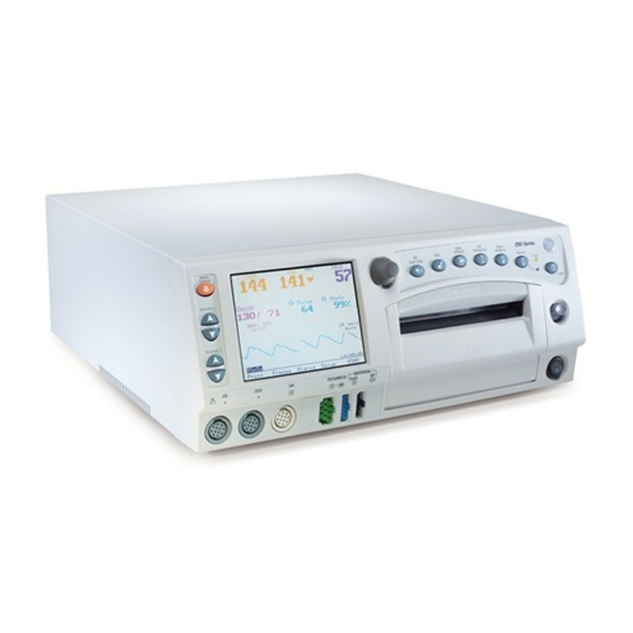
Chapter 1: System Description 1.1 System Overview The Corometrics 250cx Series monitor is a medical device for monitoring maternal/fetal parameters (Fetal Heart Rate, Uterine Activity, Maternal Non-Invasive Blood Pressure, Maternal Pulse Oximetry, and Maternal/ Fetal ECG) in labor and delivery (antepartum, intrapartum, and postpartum care). The monitor is equipped with an LCD display, which provides simultaneous display of fetal and maternal parameters plus the maternal waveforms, and a recorder, which prints continuous trends and alphanumeric data on one strip chart. - Page 30 Chapter 1: System Description Each monitor unit has its unique 13-Digit product serial number which contains embedded information about the unit manufacturing date and site (See Figure 1-1). Product Code Description 259CX-A (Nellcor, India Build) 259CX-B (Nellcor, US Build) 259CX-C (Masimo, India Build) 259CX-D (Masimo, US Build) 259CX-X (India Build) Figure 1-1 Global Serial Number Format (13-Digit)
-
Page 31: Front Panel Controls, Indicators, And Connectors
Chapter 1: System Description 1.2 Front Panel Controls, Indicators, and Connectors Figure 1-2 Front Panel View A. Display: The monitor display is divided into several sections. The content and layout of the display can change, depending on which functions are installed in the monitor and the modes of operation in use. B. - Page 32 Chapter 1: System Description F. UA Reference Button: This button sets a baseline for uterine activity pressure monitoring. G. Paper Advance Button: Pressing this button advances the strip chart paper at a rate of 40 cm/min for as long as the button is held down. H.
-
Page 33: Display Description
Chapter 1: System Description U. Volume Button (FHR2 Decrease): This button is used to decrease the fetal heart rate (FHR2) sound volume of the second ultrasound channel (US2). Volume settings have no effect on the processing used to determine heart rate. The Volume buttons work in conjunction with the volume control settings on the US/US2 Setup screen and on the FECG Setup screen. -
Page 34: Primary Labor Parameters
Chapter 1: System Description The monitor LCD display is designed to show the information listed below: 1.3.1 Primary Labor Parameters These parameters, shown on the upper portion of the screen (See Figure 1-3), include Fetal Heart Rate 1 (FHR1), Fetal Heart Rate 2 (FHR2), and Uterine Activity (UA). Each parameter can have several modes depending on the type of its input. - Page 35 Chapter 1: System Description Description of softkeys: Figure 1-4 Display Softkeys A. Mode Title Softkeys: Selects US, US2, FECG, NIBP, MHR/P, or MSpO Setup screens. B. ECG Scale Softkey: Selects 0.25x, 0.5x, 1x, 2x, 4x, or Auto. C. MECG Lead Softkey: Selects Lead I, II, or III. D.
- Page 36 Chapter 1: System Description Figure 1-5 Maternal Vital Signs History Screen Softkeys A. Print Softkey: Prints one page (screen) of the table. B. PrintAll Softkey: Prints all pages (screens). C. View Softkey: Scrolls through the data Counterclockwise for newest data or Clockwise for oldest data D.
-
Page 37: Rear Panel Descriptions
Chapter 1: System Description 1.4 Rear Panel Descriptions CAUTION: The maximum nondestructive voltage that may be applied to the rear panel connectors is 0 volts. Do not connect cables to these connectors without ensuring the connectors comply with leakage- current requirements of one of the following applicable standards: UL 60601-1, CSA C22.2 No. 601.1 or IEC/EN 60601-1. - Page 38 This connector is often referred to as the Analog Interface Connector. F. External VGA Connector (J112): This 15-pin sub-D connector is for interfacing to an external VGA display. Use of GE-recommended external display will allow monitor front panel display video to be replicated remotely.
-
Page 39: Peripherals Description
Chapter 1: System Description are output at +60 dB with a bandwidth of 0.5 to 40 Hz. The output level from this port is 10 V/mV for FECG and 1 V/mV for MECG. J. Fetal Acoustic Stimulator Connector: Connector for Corometrics 146 Fetal Acoustic Stimulator (FAST). -
Page 40: Quantitative Sentinel/Perinatal System
Chapter 1: System Description A “telemetry disconnected” symbol ( ) will be printed on the strip chart paper if the telemetry receiver is unplugged from the monitor, or the telemetry system (transmitter or receiver) is turned off, or the telemetry receiver does not detect any active mode information from its corresponding transmitter. -
Page 41: Theory Of Operation
Chapter 1: System Description 1.6 Theory of Operation The Corometrics 250cx Series system is made up of front-end and back-end sections, system power supply, and recorder module. The Main board forms the heart of the monitor control functions. The Main board along with the communications board forms the back-end section of the monitor. - Page 42 Chapter 1: System Description Figure 1-8 System Block Diagram © 2013 by General Electric Company. All rights reserved. 2036947-001...
-
Page 43: Main Board
Chapter 1: System Description 1.6.2 Main Board The Main board makes up the central processing unit for the monitor unit. The Main board accepts simultaneously processed parameters directly from four separate modules. The minimum configuration monitor has only the DSP board as an input module. Heart rate (ultrasound and or FECG), uterine activity data, mode information, and FMD data flow from the DSP board to the Main board via DSP board FPGA shared memory. -
Page 44: User-Interface Keypad & Volume/Alarm Keypad Boards
Chapter 1: System Description 1.6.3 User-Interface Keypad & Volume/Alarm Keypad Boards The user-interface keypad board is responsible for two functions, a) input controls, and b) the recorder chart light feature. The board contains most of the front panel buttons (except for the volume and alarm cancel buttons) and receives input from the Trim Knob Control. -
Page 45: Mspo Carrier Board
Chapter 1: System Description All the signals entering this board are patient isolated and signals leaving this board though the MSpO cable are also isolated. 1.6.8 MSpO Carrier Board The SpO carrier board holds the SpO module. It receives MSpO patient cable connections from the universal front-end connector board and internal cable on its isolated side and routes them to the connected NELL3-S, Nellcor MP-506 or NELL-3, or Masimo MS-11 or MS-2011 modules. -
Page 46: Isolated Power Supply Board
Chapter 1: System Description sent through the frontend motherboard to the DSP where they are digitized and processed. No isolation is present from the patient connector through the ultrasound board as the plastic ultrasound transducer forms the physical isolation barrier. 1.6.12 Isolated Power Supply Board The isolated power supply board provides all of the isolated power for the FECG/UA board, MECG board and the carrier board which in turn feeds the two SpO... -
Page 47: Chapter 2: Installation
2.4 Installation Procedure 2.4.1 Strip Chart Recorder Paper Load CAUTION: Use GE-approved recorder paper only. Using the wrong paper may damage the recorder print head and product inferior print quality. CAUTION: The monitor recorder shall be loaded with the paper at all times. This reduces particle build-up on the print head and facilitates opening the recorder door. - Page 48 Chapter 2: Installation To load strip chart recorder paper perform below steps: 1. Press down the latch on the right side of the strip chart recorder door (See Figure 2-1). 2. Fan the pack of Z-fold paper on all sides to loosen any folds and to ensure proper feed of the paper through the recorder.
-
Page 49: Peripheral Connections
Chapter 2: Installation 2.4.2 Peripheral Connections If present, connect the below optional peripherals to the Corometrics 250cx series monitor as per the following instructions: Remote Event Marker: Plug the marker connector into its corresponding jack on the rear side of the monitor. Corometric 340 Telemetry / Mini Telemetry system: Plug the interconnect cable (Part number: 1563AAO) into the Telemetry Connector (J101) on the rear side of the unit (Refer to Corometric 340 Telemetry / Mini Telemetry service manuals for installation details). - Page 50 Chapter 2: Installation 2. Use the Trim Knob Control to select the Setup softkey to display the General Setup screen and set the correct date and time (“Figure 2-7”). Set the paper speed in accordance with the hospital or local requirements.
- Page 51 Chapter 2: Installation 10. Use the Trim Knob Control to select Restart softkey to accept the settings and reboot the unit. 11. Perform the checkout procedures as instructed in chapter 3 before putting the monitor into use. Figure 2-7 Figure 2-8 Figure 2-9 Figure 2-10 Figure 2-11...
- Page 52 Chapter 2: Installation © 2013 by General Electric Company. All rights reserved. 2036947-001...
-
Page 53: Chapter 3: Maintenance And Checkout
Chapter 3: Maintenance and Checkout This chapter includes planned maintenance procedures as well as checkout procedures required after Corometrics 250cx series product installation, repair, or maintenance. These procedures must be performed by authorized service personnel. 3.1 Procedures Schedule Table 3-1 lists all planned maintenance and checkout procedures, specifies when and how often each procedure should be performed, and provides the approximate time taken to perform each procedure. -
Page 54: Environmental Requirements
Chapter 3: Maintenance and Checkout 3.1.1 Environmental Requirements The system shall be installed, serviced, and operated within the environmental conditions described in section A.1. 3.2 Tool Requirements The following table lists the service tools required to perform the planned maintenance and checkout procedures: Table 3-2: Tool Requirements for Planned Maintenance and Checkout Procedures Procedure Name... -
Page 55: Cleaning (Thermal Print Head)
This section provides instructions to confirm the operational and functional performance of the transducers. 3.3.3.1 Ultrasound Transducer Checks NOTE: Always use GE-approved transducers only. 1. Visually inspect the transducer case, the cable, the strain relief, and the connector pins for any signs of damage. -
Page 56: Functional Checks
Ultrasound audio is generated from the speaker on the rear side of the monitor. 3.3.3.2 TOCO Transducer Checks NOTE: Always use GE-approved transducers only. 1. Visually inspect the transducer case (especially on the diaphragm located on the bottom of the transducer), the cable, the strain relief, and the connector pins for any signs of damage. - Page 57 Incorrect paper speed setting results in inaccurate waveform prints on the strip chart paper. 3.3.4.2 Self-Test Routine 1. Make sure GE-approved strip chart paper is loaded into the unit recorder. 2. Turn the unit power on. 3. Depress the Test Button and confirm the following: a.
- Page 58 Chapter 3: Maintenance and Checkout b. Lamp Test: The yellow Record Indicator illuminates. c. Recorder Test: The recorder prints the message TEST: ARE ALL DOTS PRINTED? followed by two vertical lines and four horizontal lines. The two vertical lines should appear continuous and indicate a fully functional print head.
- Page 59 1. Make sure the monitor unit and the PS320 simulator are both turned off. 2. Connect a Y adapter cable (GE Part number: 1442AAO) to the monitor and then connect the 3-Lead MECG cable (orderable through GE part number: 2025177-055) to the MECG connector of the Y adapter and the...
- Page 60 Chapter 3: Maintenance and Checkout b. The ALARM SILENCE X:XX message box appears on the screen and a countdown is started. 14. Wait for the user-specified re-alarm time to end and confirm that the audio alarm is once again generated from the rear panel speaker.
- Page 61 Chapter 3: Maintenance and Checkout 3.3.4.5 MSpO Check 1. Use the Trim Knob Control on the monitor front panel to select MSpO on the General screen to access the Setup screen and configure as follows: MSpO a. For Nellcor Models: Set Response Time to Fast, Print Interval to 2 minutes, and % O Trace to On.
- Page 62 1. Make sure the monitor unit and the PS320 simulator are both turned off. 2. Connect a Y adapter cable (GE Part number: 1442AAO) to the monitor and then connect the 3-Lead MECG cable (orderable through GE part number: 2025177-055) to the MECG connector of the Y adapter and the...
- Page 63 1. Make sure the monitor unit and the PS320 simulator are both turned off. 2. Connect a Y adapter cable (GE Part number: 1442AAO) to the monitor and then connect the 3-Lead FECG cable (orderable through GE part number: 2025177-055) to the FECG connector of the Y adapter and the...
- Page 64 Corometrics 325 simulator use instructions. 1. Make sure the monitor and the PS320 simulator are both turned off. 2. Connect a GE-approved ultrasound transducer to the US input connector of the monitor and connect the ® Fluke mechanical fetal heart (MFH-1) to the US1 port of the PS320 simulator.
- Page 65 Chapter 3: Maintenance and Checkout 9. Decrease the US value from 120 BPM baseline to 90 BPM in the PS320 simulator. Confirm the following on the monitor display and the recorder: a. The FHR1 value immediately shows 90 ± 1. b.
- Page 66 Chapter 3: Maintenance and Checkout 4. Use the Trim Knob Control of the monitor to go to Service Mode and access the Install Options Screen 2 and set Pressure units to mmHg. 5. Take a note of the Default TOCO Reference value. NOTE: The monitor is shipped from the factory with the Default TOCO Reference value set at 10 mmHg (1.3 kPa).
-
Page 67: Pattern Memory Check
1. Make sure the monitor and the PS320 simulator are both turned off. ® 2. Connect the FECG and TOCO cables (orderable through GE part number: 2025177-055 and Fluke Part number: 2462519) to the corresponding connectors of the monitor and the PS320 simulator (See Appendix 3. - Page 68 1. Make sure the monitor and the PS320 simulators are both turned off. 2. Connect a Y adapter cable (GE Part number: 1442AAO) to the monitor and then connect the 3-Lead FECG cable (orderable through GE part number: 2025177-055) to the FECG connector of the Y adapter and the...
- Page 69 Chapter 3: Maintenance and Checkout d. The FHR2 heartbeat indicator ( ) flashes at a rate of 150 times per minute. ♥ e. The FHR2 mode shows US. The recorder prints the messages FECG and US on the center margin of the strip chart paper. g.
-
Page 70: Nibp Calibration Check
Chapter 3: Maintenance and Checkout b. The FHR1 heartbeat indicator ( ) responds to the input. ♥ c. The recorder prints the heart rate tracing corresponding to the rate and the trace is plain black. 7. Hold the ultrasound transducer connected to US2 input in your hand with the transducer front facing the palm of your hand and use your other hand to gently press and depress the back of the transducer rhythmically while maintaining a steady rate. - Page 71 Chapter 3: Maintenance and Checkout 3. Turn on the safety analyzer and set it to measure the ground resistance. 4. Measure the resistance between the ground (earth) terminal of the Power Inlet Module and the Equipotential Lug on the rear side of the monitor unit. The resistances shall be 100mΩ or less. 3.3.7.3 Ground (Earth) Leakage Current and Enclosure Leakage Current Checks Perform this check on the monitor unit only, with no other equipment (peripherals) attached.
- Page 72 Chapter 3: Maintenance and Checkout 6. Turn on the monitor unit. 7. In normal conditions and in all possible operating modes, the patient leakage currents shall be 10 μA or less. 8. If required by local ordinances, in single-fault conditions and in all possible operating modes, the patient (source/sink) leakage currents shall be 50 μA or less.
-
Page 73: Chapter 4: Calibration
Chapter 4: Calibration This chapter includes calibration procedures required for Corometrics 250cx series monitor repair, or maintenance. These procedures must be performed by authorized service personnel. Each Corometrics 250cx Series monitor is calibrated in the factory prior to shipment to the customer and so no calibration is required upon the installation of the monitor unit. -
Page 74: Environmental Requirements
Chapter 4: Calibration 4.2 Environmental Requirements The system shall be installed, serviced, and operated within the environmental conditions described in section A.1. 4.3 Tool Requirements The following table lists the service tools required to perform the calibration procedures: Table 4-2: Tool Requirements for Calibration Procedures Procedure Name Service Tools Needed (QTY) Adult Cuff (1), 3”... - Page 75 Chapter 4: Calibration 1. Wrap an adult cuff around a 3” rigid cylinder. 2. Connect a standard 12-foot NIBP hose between the cuff and the monitor. 3. If hand inflation is needed, connect a hand pump bulb between the cuff and the NIBP hose. 4.
- Page 76 Chapter 4: Calibration NOTE: To stop Calibration Verification select Done, which appears after the Verify softkey has been pressed. The monitor will vent pressure to atmosphere and re-zero the transducers. 4.4.1.2 Transducer Calibration 1. Use the Trim Knob Control to set Mode to Calibrate in the NIBP Calibration screen. The monitor will inflate the cuff to approximately 200 mmHg.
-
Page 77: Recorder Photosensors Check
4.4.2.1 Paper-Low Photosensor Adjustment 1. Remove the top cover of the monitor as instructed in section 6.1. 2. Load the recorder with GE-approved strip chart paper. Make sure that there are no black squares showing. 3. Turn on the monitor unit. - Page 78 4.4.2.2 Paper-Out Photosensor Adjustment 1. Remove the top cover of the monitor as instructed in section 6.1. 2. Load the recorder with GE-approved strip chart paper. Make sure that there are no black squares showing. 3. Turn on the monitor unit.
-
Page 79: Recorder Calibration (Offsets) Check
4.4.3 Recorder Calibration (offsets) Check 1. Load the monitor recorder with GE-approved strip chart paper. 2. Turn the monitor on. 3. Use the Trim Knob Control to access the Diagnostic Control screen and set the Recorder Calibration into On and press the Trim Knob Control to select it. - Page 80 Chapter 4: Calibration © 2013 by General Electric Company. All rights reserved. 2036947-001...
-
Page 81: Chapter 5: Diagnostics And Troubleshooting
Chapter 5: Diagnostics and Troubleshooting This chapter lists some of the major symptoms of Corometrics 250cx Series monitors as well as the possible causes and solutions. For any necessary part replacements or adjustments, follow the instructions provided in See Chapter 6. Always read all the warnings, cautions, notes, and other information provided in the “Important Safety Information”... - Page 82 Inadequate ultrasound Apply adequate gel is used. ultrasound gel. Make sure GE-approved The recorder is off or out paper is installed in the of paper. recorder. Press the Record button. Perform the recorder...
- Page 83 General Troubleshooting Table Symptom Description Possible Causes Actions and Solutions Paper supply in recorder Install a new pack of is low or paper incorrectly GE-approved paper in the loaded. recorder. Perform the recorder Paper-low photosensor is photosensors check out of calibration.
- Page 84 Chapter 5: Diagnostics and Troubleshooting General Troubleshooting Table Symptom Description Possible Causes Actions and Solutions SW1 switch #7 is Disable SW1 switch #7. incorrectly set. Restart the monitor and check the CPU software When the monitor is turned on, SYSTEM version of the monitor.
-
Page 85: Ultrasound Troubleshooting Table
Chapter 5: Diagnostics and Troubleshooting 5.2 Ultrasound Troubleshooting Table Ultrasound Troubleshooting Table Symptom Description Possible Causes Actions and Solutions Confirm that the Ultrasound transducer is transducer is securely not properly connected connected to the monitor to the monitor unit. unit. Reposition the transducer Ultrasound transducer is and wait for a few... - Page 86 Chapter 5: Diagnostics and Troubleshooting Ultrasound Troubleshooting Table Symptom Description Possible Causes Actions and Solutions Use GE-approved Inappropriate ultrasound ultrasound transducers. transducer used. Do not use refurbished transducers. Keep sheets and gown off Environmental noise transducer. Do not hold transducer with hand.
-
Page 87: Fecg Troubleshooting Table
Chapter 5: Diagnostics and Troubleshooting 5.3 FECG Troubleshooting Table FECG Troubleshooting Table Symptom Description Possible Causes Actions and Solutions FECG cable is not Confirm that the cable properly connected to the is securely connected to monitor unit. the monitor unit. Attachment pad or leg Confirm the pad or the plate is not securely... -
Page 88: External Uterine Activity Troubleshooting Table
Chapter 5: Diagnostics and Troubleshooting 5.4 External Uterine Activity Troubleshooting Table External Uterine Activity Troubleshooting Table Symptom Description Possible Causes Actions and Solutions Confirm that the TOCO transducer is not transducer is securely properly connected to the connected to the monitor monitor unit. - Page 89 Chapter 5: Diagnostics and Troubleshooting External Uterine Activity Troubleshooting Table Symptom Description Possible Causes Actions and Solutions Make sure to wait ten seconds following UA Reference button is powering on the monitor pressed before the UA and/or connecting the circuitry is stabilized. transducer to the UA connector.
-
Page 90: Internal Uterine Activity Troubleshooting Table
Chapter 5: Diagnostics and Troubleshooting 5.5 Internal Uterine Activity Troubleshooting Table Internal Uterine Activity Troubleshooting Table Symptom Description Possible Causes Actions and Solutions Confirm that the The transducer is not transducer is securely properly connected to the connected to the monitor monitor unit. -
Page 91: Mecg Troubleshooting Table
Chapter 5: Diagnostics and Troubleshooting 5.6 MECG Troubleshooting Table MECG Troubleshooting Table Symptom Description Possible Causes Actions and Solutions The cable is not properly Confirm that the cable connected to the monitor is securely connected to unit. the monitor unit. Check electrodes and re- Electrode gel is dried. - Page 92 Chapter 5: Diagnostics and Troubleshooting Blood Pressure Troubleshooting Table Symptom Description Possible Causes Actions and Solutions Reposition the cuff and Improper cuff position or confirm that the cuff is loose cuff. properly tightened. Restrict patient limb Maternal movement movement. Restrain limb if necessary.
-
Page 93: Maternal Pulse Oximetry Troubleshooting Table
Chapter 5: Diagnostics and Troubleshooting Blood Pressure Troubleshooting Table Symptom Description Possible Causes Actions and Solutions Monitor is unable to WEAK SIGNAL message is shown on the determine the blood S7.8 Assess patient situation. display. pressure due to insufficient signal. 5.8 Maternal Pulse Oximetry Troubleshooting Table Maternal Pulse Oximetry Troubleshooting Table Symptom Description... -
Page 94: Main Board Troubleshooting - Voltage Checks
Chapter 5: Diagnostics and Troubleshooting Maternal Pulse Oximetry Troubleshooting Table Symptom Description Possible Causes Actions and Solutions Verify the settings of SW1 switch on the main board are correct. If the REPAIR message is shown in MSpO area of the System error or self-test symptom still exists, the S8.4... -
Page 95: Fecg/Ua Board Troubleshooting - Voltage Adjustments
Chapter 5: Diagnostics and Troubleshooting 5.10 FECG/UA Board Troubleshooting – Voltage Adjustments SENSITIVE TO ELECTROSTATIC DISCHARGE This procedure includes ESD sensitive parts. ESD control guidelines must be followed during this procedure to ensure that static charges are safely conducted to the ground and not through the sensitive device, to prevent damage to the equipment. - Page 96 Chapter 5: Diagnostics and Troubleshooting 4. Use a hex key to adjust the one hex-head screw (See Figure 5-2) on the right side of the recorder assembly (the one lower hex-head screw on the side where stepper motor is attached) 5.
-
Page 97: Horizontal Offset Adjustment
Chapter 5: Diagnostics and Troubleshooting 5.11.2 Horizontal Offset Adjustment SENSITIVE TO ELECTROSTATIC DISCHARGE This procedure includes ESD sensitive parts. ESD control guidelines must be followed during this procedure to ensure that static charges are safely conducted to the ground and not through the sensitive device, to prevent damage to the equipment. -
Page 98: Light Printing
(Figure 5-5) and the table to fix the issue. Load the monitor recorder with the GE-approved chart paper. Close the recorder door and allow 1-2 pages to roll out by pressing the Paper Advance button. Set the display to service mode and then press test button to get a test print. - Page 99 Chapter 5: Diagnostics and Troubleshooting Figure 5-5 Recorder Light Printing Symptom - Troubleshooting Flowchart © 2013 by General Electric Company. All rights reserved. 2036947-001...
- Page 100 Chapter 5: Diagnostics and Troubleshooting Recorder Light Printing Troubleshooting Table Symptom Description Possible Causes Actions and Solutions Use GE-Recommended fetal chart paper only Inappropriate fetal chart (Part numbers: 2009828-CAO, 2009828-DAO, paper is used. 2009828-FAO). Use cotton swabs and methanol or isopropyl alcohol to clean the thermal print head (See section 3.3.2).
- Page 101 Chapter 5: Diagnostics and Troubleshooting Recorder Light Printing Troubleshooting Table Symptom Description Possible Causes Actions and Solutions Note: Don’t touch the TPH heating element with Thermal print head (TPH) bare hand. is not aligned properly Perform Horizontal Offset Adjustment: with respect to the roller. Press and hold the 1) Loosen four Socket Head Lock screws (label recorder door toward...
- Page 102 Chapter 5: Diagnostics and Troubleshooting Recorder Light Printing Troubleshooting Table Symptom Description Possible Causes Actions and Solutions horizontal lines is 0.490 ±0. 010 from the inside edge of the right hand edge of the paper. Use film scale or vernier calipers for measurement. 3) Check the print line alignment is within spec.
-
Page 103: Chapter 6: Repair And Replacement Procedures
CAUTION: Genuine spare parts manufactured or sold by GE Healthcare must only be used for all repair and replacement procedures. NOTE: Standard service tools (such as nut driver, long nose pliers, hex keys, and Phillips screw driver) are required to perform the repair and replacement procedures. -
Page 104: Top Cover, Top Cover Gasket, And Timekeeping Ram Chip Replacement
Chapter 6: Repair and Replacement Procedures 6.1 Top Cover, Top Cover Gasket, and Timekeeping RAM Chip Replacement SENSITIVE TO ELECTROSTATIC DISCHARGE This procedure includes ESD sensitive parts. ESD control guidelines must be followed during this procedure to ensure that static charges are safely conducted to the ground and not through the sensitive device, to prevent damage to the equipment. -
Page 105: Speaker Replacement
Chapter 6: Repair and Replacement Procedures 6.2 Speaker Replacement SENSITIVE TO ELECTROSTATIC DISCHARGE This procedure includes ESD sensitive parts. ESD control guidelines must be followed during this procedure to ensure that static charges are safely conducted to the ground and not through the sensitive device, to prevent damage to the equipment. -
Page 106: Dsp/Display Board Replacement
Chapter 6: Repair and Replacement Procedures 6.3 DSP/Display Board Replacement SENSITIVE TO ELECTROSTATIC DISCHARGE This procedure includes ESD sensitive parts. ESD control guidelines must be followed during this procedure to ensure that static charges are safely conducted to the ground and not through the sensitive device, to prevent damage to the equipment. -
Page 107: Communication Board Replacement
Chapter 6: Repair and Replacement Procedures 4. Disconnect the DSP-to-Keypad ribbon cable from the J5 connector on the DSP/Display board (See Figure 6-5). 5. Disconnect the external display cable from J9 connector on the DSP/Display board (See Figure 6-1). 6. Use a Phillips screw driver to remove the two screws that attach the DSP/Display board to the chassis (See Figure 6-6). -
Page 108: Pneumatics Assembly Replacement
Chapter 6: Repair and Replacement Procedures 6.5 Pneumatics Assembly Replacement SENSITIVE TO ELECTROSTATIC DISCHARGE This procedure includes ESD sensitive parts. ESD control guidelines must be followed during this procedure to ensure that static charges are safely conducted to the ground and not through the sensitive device, to prevent damage to the equipment. - Page 109 Chapter 6: Repair and Replacement Procedures 4. Tilt the front bezel forward and away from the chassis to make the rear side of the NIBP connector on the bezel accessible (See Figure 6-9). 5. Pull and disconnect the two red pneumatics tubes from the NIBP connector on the back of the bezel (See Figure 6-10).
-
Page 110: Main Board Replacement
Chapter 6: Repair and Replacement Procedures 6.6 Main Board Replacement SENSITIVE TO ELECTROSTATIC DISCHARGE This procedure includes ESD sensitive parts. ESD control guidelines must be followed during this procedure to ensure that static charges are safely conducted to the ground and not through the sensitive device, to prevent damage to the equipment. -
Page 111: Display Assembly Replacement
Chapter 6: Repair and Replacement Procedures 5. Pull up the pneumatics board gently to disconnect it from the main board and remove it. 6. Disconnect the power supply cable from the J8 connector on the main board (See Figure 6-14). 7. - Page 112 Chapter 6: Repair and Replacement Procedures 9. Disconnect the Keypad-to-Volume ribbon cable from its connector on volume keypad board (See Figure 6-17). 10. Use a Phillips screw driver to remove the screw that attach display mounting bracket to the front bezel (See Figure 6-18) and then remove the screw that attach the bracket to the display assembly (See Figure 6-19) to remove the bracket.
-
Page 113: Power Switch Assembly Replacement
Chapter 6: Repair and Replacement Procedures 6.8 Power Switch Assembly Replacement SENSITIVE TO ELECTROSTATIC DISCHARGE This procedure includes ESD sensitive parts. ESD control guidelines must be followed during this procedure to ensure that static charges are safely conducted to the ground and not through the sensitive device, to prevent damage to the equipment. -
Page 114: Trim Knob Control Assembly Replacement
Chapter 6: Repair and Replacement Procedures 6.9 Trim Knob Control Assembly Replacement SENSITIVE TO ELECTROSTATIC DISCHARGE This procedure includes ESD sensitive parts. ESD control guidelines must be followed during this procedure to ensure that static charges are safely conducted to the ground and not through the sensitive device, to prevent damage to the equipment. -
Page 115: Keypads Replacement
Chapter 6: Repair and Replacement Procedures 10. Pull out the trim knob and use long nose pliers to remove the encoder washer and the encoder. 11. Reverse steps to re-install. 6.10 Keypads Replacement SENSITIVE TO ELECTROSTATIC DISCHARGE This procedure includes ESD sensitive parts. ESD control guidelines must be followed during this procedure to ensure that static charges are safely conducted to the ground and not through the sensitive device, to prevent damage to the equipment. - Page 116 Chapter 6: Repair and Replacement Procedures b. Disconnect the encoder cable from the keypad board (See Figure 6-23). c. Use a Phillips screw driver to remove the two screws that attach the keypad bracket to the front bezel (See Figure 6-24) and remove the keypad bracket. d.
-
Page 117: Main Power Supply / Fan Replacement
Chapter 6: Repair and Replacement Procedures 6.11 Main Power Supply / Fan Replacement SENSITIVE TO ELECTROSTATIC DISCHARGE This procedure includes ESD sensitive parts. ESD control guidelines must be followed during this procedure to ensure that static charges are safely conducted to the ground and not through the sensitive device, to prevent damage to the equipment. - Page 118 Chapter 6: Repair and Replacement Procedures Figure 6-25 Figure 6-26 Figure 6-27 Figure 6-28 © 2013 by General Electric Company. All rights reserved. 2036947-001...
-
Page 119: Dual Ultrasound Board Replacement
Chapter 6: Repair and Replacement Procedures 6.12 Dual Ultrasound Board Replacement SENSITIVE TO ELECTROSTATIC DISCHARGE This procedure includes ESD sensitive parts. ESD control guidelines must be followed during this procedure to ensure that static charges are safely conducted to the ground and not through the sensitive device, to prevent damage to the equipment. -
Page 120: Fecg/Ua Board And Mecg Board Replacement
Chapter 6: Repair and Replacement Procedures 6.13 FECG/UA Board and MECG Board Replacement SENSITIVE TO ELECTROSTATIC DISCHARGE This procedure includes ESD sensitive parts. ESD control guidelines must be followed during this procedure to ensure that static charges are safely conducted to the ground and not through the sensitive device, to prevent damage to the equipment. - Page 121 Chapter 6: Repair and Replacement Procedures 6.14 SpO Carrier Board (with Nellcor/Masimo SpO Module) Replacement SENSITIVE TO ELECTROSTATIC DISCHARGE This procedure includes ESD sensitive parts. ESD control guidelines must be followed during this procedure to ensure that static charges are safely conducted to the ground and not through the sensitive device, to prevent damage to the equipment.
-
Page 122: Isolated Power Supply Board Replacement
Chapter 6: Repair and Replacement Procedures 6. Pull up the SpO carrier board with Nellcor/Masimo MSpO module assembly to release it from the front- end motherboard (See Figure 6-34). 7. Reverse steps to re-install. NOTE: If the existing SpO carrier board is replaced with a different SpO board (e.g. -
Page 123: Front-End Motherboard Replacement
Chapter 6: Repair and Replacement Procedures 6.16 Front-end Motherboard Replacement SENSITIVE TO ELECTROSTATIC DISCHARGE This procedure includes ESD sensitive parts. ESD control guidelines must be followed during this procedure to ensure that static charges are safely conducted to the ground and not through the sensitive device, to prevent damage to the equipment. - Page 124 Chapter 6: Repair and Replacement Procedures Figure 6-37 Figure 6-38 Figure 6-39 Figure 6-40 Figure 6-41 © 2013 by General Electric Company. All rights reserved. 2036947-001...
-
Page 125: Recorder Assembly And Recorder Door Button Replacement
Chapter 6: Repair and Replacement Procedures 6.17 Recorder Assembly and Recorder Door Button Replacement SENSITIVE TO ELECTROSTATIC DISCHARGE This procedure includes ESD sensitive parts. ESD control guidelines must be followed during this procedure to ensure that static charges are safely conducted to the ground and not through the sensitive device, to prevent damage to the equipment. - Page 126 Chapter 6: Repair and Replacement Procedures 15. Reverse steps to re-install. NOTE: When re-installing the recorder assembly mounting bracket, do not tighten the four screws until the front bezel is installed. Make sure that the two front bezel fiducial pins are aligned with the recorder slots and the three tabs on the bottom of front bezel are placed into their corresponding slots on the chassis (See Figure 6-45) before tightening the screws.
-
Page 127: Recorder Board Replacement
Chapter 6: Repair and Replacement Procedures 6.18 Recorder Board Replacement SENSITIVE TO ELECTROSTATIC DISCHARGE This procedure includes ESD sensitive parts. ESD control guidelines must be followed during this procedure to ensure that static charges are safely conducted to the ground and not through the sensitive device, to prevent damage to the equipment. -
Page 128: Recorder Stepper Motor Replacement
Chapter 6: Repair and Replacement Procedures 7. Disconnect the paper-low sensor cable from J5 connector on the recorder board (See Figure 6-48). Make a note of the orientation of the connector for proper re-installation. 8. Disconnect recorder paper-loading sensor cable from the J8 connector on the recorder board. 9. -
Page 129: Recorder Paper-Out/Paper-Low Photosensor Replacement
Chapter 6: Repair and Replacement Procedures 4. Slide the stepper motor out to remove it. 5. Reverse steps to re-install. 6.20 Recorder Paper-Out/Paper-Low Photosensor Replacement SENSITIVE TO ELECTROSTATIC DISCHARGE This procedure includes ESD sensitive parts. ESD control guidelines must be followed during this procedure to ensure that static charges are safely conducted to the ground and not through the sensitive device, to prevent damage to the equipment. - Page 130 Chapter 6: Repair and Replacement Procedures NOTE: When re-installing the sensor housings on to the recorder assembly using the two socket-head screws, make sure that the top of the sensor housing is aligned with the top of the print head bracket (See Figure 6-54) before tightening the screws.
-
Page 131: Recorder Paper-Loading Photosensor Replacement
Chapter 6: Repair and Replacement Procedures 6.21 Recorder Paper-Loading Photosensor Replacement SENSITIVE TO ELECTROSTATIC DISCHARGE This procedure includes ESD sensitive parts. ESD control guidelines must be followed during this procedure to ensure that static charges are safely conducted to the ground and not through the sensitive device, to prevent damage to the equipment. -
Page 132: Recorder Thermal Print Head Replacement
Chapter 6: Repair and Replacement Procedures 6.22 Recorder Thermal Print Head Replacement SENSITIVE TO ELECTROSTATIC DISCHARGE This procedure includes ESD sensitive parts. ESD control guidelines must be followed during this procedure to ensure that static charges are safely conducted to the ground and not through the sensitive device, to prevent damage to the equipment. -
Page 133: Front Bezel Replacement
Chapter 6: Repair and Replacement Procedures 8. Follow below steps to re-install a new thermal print head: a. Carefully remove the new print head from the packaging. DO NOT TOUCH any of the contact pins. b. Record the voltage rating marked on the decal affixed to the bottom of the print head. This value is the new VHEAD voltage. - Page 134 Chapter 6: Repair and Replacement Procedures 3. Disconnect the DSP-to-LCD Decoder ribbon cable from J2 connector on the DSP/Display board (See Figure 6-4). 4. Disconnect the DSP-to-Keypad ribbon cable from J5 connector on the DSP/Display board (See Figure 6-5). 5. Use a Phillips screw driver to remove the two screws (on both sides of the monitor) that attach the front bezel to the chassis (See Figure 6-8).
-
Page 135: Chapter 7: Service Parts
Chapter 7: Service Parts This chapter illustrates the Corometrics 250cx Series monitor service parts and includes the orderable service kit part numbers. A complete Field Replaceable Unit (FRU) list is also provided. © 2013 by General Electric Company. All rights reserved. 2036947-001... -
Page 136: Illustrated Parts
Chapter 7: Service Parts 7.1 Illustrated Parts Figure 7-1 Exploded View © 2013 by General Electric Company. All rights reserved. 2036947-001... - Page 137 Chapter 7: Service Parts Orderable Callout Part Description Orderable Service Kit Description Service Kit Number Top cover 2025177-030 Top cover FRU Top cover gasket 2025177-031 Top cover gasket FRU Communication board with plate 2025177-070 Communication board with plate FRU Speaker 2025177-003 Speaker FRU DSP board...
- Page 138 Chapter 7: Service Parts Figure 7-2 Card Cage Boards Orderable Callout Part Description Orderable Service Kit Description Service Kit Number Isolated power supply board 2025177-066 Isolated power supply board FRU FECG/UA board 2025177-065 FECG/UA board FRU MECG board 2025177-075 MECG board FRU 2025177-010 carrier board with Nellcor oximetry FRU carrier board with...
- Page 139 Chapter 7: Service Parts Figure 7-3 Recorder Orderable Callout Part Description Orderable Service Kit Description Service Kit Number Recorder thermal print head 2025177-056 Recorder thermal print head FRU Recorder stepper motor 2025177-057 Recorder stepper motor FRU Recorder paper-low photosensor Recorder paper-out 2025177-058 Recorder photosensors FRU photosensor...
- Page 140 Chapter 7: Service Parts Figure 7-4 Labels Orderable Callout Part Description Orderable Service Kit Description Service Kit Number Connectors label Main keypad label Volume pad label Masimo/Nellcor overlay label See section 7.2 Labels FRU Kit (Language-specific) Paper loading label Rear panel label Electrical shock hazard label VGA connector label Serial number label...
-
Page 141: Labels
Chapter 7: Service Parts 7.2 Labels This section includes the list of product labels. For the location of each label, refer to Figure 7-3. NOTE: The following labels shown are for illustration purposes only. The content on the labels shown here may be slightly different from the content of the actual labels on the system. -
Page 142: Power Cords
Chapter 7: Service Parts Orderable Orderable Label Image Label Name Service Kit Service Kit Number Description Rear panel label Electrical shock hazard label VGA connector label Serial number label Non-Orderable Not applicable NOTE: Use below part numbers to order the language-specific label FRU kits: 2025177-034 : Label FRU Kit, English (US) 2025177-059 : Label FRU Kit, Lang 4 (Czech, Greek, Indonesian, Lithuanian, Portuguese, Turkish) 2025177-060 : Label FRU Kit, Lang 3 (Danish, Dutch, French, German, Japanese, Spanish) -
Page 143: Fru List
Chapter 7: Service Parts 7.4 FRU List Part Number Part Description 2025177-002 Hardware FRU Kit BRACKET , GROUNDING PLATE BRACKET , PRINTER SUPPORT, 120 V4 BRACKET 120 SERIES V4 BRACKET MTG 120 SERIES V4 BUSHING INSULATOR SNAP CABLE,TIE MOUNT,3/4IN,ADH,.BACK CLIP EMI 4 PRONGS GROUND WIRE ASSEMBLY JACKSOCKET,4-40,.312LG, NUT, M3.5 HEX, STL ZN, DIN 934... - Page 144 Chapter 7: Service Parts Part Number Part Description 2025177-003 Speaker FRU Kit Speaker assembly (Wire and connector included) 2025177-006 Fan FRU Kit Fan assembly (connector included) 2025177-064 Dual Ultrasound Board FRU Kit Dual ultrasound board 2025177-065 FECG/UA Board FRU Kit FECG/UA board 2025177-066 Isolated Power Supply Board FRU Kit...
- Page 145 Chapter 7: Service Parts Part Number Part Description 2025177-082 Front Bezel with Cables FRU Kit Front bezel assembly (Ultrasound, ECG, UA, SpO cable assemblies and sockets plus NBP socket and display lens included) 2025177-073 Keypad/Volume Pad FRU Kit Main user interface PCB assembly Keyboard pad, side Keyboard pad, main 2025177-026...
- Page 146 Chapter 7: Service Parts Part Number Part Description Rear panel label Electrical shock hazard label VGA connector label Coro259 Masimo overlay label Coro259 Nellcor overlay label 2025177-078 Main Board FRU Kit Main board assembly 2025177-042 Print Head Cable FRU Kit Recorder thermal print head Recorder print head cable assembly 2025177-043...
- Page 147 Chapter 7: Service Parts Part Number Part Description 2025177-056 Recorder Thermal Print Head FRU Kit Thermal print head M3 x 5 Phillips Screw 2025177-057 Recorder Stepper Motor FRU Kit Stepper motor assembly 4-40 Phillips Screw 2025177-058 Recorder Photosensors FRU Kit Paper-low photosensor assembly Paper-out photosensor assembly Paper-load photosensor assembly...
- Page 148 Chapter 7: Service Parts © 2013 by General Electric Company. All rights reserved. 2036947-001...
-
Page 149: Appendix A: Technical Specifications
Appendix A: Technical Specifications This section contains the list of the technical specifications for the Corometrics 250cx Series monitors. NOTE: Specifications are subject to change without notice. © 2013 by General Electric Company. All rights reserved. 2036947-001... -
Page 150: General Product Specifications
Appendix A: Technical Specifications A.1 General Product Specifications General Product Specifications Category Specifications Power Requirements Nominal Line Voltage: 100VAC 120 VAC 220 VAC 230 VAC 240 VAC Line Frequency: 50/60 Hz 50/60 Hz 50/60 Hz 50/60 Hz 50/60 Hz Power Consumption (maximum): 100 W 100 W 0.4 A... -
Page 151: Strip Chart Recorder Specifications
Appendix A: Technical Specifications A.2 Strip Chart Recorder Specifications Strip Chart Recorder Specifications Category Specifications Heart Rate Scale Domestic International Chart Width: 7 cm 8 cm Scaling: 30 bpm/cm 20 bpm/cm Range: 30–240 bpm 50–210 bpm Resolution: 1 bpm 1 bpm Uterine Activity Scale Tocotransducer Chart Width:... -
Page 152: Operating Modes Specifications
Appendix A: Technical Specifications A.3 Operating Modes Specifications CAUTION: The monitor may produce incorrect results if operated outside the specified parameter specifications in below table. Operating Modes Specifications Category Specifications FECG Mode Technique: Peak detecting, beat-to-beat cardiotachometer Heart Rate Counting Range: 30–240 bpm Heart Rate Resolution: ±... - Page 153 Appendix A: Technical Specifications Operating Modes Specifications Category Specifications Uterine Activity Mode Tocotransducer Range (typical): 0–100 mmHg (0–13.3 kPa) Resolution: 1 mmHg (0.13 kPa) Bandwidth: dc to 0.5 Hz Excitation Voltage: < 0.1 mmHg/°C (0.013 kPa/°C), excluding transducer Zero Set Temperature Drift: <...
- Page 154 Appendix A: Technical Specifications Operating Modes Specifications Category Specifications Pacemaker Detection/Rejection: Input Voltage Range: ± 2.5 mV to ± 700mV Input Pulse Width: 0.1 to 2 ms Pulse Rise/Fall Time: < 10% of pulse width; not greater than 100 μs Overshoot/Undershoot: 2 mV CAUTION:...
- Page 155 The 250cx Series blood pressure parameter complies with Compliance the American National Standard for Electronic or Automated Sphygmomanometers [AAMI/ANSI SP10-1992]. The GE monitor values are based on the oscillometric method of noninvasive blood pressure measurement and correspond to comparisons with intra-aortic values within ANSI/AAMI Standards for accuracy.
- Page 156 Appendix A: Technical Specifications Operating Modes Specifications Category Specifications Maternal Pulse Oximetry Mode (Masimo) Technique: Spectrophotometry and plethysmography. Sensor Accuracy LNOP ® DC-I, LNOP-Adt, LNCS PC-I, and LNCS-Adt Sensor Model > 30 kg Weight Range ± 2% Saturation No Motion ±...
- Page 157 Appendix A: Technical Specifications Operating Modes Specifications Category Specifications Interfering Substances Carboxyhemoglobin may erroneously increase readings. The level of increase is approximately equal to the amount of carboxyhemoglobin present. Dyes, or any substance containing dyes, that change usual arterial pigmentation may cause erroneous readings 1) Accuracy specified when used with Masimo SET pulse oximetry modules using PC or LNC series patient cables.
- Page 158 Appendix A: Technical Specifications Operating Modes Specifications (Continued) Category Specifications Maternal Pulse Oximetry Mode (Nellcor) Technique: Spectrophotometry and plethysmography. Range: Sensor Type and Accuracy 70%–100%: ® OxiMax Sensor Models ± 2 digits MAX-A ± 3 digits DS-100A Saturation Range: 1–100% Pulse Rate Range: 30–250 bpm Accuracy:...
-
Page 159: Appendix B: Alarm Summary
Appendix B: Alarm Summary Type Condition Visible Advisory Audible Advisory An alarm setting (audio or high/low displays to the left of the limit) is turned off. FHR mode title. Alarm Defaults Audio: on Volume: 5 Limits: High = 160 bpm, Low = 120 FHR limit (high or low) actively being FHR numeric flashes. - Page 160 Appendix B: Alarm Summary Type Condition Visible Advisory Audible Advisory Alarm Defaults — Audio: on Volume: 5 Limits: High = 120 bpm, Low = 50 Re-alarm: 120 sec MHR/P limit (high or low) actively MHR/P numeric flashes. being violated. MHR/P The tachycardia response time is <...
-
Page 161: Appendix C: Electromagnetic Compatibility
Appendix C: Electromagnetic Compatibility Changes or modifications to this system not expressly approved by GE Healthcare can cause EMC issues with this or other equipment. This system is designed and tested to comply with applicable regulation regarding EMC and must be installed and put into service according to the EMC information stated in this appendix. -
Page 162: Manufacturer's Guidance And Declaration - Electromagnetic Immunity
Appendix C: Electromagnetic Compatibility C.2 Manufacturer’s Guidance and Declaration – Electromagnetic Immunity The Corometrics 250cx Series Maternal/Fetal Monitor is intended for use in the electromagnetic environment specified below. It is the responsibility of the customer or user to enssure that the monitor unit is used in such an environment. - Page 163 Appendix C: Electromagnetic Compatibility Electromagnetic Environment - Immunity Test EN6061 Test Level Compliance Level Guidance Portable and mobile RF communications equipment should not be used closer to any part of the equipment, including cables, than the recommended separation distance calculated from the equation applicable to the frequency of the transmitter.
-
Page 164: Recommended Separation Distances
The use of accessories, transducers and cables other than those specified may result in increased emissions or decreased immunity performance of the equipment or system. The table below lists cables, transducers, and other applicable accessories with which GE Healthcare claims EMC compliance. - Page 165 Appendix C: Electromagnetic Compatibility Part No Description Maximum Lengths ECG Cables 1442AAO Y Adapter Cable Maternal/Fetal ECG, Rectangular .46 m /18 in 1442BAO FECG Socket Adapter .46 m /18 in 1553AAO Multi-Link Cable, 3 Lead ECG Maternal, AHA, Rectangle 3.6 m / 12 ft 1553BAO Multi-Link Cable, 3 Lead ECG Maternal, IEC, Rectangle 3.6 m /12 ft...
- Page 166 Appendix C: Electromagnetic Compatibility Part No Description Maximum Lengths 1567AAO 120/Traceview Cable, HP Mon to Traceview 120 3 m / 10 ft 1568AAO 120/Traceview Adapter Cable .36m / 1 ft 1569AAO 120/Peritronics Cable, Cent Surv Intfc Cbl 120 3 m / 10 ft 1580AAO Cable Assy, 120 to WATCHCHILD 3 m / 10 ft...
-
Page 167: Appendix D: Ps320 Fetal Simulator Setup
1. Parts to be ordered from Fluke Biomedical: • One PS320 Fetal Monitoring Kit for GE Corometrics (Fluke part number: 2794057): This kit includes the following items: - One PS320 fetal simulator unit - One MFH-1 Mechanical Heart Probe and Fetal Heart Cable... -
Page 168: Ps320 Fetal Simulator Setup
Appendix D: PS320 Fetal Simulator Setup D.2 PS320 Fetal Simulator Setup This section provides instructions to perform the PS320 fetal simulator setup. NOTE: The PS320 fetal simulator needs periodic calibration. Always use a calibrated PS320 unit for performing tests. 1. Connect the ECG/US/TOCO simulation cables to their corresponding connectors on PS320 fetal simulator and Corometrics 250cx Series monitor unit as illustrated in Figure D-1. - Page 169 Appendix D: PS320 Fetal Simulator Setup Figure D-1 PS320 Setup NOTE: For FECG connection, use Fetal, Fet/Mat, and Reference connectors on the PS320 simulator. For MECG connection, use Fet/Mat, Maternal, and Reference connectors on the PS320 simulator. 2. Turn on the monitor unit and the PS320 fetal simulator. 3.
- Page 170 Appendix D: PS320 Fetal Simulator Setup © 2013 by General Electric Company. All rights reserved. 2036947-001...
-
Page 171: Appendix E: Service Mode Screens
Appendix E: Service Mode Screens The Corometrics 250cx Series monitor provides a variety of options that are selected in the setup screens on the display using the Trim Knob Control. Depending on the intended user, the setup screens can generally be categorized into two groups: a. -
Page 172: Service Lock Screen
Appendix E: Service Mode Screens E.1 Service Lock Screen The Service Lock screen (See Figure E-1) is the first screen when entering the monitor service mode. Figure E-1 Service Lock Screen To access this screen: 1. Select the Setup softkey in the General screen to display the General Setup screen. 2. -
Page 173: Install Options Screens
Appendix E: Service Mode Screens E.2 Install Options Screens Upon entering the correct access code in Service Lock screen and pressing the Trim Knob Control, the monitor displays Install Options Screen 1 (See Figure E-2). This screen includes the following option fields to configure: Figure E-2 Install Options Screen 1 •... - Page 174 Appendix E: Service Mode Screens • VS Print Interval: This field provides two options for the printing of blood pressure and MSpO values on the strip chart paper: Real-Time: Values are printed according to the actual clock time (9:33, 9:48, 10:03, etc.). о...
- Page 175 Appendix E: Service Mode Screens • Scale: This field is only available on Corometrics 259cx model. Two below scale options can be selected for printing the MSpO trends. The scale is printed on the paper along with the trend. Auto: The trend plots on an expanded scale of 60–100% or 50–100%, depending on the paper*. о...
- Page 176 Appendix E: Service Mode Screens from the previously calculated heart rate is not printed on the strip chart paper. When Off is selected, all heart rate values are printed on the strip chart paper without regard to previous rates. When FECG artifact elimination is turned on, the monitor does not print any new FHR value which differs by more than ±25 BPM from the previously calculated heart rate value.
-
Page 177: Printing Setup Information
Appendix E: Service Mode Screens Factory: Select this option to make all monitor settings revert back to the factory default settings о (See section E.9.2) on the next power-on or restart. Hospital: Select this option to let the monitor utilizes the hospital-preferred settings (not the factory о... -
Page 178: Error Log Screen
Appendix E: Service Mode Screens Select the COMM softkey on Install Options Screen 1 screen to access the Communications Setup screen and set below fields: Baud rate: This field sets the baud rate for communication with an external device. Use the Trim Knob •... -
Page 179: Diagnostic Control Screen
Appendix E: Service Mode Screens 2. Use the Page softkey to display the next screen (page), if applicable. The last page wraps back to the first page. 3. Use the Print softkey to print the displayed screen (page) on the strip chart recorder. 4. -
Page 180: J102 Screen
Appendix E: Service Mode Screens • Run Time: This field displays the amount of time the monitor has been turned on since the last time that this field was cleared. The time is displayed in hours, minutes, and seconds. To clear this field (reset the timer), activate the Clear softkey to the right of the run time field. -
Page 181: Nibp Calibration Screen
Appendix E: Service Mode Screens Figure E-7 J102 Test Screen The Range and Voltage fields can be displayed using a decimal point or a comma as a separator. Each activation of the Decimal softkey at the bottom of the screen alternates between using a decimal and a comma. -
Page 182: Operator Setup Screens
Appendix E: Service Mode Screens E.9.1 Operator Setup Screens Hospital- Operator Setup Factory Default Option Field Name Field Options Preferred Screen (set in the factory) Option FHR Volume 200-140, Off High FECG or FHR Alarm Limits 60-140, Off 160bpm 120bpm US/US2 Audio Alarms On, Off... - Page 183 Appendix E: Service Mode Screens Hospital- Operator Setup Factory Default Option Field Name Field Options Preferred Screen (set in the factory) Option Auto, MECG, MSpO Source Auto NIBP MHR/P Trace On, Off Volume MHR/P High High Alarms 100-250 35-120 50 bpm Alarm Volume MECG Lead I, II, III...
- Page 184 Appendix E: Service Mode Screens Hospital- Operator Setup Factory Default Option Field Name Field Options Preferred Screen (set in the factory) Option Off, Happy Birthday, Brahms’ Lullaby, Play Song Rock-a-Bye-Baby, Song Volume Brightness 0-9 (nine = brightest) United States: 3 cm/min Paper Speed 1-3 cm/min International: 1 cm/min...
-
Page 185: Service Mode Screens
Appendix E: Service Mode Screens E.9.2 Service Mode Screens Hospital- Service Setup Factory Default Option Field Name Field Options Preferred Screen (set in the factory) Option Set according to Set according to Language shipping destination shipping destination United States: 60 Hz Line Frequency 50 Hz, 60 Hz International: 50 Hz... - Page 186 Appendix E: Service Mode Screens Hospital- Service Setup Factory Default Option Field Name Field Options Preferred Screen (set in the factory) Option Fetal Alert/Alarm Off, Alarms, Alerts Alert Suspend On, Off 120 - 300 seconds Re-Alarm in 5-second 120 seconds (MECG and SpO only) intervals...
-
Page 187: Appendix F: Cpu Software Upgrade
Appendix F: CPU Software Upgrade This section provides instructions to upgrade the CPU software of the Corometrics 250 series monitors. F.1 Tool Requirement • Windows ® Computer or Laptop • Software Installation CD-ROM • Serial Port Flasher Cable (Part number: 1203AAO) for computers/laptops with a serial port OR USB flasher cable (Part number: 2024454-001) for computers/laptops with a USB port F.2 Upgrade Procedure 1. - Page 188 Appendix F: CPU Software Upgrade 8. Insert the software installation CD-ROM into the CD-ROM drive of the computer or laptop. 9. Locate flasher.exe file on the CD-ROM and run it. 10. Answer Yes to the first warning dialog box. 11. Look at the “Intended” column of data. Ensure that these options are appropriate for your monitor. NOTE: All of the options except Fetal Movement and Spectra Alerts can be modified.
-
Page 189: Appendix G: Corometrics Tm 325 Simulator Setup And Use
Appendix G: Corometrics 325 Simulator Setup and GE Healthcare has discontinued the sales of The Corometrics 325 fetal simulator and recommends an ® alternate fetal simulator, i.e. PS320 simulator manufactured by Fluke Biomedical, as a substitute for Corometrics 325 fetal simulator to perform the tests and troubleshooting on the Corometrics 250cx Series monitors. - Page 190 Appendix G: Corometrics 325 Simulator Setup and Use 2. Connect the 325 simulator’s ECG cable to the MECG input of the adapter. 3. Use the Trim Knob Control to access the MHR/P Setup screen. 4. Set the MHR/P source to MECG. 5.
- Page 191 Appendix G: Corometrics 325 Simulator Setup and Use • The alarm tone is silenced. • The ALARM SILENCE X:XX message box appears on the screen and a countdown is started. 17. Wait the user-specified re-alarm time and verify that the alarm tone is once again emitted from the rear panel speaker.
-
Page 192: Mecg Input Check
Appendix G: Corometrics 325 Simulator Setup and Use G.3 MECG Input Check 1. Connect the simulator’s ECG cable to the MECG connector on the monitor adapter cable (Part number: 1442AAO). 2. Connect the simulator’s UA cable to the UA connector on the monitor. 3. -
Page 193: Fecg Input Check
Appendix G: Corometrics 325 Simulator Setup and Use • The ECG “beep” volume is generated from the rear panel speaker. The volume can be adjusted on the MHR/P Setup screen. • Set HR/PR Trace to On in the MHR/P Setup screen The recorder should print a continuous line at 60 bpm on the top grid of the strip chart paper. - Page 194 Appendix G: Corometrics 325 Simulator Setup and Use • The ECG “beep” volume of the rear panel speaker can be increased or decreased using the left pair of Volume buttons (Set the volume to the desired level). • The recorder prints a continuous line at 120 bpm on the HR grid of the strip chart paper. 8.
-
Page 195: Ultrasound Input Check
Appendix G: Corometrics 325 Simulator Setup and Use 19. Set the simulator’s ECG Rate switch to the MANUAL position and the Manual Adjustment knob to the counterclockwise position. Disconnect the ECG simulator cable from the Y adapter cable. Verify the following on the monitor: •... -
Page 196: Uterine Activity Check
Appendix G: Corometrics 325 Simulator Setup and Use • The FHR1 value immediately reflects this new input rate. • The strip chart recorder prints at the last input rate for an additional 3 seconds before blanking the heart rate data and printing a continuous line at the new input rate. 7. -
Page 197: Pattern Memory Check
Appendix G: Corometrics 325 Simulator Setup and Use • The UA value is the default setting. • The UA mode is TOCO. • The recorder prints a continuous line at the default value on the uterine activity channel of the strip chart paper. -
Page 198: Dual Heart Rate Check (Non-Pattern, Fecg/Us Modes)
Appendix G: Corometrics 325 Simulator Setup and Use NOTE: US/US2 cannot be tested simultaneously unless two 325 simulators or two ultrasound transducers are used. Do not perform the dual ultrasound test using one 325 simulator and one ultrasound transducer or a conflict between enable lines will occur. NOTE: FECG/MECG cannot be tested simultaneously unless two 325 simulators are used. -
Page 199: Dual Heart Rate Check (Non-Pattern, Dual Us Modes)
Appendix G: Corometrics 325 Simulator Setup and Use Section Switch Name Setting Mode Ultrasound/FMD Level Rate RAMP GENERAL Pattern Memory 5. If not already on, depress the Record button. 6. Verify the following on the monitor: • The FHR1 value reads 120 bpm ± 1 bpm. •... -
Page 200: Fetal Movement Detection Check
Appendix G: Corometrics 325 Simulator Setup and Use 4. Use your finger to rub the face of the ultrasound transducer connected to the US2 input connector and maintain a steady rate and verify the following on the monitor: • The FHR2 value responds to the rubbing. •... - Page 202 Shanghai, People’s Republic of China 201203 Fax: + 1 414 355 3790 Tel: + 86 21 5257 4650 Fax: + 86 21 5208 2008 GE Medical Systems Information Technologies, a General Electric Company, going to market as GE Healthcare www.gehealthcare.com...