Table of Contents
This service information is designed for experienced repair technicians only and is not designed for use by the general public.
It does not contain warnings or cautions to advise non-technical individuals of potential dangers in attempting to service a product.
Products powered by electricity should be serviced or repaired only by experienced professional technicians. Any attempt to
service or repair the products dealt with in this service information by anyone else could result in serious injury or death.
There are special components used in this equipment which are important for safety. These parts are marked by
Diagrams, Circuit Board Diagrams, Exploded Views and Replacement Parts List. It is essential that these critical parts should be replaced
with manufacturer's specified parts to prevent shock, fire or other hazards. Do not modify the original design without permission of
manufacturer.
In order to avoid frostbite, be assured of no refrigerant leakage during the installation or repairing of refrigerant circuit.
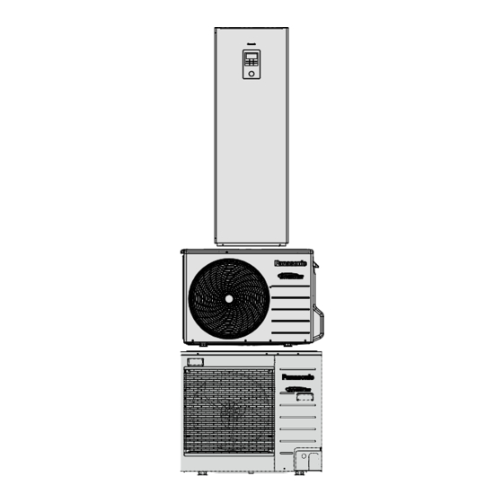
Air-to-Water Hydromodule + Tank
Indoor Unit
WH-ADC0309H3E5
WARNING
IMPORTANT SAFETY NOTICE
PRECAUTION OF LOW TEMPERATURE
Order No: PAPAMY1607068CE
Outdoor Unit
WH-UD03HE5-1
WH-UD05HE5-1
WH-UD07HE5-1
WH-UD09HE5-1
Destination
Europe
Turkey
in the Schematic
!
© Panasonic Corporation 2016.
Table of Contents

Related Manuals for Panasonic WH-ADC0309H3E


Summary of Contents for Panasonic WH-ADC0309H3E
- Page 1 Do not modify the original design without permission of manufacturer. PRECAUTION OF LOW TEMPERATURE In order to avoid frostbite, be assured of no refrigerant leakage during the installation or repairing of refrigerant circuit. © Panasonic Corporation 2016.
-
Page 2: Table Of Contents
TABLE OF CONTENTS 1. Safety Precautions ..........4 12.17 Anti Freeze Control ........114 12.18 Solar Operation (Optional) ......115 2. Specifications ............. 6 12.19 Boiler Bivalent Control ......116 12.20 External Room Thermostat Control WH-ADC0309H3E5 WH-UD03HE5-1 ..6 (Optional) ..........118 WH-ADC0309H3E5 WH-UD05HE5-1 .. - Page 3 18.4 To Remove RCCB ........200 18.5 To Remove Electronic Controller ....200 18.6 To Remove Flow Switch and Air Purge Valve ............201 18.7 To Remove Water Pump ......201 18.8 To Remove Bottle Complete ..... 202 18.9 To Remove Water Filter ......202 19.
-
Page 4: Safety Precautions
1. Safety Precautions Read the following “SAFETY PRECAUTIONS” carefully before installation of Air-To-Water Hydromodule + Tank (here after referred to as “Tank Unit”). Electrical works and water installation works must be done by licensed electrician and licensed water system installer respectively. - Page 5 WARNING 19. During pump down operation, stop the compressor before remove the refrigeration piping. Removal of refrigerant piping while compressor is operating and valves are opened will cause suck-in of air, abnormal high pressure in refrigerant cycle and result in explosion, injury etc. 20.
-
Page 6: Specifications
2. Specifications WH-ADC0309H3E5 WH-UD03HE5-1 Item Unit Outdoor Unit Performance Test Condition EN 14511 Condition A35W7 (Ambient/Water) 3.20 Cooling Capacity BTU/h 10900 kcal/h 2750 3.08 Cooling EER kcal/hW 2.64 Condition A7W35 A2W35 (Ambient/Water) 3.20 3.20 Heating Capacity BTU/h 10900 10900 kcal/h 2750 2750 5.00... - Page 7 Item Unit Outdoor Unit ø Single Power Source (Phase, Voltage, Cycle) Condition A35W7 A7W35 A2W35 (Ambient/Water) Input Power Cooling: 1.04 Heating: 0.64 Heating: 0.90 Maximum Input Power For Heatpump System 2.59 Power Supply 1 : Phase (Ø) / Max. Current (A) / Max. Input Power (W) 1Ø...
- Page 8 Item Unit Indoor Unit Volume Expansion Vessel Capacity of Integrated Electric Heater / OLP TEMP kW / °C 3.00 / 80 Tank Volume (Spec / Nett) 200 / 185 Max. Tank Water Set Temperature °C Tank Coil Surface Heat / Cool Maximum Working Pressure Tank Circuit...
-
Page 9: Wh-Adc0309H3E5 Wh-Ud05He5-1
WH-ADC0309H3E5 WH-UD05HE5-1 Item Unit Outdoor Unit Performance Test Condition EN 14511 Condition A35W7 (Ambient/Water) 4.50 Cooling Capacity BTU/h 15300 kcal/h 3870 2.69 Cooling EER kcal/hW 2.32 Condition A7W35 A2W35 (Ambient/Water) 5.00 4.20 Heating Capacity BTU/h 17100 14300 kcal/h 4300 3610 4.63 3.11 Heating COP... - Page 10 Item Unit Outdoor Unit ø Single Power Source (Phase, Voltage, Cycle) Condition A35W7 A7W35 A2W35 (Ambient/Water) Input Power Cooling: 1.67 Heating: 1.08 Heating: 1.35 Maximum Input Power For Heatpump System 2.59 Power Supply 1 : Phase (Ø) / Max. Current (A) / Max. Input Power (W) 1Ø...
- Page 11 Item Unit Indoor Unit Protection Device Residual Current Circuit Breaker (30) Volume Expansion Vessel Capacity of Integrated Electric Heater / OLP TEMP kW / °C 3.00 / 80 Tank Volume (Spec / Nett) 200 / 185 Max. Tank Water Set Temperature °C Tank Coil Surface Heat / Cool...
-
Page 12: Wh-Adc0309H3E5 Wh-Ud07He5-1
WH-ADC0309H3E5 WH-UD07HE5-1 Item Unit Outdoor Unit Performance Test Condition EN 14511 Condition A35W7 (Ambient/Water) 6.00 Cooling Capacity BTU/h 20500 kcal/h 5160 2.63 Cooling EER kcal/hW 2.26 Condition A7W35 A2W35 (Ambient/Water) 7.00 6.55 Heating Capacity BTU/h 23900 22300 kcal/h 6020 5630 4.46 3.34 Heating COP... - Page 13 Item Unit Outdoor Unit ø Single Power Source (Phase, Voltage, Cycle) Condition A35W7 A7W35 A2W35 (Ambient/Water) Input Power Cooling: 2.28 Heating: 1.57 Heating: 1.96 Maximum Input Power For Heatpump System 4.59 Power Supply 1 : Phase (Ø) / Max. Current (A) / Max. Input Power (W) 1Ø...
- Page 14 Item Unit Indoor Unit Protection Device Residual Current Circuit Breaker (30) Volume Expansion Vessel Capacity of Integrated Electric Heater / OLP TEMP kW / °C 3.00 / 80 Tank Volume (Spec / Nett) 200 / 185 Max. Tank Water Set Temperature °C Tank Coil Surface Heat / Cool...
-
Page 15: Wh-Adc0309H3E5 Wh-Ud09He5-1
WH-ADC0309H3E5 WH-UD09HE5-1 Item Unit Outdoor Unit Performance Test Condition EN 14511 Condition A35W7 (Ambient/Water) 7.00 Cooling Capacity BTU/h 23900 kcal/h 6020 2.43 Cooling EER kcal/hW 2.09 Condition A7W35 A2W35 (Ambient/Water) 9.00 6.70 Heating Capacity BTU/h 30700 22800 kcal/h 7740 5760 4.13 3.13 Heating COP... - Page 16 Item Unit Outdoor Unit ø Single Power Source (Phase, Voltage, Cycle) Condition A35W7 A7W35 A2W35 (Ambient/Water) Input Power Cooling: 2.88 Heating: 2.18 Heating: 2.14 Maximum Input Power For Heatpump System 5.01 Power Supply 1 : Phase (Ø) / Max. Current (A) / Max. Input Power (W) 1Ø...
- Page 17 Item Unit Indoor Unit Protection Device Residual Current Circuit Breaker (30) Volume Expansion Vessel Capacity of Integrated Electric Heater / OLP TEMP kW / °C 3.00 / 80 Tank Volume (Spec / Nett) 200 / 185 Max. Tank Water Set Temperature °C Tank Coil Surface Heat / Cool...
-
Page 18: Features
3. Features Inverter Technology Energy saving High Efficiency Environment Protection Non-ozone depletion substances refrigerant (R410A) Long Installation Piping Long piping up to 30 meter with height difference 20 meter Flexible 4-way piping for outdoor unit Easy to use control panel Auto mode Holiday mode... -
Page 19: Location Of Controls And Components
4. Location of Controls and Components Indoor Unit 4.1.1 Remote Controller buttons and display Buttons / Indicator Quick Menu button (For more details, refer to the separate Quick Menu Guide.) Back button Returns to the previous screen LCD Display Main Menu button For function setup ON/OFF button Starts/Stops operation... - Page 20 Display Mode selection AUTO • Depending on the preset outdoor COOL • The fan coil unit is either turned temperature, the system selects ON or OFF. HEAT or * COOL operation mode. • The outdoor unit provides cooling to the system. Auto Heat Auto Cool AUTO...
-
Page 21: Selecting The Language
4.1.2 Initialization Before starting to install the various menu settings, please initiate the Remote Controller by selecting the language of operation and installing the date and time correctly. It is recommended that the installer conducts the following initialization of the Remote Controller. Selecting the language LCD blinking Press... - Page 22 4.1.3 Quick Menu After the initial settings have been completed, you can select a quick menu from the following options and edit the setting. 1 Press to display the quick menu. Force DHW Powerful Quiet Force Heater Weekly Timer Force Defrost Error Reset R/C Lock 2 Use...
- Page 23 t l u i t t i t t o i t Holiday timer To save energy, a holiday period may be set to either turn OFF the system or lower the temperature during the period. Holiday start and end. Date and time OFF or lowered temperature •...
-
Page 24: System Check
t l u i t t i t t o i t 2 System check Energy monitor Present Present or historical chart of Select and retrieve energy consumption, generation or COP. Historical chart Select and retrieve • COP= Coefficient of Performance. •... - Page 25 t l u i t t i t t o i t Backlight Sets the duration of screen backlight. 1 min Backlight intensity Sets screen backlight brightness. Clock format Sets the type of clock display. Date & Time Sets the present date and time. Year / Month / Day / Hour / Min Language Sets the display language for...
- Page 26 4.1.5 Menus (For installer) t l u i t t i t t o i t 5 Installer setup System setup Optional PCB connectivity To connect to the external PCB required for servicing. • If the external PCB is connected (optional), the system will have following additional functions: Buffer tank connection and control over its function and temperature.
- Page 27 t l u i t t i t t o i t Base pan heater To select whether or not optional base pan heater is connected. r e t activates only during deice operation. Set base pan heater * Type B - The base pan heater type*.
- Page 28 t l u i t t i t t o i t Control pattern Advanced parallel Heat Yes • Buffer Tank is activated only after selecting “Yes”. Set the temperature -8 °C threshold to start the bivalent heat source. Delay timer to start the bivalent heat 0:30 source...
- Page 29 t l u i t t i t t o i t Solar connection 5.10 • The optional PCB connectivity must be selected YES to enable the function. • If the optional PCB connectivity is not selected, the function will not appear on the display.
- Page 30 t l u i t t i t t o i t SG ready 5.13 Capacity (1) & (2) of 120 % Buffer Tank and DHW Tank (in %) External compressor SW 5.14 Circulation liquid 5.15 To select whether to circulate water or glycol in the system.
- Page 31 t l u i t t i t t o i t Water temp. for heating ON Compensation curve Input the 4 temperature points X axis: -5 °C, 15 °C (2 on horizontal X Y axis: 55 °C, 35 °C axis, 2 on vertical Y axis).
- Page 32 t l u i t t i t t i t p Cool To set various water & ambient Water temperatures for cooling ON temperatures for cooling. and T for cooling ON. Water temp. for cooling ON Cooling ON temperatures in Compensation curve compensation curve or direct input.
- Page 33 t l u i t t i t t o i t Auto Automatic switch from Heat to Outdoor temperatures for switching from Heat Cool or Cool to Heat. to Cool or Cool to Heat. Outdoor temp. for (Heat to Cool) / Outdoor temp.
- Page 34 t l u i t t i t t o i t Sterilization Sterilization may be set for 1 or more days of the week. Monday Sun / Mon / Tue / Wed / Thu / Fri / Sat Sterilization: Time Time of the selected day(s) of the week to sterilize the tank...
- Page 35 t l u i t t i t t o i t Dry concrete Edit to set the temperature of dry concrete. To dry the concrete (floor, walls, etc.) during construction. ON / Edit Do not use this menu for any other purposes and in period other than during Edit...
-
Page 36: Main Components
4.1.6 Main Components Connector name 1 Remote Controller c Flow Sensor Water Inlet 2 Water Pump d Water Pressure Gauge (From Space Heating/Cooling) 3 Control Board Cover e Front Plate 4 Main PCB Top Plate Water Outlet Single Phase RCCB/ELCB Right Plate (To Space Heating/Cooling) (Main Power) -
Page 37: Outdoor Unit
Outdoor Unit Air inlet (rear) Air inlet (side) Air outlet UD03_05HE5-1 Air inlet (rear) Air inlet (side) Air outlet UD07_09HE5-1... -
Page 38: Dimensions
5. Dimensions Indoor UnitUnit: mm... -
Page 39: Outdoor Unit
Outdoor Unit 5.2.1 WH-UD03HE5-1 WH-UD05HE5-1Space necessary for 823.4 68.5 installation 21.9 (124) 53.4 10 cm 10 cm 100 cm Anchor Bolt Pitch 355 x 260 Unit: mm... -
Page 40
5.2.2 WH-UD07HE5-1 WH-UD09HE5-1
318.5 (30) Unit: mm... -
Page 41: Refrigeration And Water Cycle Diagram
6. Refrigeration and Water Cycle Diagram OUTDOOR UNIT INDOOR UNIT FLOOR HEATING AIR PURGE WATER OUTLET VALVE 3-WAY PRESSURE RELIEF VALVE VALVE WATER OUTLET TEMP. SENSOR STRAINER EXPANSION FLOW SWITCH (CU-UD07/09HE5-1) VALVE STRAINER BACKUP HEATER SANITARY HOT WATER OUTLET REFRIGERANT MUFFLER HEX WATER OUTLET TEMP. -
Page 42: Block Diagram
7. Block Diagram WH-ADC0309H3E5 WH-UD03HE5-1 WH-ADC0309H3E5 WH-UD05HE5-1... -
Page 43: Wh-Adc0309H3E5 Wh-Ud07He5-1 Wh-Adc0309H3E5 Wh-Ud09He5-1
WH-ADC0309H3E5 WH-UD07HE5-1 WH-ADC0309H3E5 WH-UD09HE5-1... -
Page 44: Wiring Connection Diagram
8. Wiring Connection Diagram Indoor Unit EXTERNAL COMP. SW HEAT/COOL SWITCH SG SIGNAL SOLAR TEMP. SENSOR DEMAND SIGNAL WATER TEMP. ZONE 1 WATER TEMP. ZONE 2 POOL TEMP. SENSOR BUFFER TANK SENSOR ROOM TEMP. ZONE 1 ROOM TEMP. ZONE 2... -
Page 45: Outdoor Unit
Outdoor Unit 8.2.1 WH-UD03HE5-1 WH-UD05HE5-1 TO INDOOR UNIT REACTOR TERMINAL ELECTRONIC CONTROLLER RAT1 RAT2 BOARD (BLACK) (WHITE) (RED) OUTDOOR AIR TEMP. SENSOR (THERMISTOR) (GRY) (GRY) t° CN-TH1 DATA (RED) (WHT) t° COMMUNICATION PIPING TEMP. SENSOR (THERMISTOR) NOISE FILTER CIRCUIT FUSE 103 AC-BLK CIRCUIT COMPRESSOR TEMP. - Page 46 8.2.2 WH-UD07HE5-1 WH-UD09HE5-1 ELECTRONIC CONTROLLER REACTOR REACTOR (CAPACITOR) FG1 (GREEN) FG2 (GREEN) CN-BLK CN-ACL RELAY (BLACK) DCP-OUT (BLACK) (WHITE) CAPACITOR NOISE FILTER CIRCUIT AC-BLK DCN-IN CIRCUIT (BLACK) (BLACK) CN-ACN (WHITE) AC-C (BLUE) DCN-OUT CN-WHT (BLACK) (WHITE) ELECTRONIC CONTROLLER (SUB) YELLOW AC-L AC-C DCN2...
-
Page 47: Electronic Circuit Diagram
9. Electronic Circuit Diagram Indoor Unit EXTERNAL COMP. SW HEAT/COOL SWITCH SG SIGNAL SOLAR TEMP. SENSOR DEMAND SIGNAL WATER TEMP. ZONE 1 WATER TEMP. ZONE 2 POOL TEMP. SENSOR BUFFER TANK SENSOR ROOM TEMP. ZONE 1 ROOM TEMP. ZONE 2... -
Page 48: Outdoor Unit
Outdoor Unit 9.2.1 WH-UD03HE5-1 WH-UD05HE5-1... - Page 49 9.2.2 WH-UD07HE5-1 WH-UD09HE5-1...
-
Page 50: Printed Circuit Board
10. Printed Circuit Board 10.1 Indoor Unit 10.1.1 Main Printed Circuit Board CN-OLP1 CN-PWR2 CN-PWR3 DATA AC1-N AC1-L3 CN-PWR4 CN-FLWSEN CN-TH2 CN-TH1 CN-TH3 CN-CNT... - Page 51 10.1.2 Sub Printed Circuit Board (Optional) CN205 CN-PWR204 CN204 CN207 CN-COMM CN-PWR202 CN206 CN210...
-
Page 52: Outdoor Unit
10.2 Outdoor Unit 10.2.1 Main Printed Circuit Board 10.2.1.1 WH-UD03HE5-1 WH-UD05HE5-1 POWER TRANSISTOR (IPM) CN-TANK CURRENT CN-DIS TRANSFORMER CN-TH3 (CT) CN-MTR1 CN-TH1 CN-STM CN-HOT CN-HPS... - Page 53 10.2.1.2 WH-UD07HE5-1 WH-UD09HE5-1 CN-FM1 CURRENT TRANSFORMER (CT) POWER TRANSISTOR (IPM) CN-PSW1 CN-TANK CN-HPS CN-TH2 CN-DIS CN-TH1 CN-EV...
-
Page 54: Noise Filter Printed Circuit Board
10.2.1.2.1 Noise Filter Printed Circuit Board CN-ACL CN-ACN AC-BLK CN-BLK CN-WHT 10.2.1.2.2 Capacitor Printed Circuit Board DCP-IN DCN-IN DCN-OUT AC-C... -
Page 55: Installation Instruction
11. Installation Instruction Field Supply Accessories (Optional) Part Model Specifications Maker Electromotoric Actuator SFA21/18 AC230V Siemens 2-way valve kit *Cooling model 2-port Valve VVI46/25 Siemens Wired PAW-A2W-RTWIRED Room Thermostat AC230V Wireless PAW-A2W-RTWIRELESS Mixing valve 167032 AC230V Caleffi Pump Yonos 25/6 AC230V Wilo Buffer tank sensor... -
Page 56: Refrigerant Piping Installation
Finish by sealing the sleeve with putty or 11.1.3.3 Refrigerant Piping Installation caulking compound at the final stage. This Tank Unit is designed for combination with Panasonic Air-to-Water Heat Pump Outdoor Unit. If Wall Outdoor Unit from other manufacturer are being used Outdoor Indoor... - Page 57 11.1.3.3.1 Cutting and Flaring the CAUTION Piping Do not overtighten, overtightening may cause gas leakage. Please cut using pipe cutter and then remove Make sure to insulate the water circuit pipes to the burrs. prevent reduction of heating capacity. Remove the burrs by using reamer.
- Page 58 A Pressure Reducing Valve (field supply) with The end of this pipework must be in such a way below specification is strongly advised to be so that the outlet is visible and cannot cause any damage. Keep away from electrical components. installed along the line of the tube connector i of ...
- Page 59 5) Please note that the system’s pressure may rise Step 3: Vacuum test: slightly if the test is carried out on mid day, due to temperature rise. The inverse may happen when 1) Perform Vacuum test to check leak / moisture if there is temperature drop at night.
- Page 60 11.1.4 Connect the Cable to Tank Unit WARNING This section is for authorized and licensed electrician only. Work behind the Control Board Cover secured by screws must only be carried out under supervision of qualified contractor, installation engineer or service person. 11.1.4.1 Fixing of Power Supply Cable and Connecting Cable Connecting cable between Tank Unit and Outdoor Unit shall be approved polychloroprene sheathed flexible...
- Page 61 11.1.4.2 Wire Stripping and Connecting Requirement Wire stripping Conductor Conductor Conductor not Indoor/outdoor fully insert over insert fully insert connecting terminal board 5mm or more ACCEPT PROHIBITED PROHIBITED No loose strand (gap between when insert wires) 11.1.4.3 Connecting Requirement For Tank Unit with UD03HE5-1/UD05HE5-1 ...
-
Page 62: Room Thermostat
Set the Pressure Relief Valve level “DOWN”. 11.1.6.3 Expansion Vessel Pre Pressure Checking Pressure relief valve b For Space Heating / Cooling Lever Expansion Vessel with 10 L air capacity and initial pressure of 1 bar is installed in this Tank Unit. ... -
Page 63: Remote Controller Wiring
11.1.7.2 Remote Controller Wiring 11.1.7.4 Mounting The Remote Controller Tank Unit For exposed type Preparation: Make 2 holes for screws using a driver. Remote Controller Mount the top case. Mount the bottom case to • Align the claws of the top the wall. - Page 64 11.1.7.5 Replace The Remote Controller For normal operation, Water Pressure Gauge reading should be in between 0.05 MPa and 0.3 Cover MPa. If necessary, adjust the Water Pump Replace the existing Remote controller cover with SPEED accordingly to obtain normal water Remote controller cover to close the hole left after pressure operating range.
- Page 65 11.1.9.2 Maintenance for Safety Relief 11.1.9.3 Proper Pump Down Procedure Valve It is strongly recommended to operate the valve WARNING by turn the knob counter clockwise to ensure free Strictly follow the steps below for proper pump down procedure. water flow through discharge pipe at regular Explosion may occur if the steps are not followed as per sequence.
-
Page 66: Outdoor Unit
11.2 Outdoor Unit Attached accessories Optional Accessory Accessories part Qty. Accessories part Qty. Accessories part Qty. Base Pan Heater Drain elbow Banding strap CZ-NE2P (For UD03*E5* and UD05*E5* only) CZ-NE3P (For UD07*E5* and UD09*E5* only) (For UD07*E5* and UD09*E5* only) •... -
Page 67: Connecting The Piping
Model UD03*E5* and UD05*E5* UD07*E5* and UD09*E5* (Unit : mm) (Anchor pitch) After selecting the best location, start installation according to Installation Diagram. Fix the unit on concrete or rigid frame firmly and horizontally by bolt nut (ø10 mm). When installing at roof, please consider strong wind and earthquake. -
Page 68: Evacuation Of The Equipment
11.2.4 Evacuation of the Equipment WHEN INSTALLING AN AIR-TO-WATER HEAT PUMP, BE SURE TO EVACUATE THE AIR INSIDE THE UNIT AND PIPES in the following procedure. Liquid side Indoor unit Outdoor unit Two-way valve Close Gas side Three-way valve Vacuum pump Close adaptor... -
Page 69: Pipe Insulation
11.2.5.1 Wire Stripping and Connecting Requirement Wire stripping Conductor not Conductor over Conductor fully Indoor/outdoor insert fully insert insert connecting terminal board 5 mm or more (gap between wires) ACCEPT PROHIBITED PROHIBITED No loose strand when insert (For UD07*E5* and UD09*E5* only) •... -
Page 70: Appendix
11.3 Appendix 11.3.1 Variation of system This section introduces variation of various systems using Air-To-Water Heatpump and actual setting method. 11.3.1.1 Introduce application related to temperature setting. 11.3.1.1.1 Temperature setting variation for heating 1. Remote Controller Indoor Setting of remote controller Outdoor Installer setting System setup... - Page 71 Connect floor heating or radiator directly to Tank Unit. Remote controller is installed on Tank Unit. Install separate external room thermistor (specified by Panasonic) in the room where floor heating is installed. This is an application that uses external room thermistor.
- Page 72 Connect floor heating and swimming pool to 2 circuits through buffer tank as shown in figure. Install mixing valves, pumps and thermistors (specified by Panasonic) on both circuits. Then, install additional pool heat exchanger, pool pump and pool sensor on pool circuit.
- Page 73 Connects pool heat exchanger directly to Tank Unit without using buffer tank. Install pool pump and pool sensor (specified by Panasonic) at secondary side of the pool heat exchanger. Remove remote controller from Tank Unit and install in room where floor heating is installed.
- Page 74 (It must connect to buffer tank especially when selecting Advanced Parallel setting.) WARNING Panasonic is NOT responsible for incorrect or unsafe situation of the boiler system. CAUTION Make sure the boiler and its integration in the system complies with applicable legislation.
- Page 75 11.3.2 How to fix cable 11.3.2.1 Connecting with external device (optional) All connections shall follow to the local national wiring standard. It is strongly recommended to use manufacturer-recommended parts and accessories for installation. For connection to main PCB Two-way valve shall be spring and electronic type, refer to “Field Supply Accessories”...
- Page 76 10 Demand signal cable shall be (2 x min 0.3 mm ), double insulation layer of PVC-sheathed or rubber- sheathed cable. 11 SG signal cable shall be (3 x min 0.3 mm ), double insulation layer of PVC-sheathed or rubber-sheathed cable.
- Page 77 11.3.2.3 Connection of the main PCB Zone 1 room sensor Outdoor air sensor Tank sensor External control Remote controller Boiler contact Extra pump C O N C O N H C N L 3-way 2-way Optional valve Thermostat 1 valve ...
- Page 78 Insert the sensor into the sensor pocket and Specification paste it on the solar panel surface. This section explains about the external devices Dimensions (mm) (optional) recommended by Panasonic. Please blue always ensure to use the correct external device Ø6 during system installation. black brown ...
- Page 79 For optional pump. Temperature (°C) Resistance (kΩ) Power supply: AC230V/50Hz, <500W 3.615 Recommended part: Yonos 25/6: made by Wilo 4.375 5.326 6.523 8.044 9.980 12.443 15.604 For optional mixing valve. 19.70 Power supply: AC230V/50Hz (input open/output 25.05 close) Operating time: 30s~120s 32.10 Recommended part: 167032: made by Caleffi...
- Page 80 On the wall near the Tank Unit, attach the Use the included cord clamp to fix the CN-CNT adaptor by screwing screws through the holes cable to the wall. in the back cover. Pull the cable around as shown in the diagram so that external forces cannot act on the connector in the adaptor.
-
Page 81: System Installation
11.3.3 System installation 11.3.3.1 Remote Controller Outline Name Function A: Main screen Display information B: Menu Open/Close main menu C: Triangle (Move) Select or change item D: Operate Start/Stop operation E: Back Back to previous item F: Quick Menu Open/Close Quick menu G: OK Confirm 10:34am,Mon... - Page 82 First time of power ON (Start of installation) 12:00, Mon Initialization When power is ON, firstly initialization screen appears (10 sec) Initializing. « 17:26, Wed When initialization screen ends, it turns to normal screen. Start « Language 12:00, Wed ENGLISH When any button is pressed, language FRANCAIS setting screen appears.
- Page 83 11.3.3.2 Installer Setup System setup Optional PCB connectivity Yes/No Only when the selection for Optional PCB is Yes Zone & Sensor 1 Zone/2 Zone Zone settings Heater capacity Capacity select Anti freezing Yes/No Only when the selection for Optional PCB is Yes Buffer Tank connection Yes/No T setup...
- Page 84 Compensation Operation setup Heat Water temp. for heating ON Compensation curve curve setup Direct Direct temp. setup Heating OFF Temp. setup Outdoor temp. for heating OFF T for heating ON T for heating setup Outdoor temp. for heater ON O/D temp for heater ON setup Cooling model only (Display only if Cool exist, or else skip) Compensation...
-
Page 85: System Setup
11.3.3.3 System Setup 1. Optional PCB connectivity System setup 17:26, Wed Initial setting: No Optional PCB connectivity If function below is necessary, please purchase and install Optional PCB. Zone & Sensor Please select Yes after installing Optional PCB. Heater capacity •... - Page 86 System setup 17:26, Wed 6. Base pan heater Initial setting: No Tank connection Select whether Base pan heater is installed or not. Buffer tank connection If set Yes, select to use either heater A or B. Tank heater A: Turn on Heater when heating with defrost operation only Base pan heater B: Turn on Heater at heating Select...
- Page 87 17:26, Wed 9. External SW System setup Initial setting: No Base pan heater Able to turn ON/OFF the operation by external switch. Alternative outdoor sensor Bivalent connection External SW Select Confirm 10. Solar connection System setup 17:26, Wed Initial setting: No Alternative outdoor sensor Set when solar water heater is installed.
- Page 88 :26, Wed 13. SG ready System setup Initial setting: No Solar connection Switch operation of heat pump by open-short of 2 terminals. External error signal Setting belows are possible Demand control SG signal Working pattern Vcc-bit1 Vcc-bit2 SG ready Open Open Normal Short...
- Page 89 11.3.3.4 Operation Setup Heat 55°C 17. Water temp. for heating ON Initial setting: compensation curve Decide temperature of 4 points as shown in diagram Hot water temperature Set target water temperature to operate heating operation. Compensation curve: Target water temperature change in conjunction with outdoor ambient temperature change.
- Page 90 Auto 23. Outdoor temp. for (Heat to Cool) Initial setting: 15°C Heat Outdoor temp. rising Set outdoor temp that switches from heating to cooling by Auto setting. Setting range is 5°C ~ 25°C Cool Timing of judgement is every 1 hour 15°C 24.
- Page 91 11.3.3.5 Service Setup 17:26, Wed 29. Pump maximum speed Service setup Initial setting: Depend on model Flow rate Max. Duty Operation Normally setting is not necessary. Please adjust when need to reduce the pump sound etc. Air Purge 88:8 L/min 0xCE Besides that, it has Air Purge function.
-
Page 92: Service And Maintenance
11.4 Service and maintenance Custom menu When connect CN-CNT connector with computer Setting method of Custom menu Please use optional USB cable to connect with CN-CNT connector. After connected, it requests for driver. If PC is under Windows Custom menu :26, Wed Vista or later version, it automatically installs the driver under Cool mode... -
Page 93: Operation And Control
12. Operation and Control 12.1 Basic Function Inverter control, which equipped with a microcomputer in determining the most suitable operating mode as time passes, automatically adjusts output power for maximum comfort always. In order to achieve the suitable operating mode, the microcomputer maintains the set temperature by measuring the temperature of the environment and performing temperature shifting. - Page 94 12.1.4 Target Water Temperature Setting 12.1.4.1 Target Water Temperature Control of Standard System (Optional PCB not connected) There are 2 types of temperature control selection which are Compensation and Direct. Temperature control type selection by installer: Compensation : Wlo, WHi, ODLo, ODHi can be set at installer menu. Direct : Direct Water Temperature Set ...
- Page 95 Outdoor ambient is updated every 30 minutes when operation ON. Setting water outlet temperature always follow W or W whenever is higher if outdoor ambient sensor or (LO) (HI) indoor communication error happen. However, when powerful mode is requested by remote control during heating mode, the higher value of HLo or Whi will be used for A calculation.
- Page 96 12.1.6 Target Zone Water Temperature Control Purpose:- To control zone mixing and zone pump according to the zone sensor temperature 12.1.6.1 Target Zone 1 water temperature setting control Start condition Heating zone 1 is ON by remote control or Timer or Auto Mode OR Cooling zone 1 is ON by remote control or Timer or Auto Mode.
- Page 97 12.1.6.2 Target Zone 2 water temperature setting control Start condition Heating zone 2 is ON by remote control or Timer or Auto Mode OR Cooling zone 2 is ON by remote control or Timer or Auto Mode. Cancel condition Heating zone 2 is OFF by remote control or Timer or Auto mode AND Cooling zone 2 is OFF by remote control or Timer or Auto mode.
- Page 98 * There will be no zone sensor connected to zone 1 (No zone sensor error), mixing valve and zone pump will not operate. During Extension System (Optional PCB connected) * There will be no zone sensor connected to zone 1 (No zone sensor error), mixing valve and zone pump will not operate.
-
Page 99: Auto Mode Operation
12.1.7 Auto Mode Operation COOL MODE Heat To Cool Setting Temp. Cool To Heat Setting Temp. HEAT MODE Outdoor Ambient Control details: To enable the unit to operate either heat or cool mode automatically, heat to cool set temperature and cool to heat set temperature can be set by control panel. - Page 100 Case 2: Tank Heater OFF OR External Heater is select When heat pump OFF due to water thermos & Tank temperature > Tank water set temperature for continuously 20 seconds. OR Tank temperature > Tank set temperature + 1°C for continuously 20 seconds. Tank Thermo ON Case 1: Tank Heater ON (Internal Tank Heater) Tank temperature <...
- Page 101 Conditon 2 : Tank Heater OFF (Internal Tank Heater) If tank temperature achieve tank thermo OFF, heat pump turn OFF, water pump turn OFF, room heater OFF and 3 ways valve switch to room side. When tank temperature achieve heat pump ON condition, water pump ON, heat pump ON and room heater turn OFF. Heat pump OFF condition at Tank Mode Tank temperature >...
- Page 102 Room heater control: During heating heat-up interval Follow normal room heater control operation. Tank heater control: During heating heat-up interval Internal tank heater will not function under heating heat-up interval. During tank heat-up interval Internal tank heater will turn ON after heat pump thermo off to boil tank temperature to tank set temperature.
-
Page 103: Water Pump
2 ways valve is close. Indoor water pump control: Indoor water pump always turn ON if room heat pump thermo ON OR Tank thermo ON. 12.1.12 Outdoor Fan Motor Operation Outdoor fan motor is adjusted according to operation condition. It starts when compressor starts operation and it stops 30 seconds after compressor stops operation. - Page 104 1) P-Q graph for different pump HEX duty P-Q (WH-ADC0309H3E5) Max Duty: C5 Duty: 6F Min Duty: 50 Water Flow Rate, Q (L/min) 12.2.2 Zone Water Pump Control Purpose: Water pump install at each zone to circulate the water inside each zone during buffer tank connection selected “YES”...
- Page 105 Pool water pump stop condition Pool zone: Zone room request OFF OR Pool function is cancel * Zone 1 & Zone 2 water pump need to turn OFF when antifreeze deice pump stop control activate and turn ON back after the antifreeze deice pump stop control end under setting of "NO" buffer tank connection. Zone Pump Prohibit ON control: ...
-
Page 106: Indoor Unit Safety
12.3 Indoor Unit Safety 12.3.1 Indoor Unit Safety Control When water pump is ON, the system will start checking flow switch status (ON/OFF). If the flow switch ON for 10 seconds, the system will check on the water inlet temperature for 10 seconds. If the water inlet temperature not exceeds 80°C, the water pump shall be continuously running with normal mode. -
Page 107: Indoor Back-Up Heater Control
12.6 Indoor Back-Up Heater Control 12.6.1 Indoor Electric Heater Control Normal Heating Mode Heater On condition: a. Heater switch is ON b. After Heatpump thermo ON for [30] mins c. After water pump operate [9] mins d. Outdoor air temperature < Outdoor set temperature for heater e. -
Page 108: Tank Heater Control
12.7 Tank Heater Control 12.7.1 Tank Heater Remote Control Setting Tank heater selection: External: - Booster Heater use to heat up tank when select external Internal: - Backup Heater use to heat up tank when select internal * When select External Tank Heater, Heater Delay ON Timer need to set. (range 20 min ~ 3 hrs) Tank Heater ON/OFF selection by user. -
Page 109: Base Pan Heater Control (Optional)
Tank Temp. 65°C Tank Water Set Temp Backup Heater Operation Heat Pump Operation Time 12.8 Base Pan Heater Control (Optional) To enable the base pan heater function, control panel initial setting has to be manually adjusted by activating Base Pan Heater menu. ... -
Page 110: Powerful Operation
Stop condition: Force Heater request OFF OR Operation OFF request OR Mode change request OR Power reset OR Error of above list happens during force heater operation. Control contents: When force heater mode start condition fulfilled, turn ON water pump and turn ON room heater follow below control. -
Page 111: Quiet Operation
End Condition OFF/ON button is pressed. Powerful function is OFF by remote control. 12.11 Quiet Operation Quiet mode is use to reduce the noise of outdoor unit by reducing the frequency or fan speed. Quiet level There are 3 level (Level 1, Level 2, Level 3) to set by quick menu function on remote control. Control content Once the quiet function is select, the remote control will transmit the signal to indoor and outdoor unit. -
Page 112: Outdoor Ambient Thermo Off Control
12.13 Outdoor Ambient Thermo OFF Control Purpose: Stop provides heating to room side during high outdoor ambient condition. Outdoor thermo off set temperature + 3°C Outdoor thermo off set temperature + 1°C Control content: Heating outdoor ambient thermos OFF control only applicable when heat pump operate in heat mode. (This control will not activate when running in tank side) Heat pump and water pump will turn OFF when outdoor ambient is higher than outdoor thermo OFF set temperature. -
Page 113: Force Dhw Mode
12.16 SMART DHW mode: Panasonic All In One model provide the option to choose STANDARD DHW Mode or SMART DHW Mode for Tank Heat Up according to requirement. SMART DHW mode comparatively consume lower tank heat up power but longer re-heat time than STANDARD DHW Mode. -
Page 114: Anti Freeze Control
12.17 Anti Freeze Control Anti freeze protection control menu can be set YES or NO by control panel. In heatpump system, there are 3 types of anti freeze control: 1. Expansion tank anti-freeze control Expansion tank anti freeze heater ON condition: Outdoor ambient temp. -
Page 115: Solar Operation (Optional)
12.18 Solar Operation (Optional) 12.18.1 Solar Operation: Solar function: This function allow user to control the solar pump to operate depend on the solar sensor reading compare to the tank installed. Solar pump will circulate the hot water energy store at solar panel to heat up the DHW Tank or Buffer Tank. -
Page 116: Boiler Bivalent Control
12.18.2 Solar Operation Control Solar function can only be activate if the solar function selection “YES” from remote control. To achieve hot water from solar panel, indoor need to control the solar pump and circulate hot water from solar panel. Under normal case: Solar pump start condition: ... - Page 117 Parallel Mode Parallel mode allows heat pump and boiler ON at the same time. Boiler operates as an additional heating capacity when low heat pump capacity at low ambient condition. Control detail: During operation ON at Heat mode or Tank mode or Heat + Tank mode Boiler signal turns ON when: ...
-
Page 118: External Room Thermostat Control (Optional)
Start condition: Water outlet ≥ 85°C continues for 5 minutes. Water inlet ≥ 85°C continues for 5 minutes. Zone1 water temp ≥ 75°C continues for 5 minutes. Zone2 water temp ≥ 75°C continues for 5 minutes. Contents: After start condition fulfilled, set boiler prohibit flag = 1 ... -
Page 119: Three Ways Valve Control
Control Content: External room thermostat control activate only when remote thermostat connection select YES by Indoor control panel. When indoor running heat mode, refer thermo On/Off from heating line feedback. And when indoor running cool mode, refer thermo On/Off from cooling line feedback. ... -
Page 120: External Off/On Control
12.23 External OFF/ON Control Communication circuit between indoor unit and external controller is as per below. External Controller mico Panasonic CN-THERMO Maximum length of communication cable is 50 meter. Control content: External Control Switch Control Panel OFF/ON... -
Page 121: External Compressor Switch (Optional Pcb)
12.24 External Compressor Switch (Optional PCB) External compressor switch port can have two purpose of control as below: Heat source ON/OFF function (Dip switch Pin 3 on PCB "OFF") Heater ON/OFF function (Dip switch Pin 3 on PCB "ON") ... -
Page 122: Sg Ready Control (Optional Pcb)
Operation ON/OFF will depend on remocon request. When Heat Mode is running with Contact Open, user change this setting to contact close, indoor will this signal to remocon judge and change mode to cool and send back to indoor. And it is same as from cool mode change to heat mode. -
Page 123: Demand Control (Optional Pcb)
If Buffer selection is “YES” Room side New Target Buffer tank temperature = Current Target Buffer Tank Temperature * Remote Control setting (" capacity 1) % * Max Min regulation is follow Target Buffer tank temperature control specification ** No change of Target zone water temperature, only set higher buffer tank temperature. DHW Tank side New Tank Set Temperature = Tank Set Temperature * Remote Control setting for DHW ("Capacity 1) % * (Max regulation depend on the tank max setting limit) -
Page 124: Holiday Mode
Control content: If start condition is fulfilled, indoor will receive the voltage signal from optional PCB. Indoor will send the rate value to outdoor unit. Outdoor will change the current limit according to the percentage receive from indoor unit. 12.28 Holiday Mode ... -
Page 125: Protection Control (Wh-Ud03He5-1 Wh-Ud05He5-1)
13. Protection Control (WH-UD03HE5-1 WH-UD05HE5-1) 13.1 Protection Control for All Operations 13.1.1 Time Delay Safety Control The compressor will not start for three minutes after stop of operation. 13.1.2 30 Seconds Forced Operation Once the compressor starts operation, it will not stop its operation for 30 seconds. However, it can be stopped using control panel at indoor unit. - Page 126 13.1.5 High Pressure Sensor Control Purpose: - To protect the system operation. Detection period: - After compressor on for 1 minute. Detection conditions: - When abnormal high voltage detection, 5 V or when open circuit detection 0V for 5 seconds continuously. ...
-
Page 127: Protection Control For Heating Operation
13.2 Protection Control for Heating Operation 13.2.1 Outdoor Air Temperature Control The maximum current value is regulated when the outdoor air temperature rises above 14°C in order to avoid compressor overloading. 13.2.2 Deice Operation When outdoor pipe temperature and outdoor air temperature is low, deice operation start where outdoor fan motor stop. -
Page 128: Protection Control For Cooling Operation
1 .3 Protection Control for Cooling Operation 1 .3.1 Outdoor Air Temperature Control The Compressor operating frequency is regulated in accordance to the outdoor air temperature as shown in the diagram below. This control will begin 1 minute after the compressor starts. ... -
Page 129: Protection Control (Wh-Ud07He5-1 Wh-Ud09He5-1)
14. Protection Control (WH-UD07HE5-1 WH-UD09HE5-1) 14.1 Protection Control for All Operations 14.1.1 Time Delay Safety Control The compressor will not start for three minutes after stop of operation. 14.1.2 30 Seconds Forced Operation Once the compressor starts operation, it will not stop its operation for 30 seconds. However, it can be stopped using control panel at indoor unit. - Page 130 14.1.5 High Pressure Sensor Control Purpose: - To protect the system operation. Detection period: - After compressor on for 1 minute. Detection conditions: - When abnormal high voltage detection, 5 V or when open circuit detection 0V for 5 seconds continuously. ...
-
Page 131: Protection Control For Heating Operation
14.2 Protection Control for Heating Operation 14.2.1 Outdoor Air Temperature Control The maximum current value is regulated when the outdoor air temperature rises above 14°C in order to avoid compressor overloading. 14.2.2 Deice Operation When outdoor pipe temperature and outdoor air temperature is low, deice operation start where outdoor fan motor stop. -
Page 132: Protection Control For Cooling Operation
14.3 Protection Control for Cooling Operation 14.3.1 Outdoor Air Temperature Control The Compressor operating frequency is regulated in accordance to the outdoor air temperature as shown in the diagram below. This control will begin 1 minute after the compressor starts. ... -
Page 133: Servicing Guide
15. Servicing Guide 15.1 How to take out Front Plate Hook Open and Close Front Plate Remove the 2 mounting screws of Bottom CAUTION Front Plate. Slide it upwards to unhook the Bottom Front Open or close the Front Plate carefully. The heavy Bottom Front Plate may injures Plate hook. -
Page 134: Pump Down Procedures
15.4 Pump Down Procedures Refer below steps for proper pump down procedure. Press Press SW & scroll to “Pump down” [Screen 4]... -
Page 135: How To Adjust Pump Speed
15.5 How To Adjust Pump Speed 11 : 00am, M on Press & scroll to “Installer setup” [Screen 4] - Press SW to select & confirm maximum duty. (Range: 0 x40~0xFF) [Screen 5] - Range (0.1~99.9)L/min [Screen 6] Press SW to select & confirm operation NOTE: Whenever at [Screen 5], if press SW to OFF, pump operation should be turned OFF. -
Page 136: How To Unlock Cool Mode
15.6 How To Unlock Cool Mode Operation must be OFF Press ( ) SW’s continuously for 5secs Display latest status retrieved from EEPROM... -
Page 137: Eeprom Factory Default Data Setup Procedure
15.7 EEPROM Factory Default Data Setup Procedure - EEPROM default data setup is only possible during initialization process. - Press simultaneously for 5secs continuously, initialization process will stop & EEPROM default data setup process will start. During EEPROM default data setup process, display should be as shown below. 0.2s Later 0.2s... -
Page 138: Dry Concrete Setup
15.8 Dry Concrete Setup 11 : 00am, M on Press & scroll to “Installer setup” [Screen 4] [Screen 6] Once ‘ON’ is confirm, stage 1 setup will start Every day stage will increment with its respective setup Next Page... - Page 139 - Press button to select no. of stages. - Press to store latest status. - Press button, display will return to [Screen 6]. - If suppose to select 10 stages, then setup will start from stage 1/10. - Press button to select set temperature. - Press button to store latest status.
-
Page 140: Maintenance Guide
16. Maintenance Guide In order to ensure safety and optimal performance of the Tank Unit, seasonal inspections on the Tank Unit, functional check of RCCB/ELCB, field wiring and piping have to be carried out at regular intervals. This maintenance should be carried out by authorized dealer. - Page 141 Air Purge Valve Air purge valve must be installed at all high points in a closed water circuit system. An automatic air purge valve is provided inside the indoor unit. To automatically purge the air from the system, turn the plug on the air outlet anticlockwise by one complete turn from fully closed position. Excessive air is automatically purged if the plug is kept in this position.
-
Page 142: Maintenance For Water Filter Set
Maintenance for Anode Bar To protect the tank body an anode bar is placed inside the tank. The Anode Bar will corrode, depending on the water quality. When diameter is approximate 8 mm the anode must be replaced. Examine it ONCE IN A YEAR. - Page 143 16.1.4 Specifications 16.1.4.1 Specifications of fresh water was heat transfer medium in brazed heat exchanger Parameter Quality Limits for Tap Water on the Secondary Side Temperature Below 60°C 7 to 9 Alkalinity 60mg/l < HCO₃ < 300mg/l Conductivity < 500μS/cm Hardness [Ca⁺, Mg⁺] / [HCO₃⁻] >...
-
Page 144: Troubleshooting Guide
17. Troubleshooting Guide 17.1 Refrigeration Cycle System In order to diagnose malfunctions, make sure that there are no electrical problems before inspecting the refrigeration cycle. Such problems include insufficient insulation, problem with the power source, malfunction of a compressor and a fan. -
Page 145: Relationship Between The Condition Of The Air-To-Water Heatpump Indoor And Outdoor Units And Pressure And Electric Current
17.2 Relationship between the Condition of the Air-to-Water Heatpump Indoor and Outdoor Units and Pressure and Electric Current Heating Mode Cooling Mode Condition of the Air-to- Water Heatpump Electric current Electric current Low Pressure High Pressure Low Pressure High Pressure indoor and outdoor units during operation during operation... -
Page 146: Breakdown Self Diagnosis Function
17.3 Breakdown Self Diagnosis Function 17.3.1 Self Diagnosis Function (Three Digits Alphanumeric Code) When abnormality occur during operation, the system will stop operation, and OFF/ON control panel LED will blink and error code will display on the control panel. ... - Page 147 Press button and select “System Check” Press SW to select [Screen 4] “Error history” Display last 4 error retrieved from EEPROM...
-
Page 148: Error Codes Table
17.4 Error Codes Table Diagnosis display Abnormality/Protection control Abnormality judgement Primary location to verify No abnormality detected — — Indoor/outdoor connection wire Indoor/outdoor PCB Indoor/Outdoor capacity unmatched 90s after power supply Specification and combination table in catalogue ... - Page 149 Diagnosis display Abnormality/Protection control Abnormality judgement Primary location to verify Compressor tank temperature sensor Clogged expansion valve or strainer Outdoor compressor overheating 4 times occurrence within Insufficient refrigerant protection 30 minutes Outdoor PCB Compressor Improper heat exchange IPM (power transistor) overheating 3 times occurrence within ...
-
Page 150: Self-Diagnosis Method
17.5 Self-diagnosis Method 17.5.1 Connection Capability Rank Abnormality (H12) Malfunction Decision Conditions: During startup operation of cooling and heating, the capability rank of indoor checked by the outdoor is used to determine connection capability rank abnormality. Malfunction Caused: Wrong model interconnected. Wrong indoor unit or outdoor unit PCB (main) used. - Page 151 17.5.2 Compressor Tank Temperature Sensor Abnormality (H15) Malfunction Decision Conditions: During startup and operation of cooling and heating, the temperatures detected by the compressor tank temperature sensor are used to determine sensor error. Malfunction Caused: Faulty connector connection. Faulty sensor. Faulty outdoor unit PCB (main).
- Page 152 17.5.3 Water Pump Abnormality (H20) Malfunction Decision Conditions: During startup and operation of cooling and heating, the rotation speed detected by the IPM of water pump motor during water pump operation is used to determine abnormal water pump (feedback of rotation > 6,000rpm or < 1,000rpm).
- Page 153 17.5.4 Indoor Refrigerant Liquid Temperature Sensor Abnormality (H23) Malfunction Decision Conditions: During startup and operation of cooling and heating, the temperatures detected by the indoor refrigerant liquid temperature sensor are used to determine sensor error. Malfunction Caused: Faulty connector connection. Faulty sensor.
- Page 154 17.5.5 Service Valve Error (H27) Malfunction Decision Conditions: During cooling operation, when:- [a] Indoor refrigerant pipe temperature at compressor startup - present indoor refrigerant pipe temperature < 2°C [b] Present high pressure - high pressure at compressor startup < 5kg/cm **Judgment only for first time cooling operation and not during pump down operation.
- Page 155 17.5.6 Abnormal Solar Sensor (H28) Malfunction Caused: Faulty connector connection. Faulty solar sensor. Faulty indoor sub PCB. Abnormality Judgment: Continue for 5 seconds. For safety reason and to prevent Abnormal solar sensor component breakdown, always switch Caution off the power before remove and connect the component.
- Page 156 17.5.7 Abnormal Swimming Pool Sensor (H31) Malfunction Caused: Faulty connector connection. Faulty swimming pool sensor. Faulty indoor sub PCB. Abnormality Judgment: Continue for 5 seconds. For safety reason and to prevent Abnormal swimming pool sensor component breakdown, always switch Caution off the power before remove and connect the component.
- Page 157 17.5.8 Abnormal Buffer Tank Sensor (H36) Malfunction Caused: Faulty connector connection. Faulty buffer tank sensor. Faulty indoor sub PCB. Abnormality Judgment: Continue for 5 seconds. For safety reason and to prevent Abnormal buffer tank sensor component breakdown, always switch Caution off the power before remove and connect the component.
- Page 158 Brand code not match component breakdown, always switch Caution off the power before remove and connect the component. ● Use only Panasonic units. Check the brand of indoor and outdoor unit both Panasonic? ● Change to Panasonic unit. Change PCB outdoor...
- Page 159 17.5.10 Compressor Low Pressure Protection (H42) Malfunction Decision Conditions: During operation of heating and after 5 minutes compressor ON, when outdoor pipe temperature below -29°C or above 26°C is detected by the outdoor pipe temperature sensor. Malfunction Caused: Dust accumulation on the outdoor unit heat exchanger. Air short circuit at outdoor unit.
- Page 160 17.5.11 Abnormal Zone 1 Sensor (H43) Malfunction Caused: Faulty connector connection. Faulty buffer tank sensor. Faulty indoor sub PCB. Abnormality Judgment: Continue for 5 seconds. For safety reason and to prevent Abnormal zone 1 sensor component breakdown, always switch Caution off the power before remove and connect the component.
- Page 161 17.5.12 Abnormal Zone 2 Sensor (H44) Malfunction Caused: Faulty connector connection. Faulty buffer tank sensor. Faulty indoor sub PCB. Abnormality Judgment: Continue for 5 seconds. For safety reason and to prevent Abnormal zone 2 sensor component breakdown, always switch Caution off the power before remove and connect the component.
- Page 162 17.5.13 Water Flow Switch Abnormality (H62) Malfunction Decision Conditions: During operation of cooling and heating, the water flow detected by the indoor water flow switch is used to determine water flow error. Malfunction Caused: Faulty water pump. Water leak in system. Faulty connector connection.
- Page 163 17.5.14 Outdoor High Pressure Abnormality (H64) Malfunction Decision Conditions: During operation of cooling and heating, when the outdoor high pressure sensor output signal is 0 Vdc or 5 Vdc. Malfunction Caused: Faulty connector connection. Faulty sensor. Faulty outdoor unit PCB (main). Abnormality Judgment: Continue 4 times in 20 minutes.
- Page 164 Check if internal water pump Use buffer tank to CAUTION is used and it is directly separate external installed to the air-to-water water pump from Panasonic heatpump indoor unit circuit. air-to-water heatpump External Air-to-Water Pump Heatpump (without buffer tank) indoor unit circuit.
- Page 165 17.5.16 Abnormal External Thermistor 1 (H67) Malfunction Caused: Faulty connector connection. Faulty room temperature zone 1 sensor. Faulty indoor sub PCB. Abnormality Judgment: Continue for 5 seconds. For safety reason and to prevent Abnormal external thermistor 1 component breakdown, always switch Caution off the power before remove and connect the component.
- Page 166 17.5.17 Abnormal External Thermistor 2 (H68) Malfunction Caused: Faulty connector connection. Faulty room temperature zone 2 sensor. Faulty indoor sub PCB. Abnormality Judgment: Continue for 5 seconds. For safety reason and to prevent Abnormal external thermistor 2 component breakdown, always switch Caution off the power before remove and connect the component.
- Page 167 17.5.18 Indoor Backup Heater OLP Abnormality (H70) Malfunction Decision Conditions: During operation of indoor backup heater, when no power supplies to indoor backup heater or OLP open circuit. Malfunction Caused: Faulty power supply connector connection. Faulty connector connection. Faulty indoor backup heater overload protector (OLP). Faulty indoor unit PCB (main).
- Page 168 17.5.19 Tank Temperature Sensor Abnormality (H72) Malfunction Decision Conditions: When tank connection is set to ON, the temperatures detected by the tank temperature sensor are used to determine sensor error. Malfunction Caused: Faulty connector connection. Faulty sensor. Faulty indoor unit PCB (main). Abnormality Judgment: Continue for 5 seconds.
- Page 169 17.5.20 PCB Communication Error (H74) Malfunction Decision Conditions: When External PCB connection is select “YES” and no communication with External PCB micon for 10 seconds and above. Malfunction Caused: Faulty connector connection. Faulty indoor PCB. Faulty indoor sub PCB. Abnormality Judgment: After 1 minute operation started.
- Page 170 17.5.21 Indoor-Control Panel Communication Abnormality (H76) Malfunction Decision Conditions: During standby and operation of cooling and heating, indoor-control panel error occur. Malfunction Caused: Faulty connector connection. Faulty control panel. Faulty indoor unit PCB (main). For safety reason and to prevent component breakdown, Troubleshooting: always switch off the power before remove and connect the component.
- Page 171 17.5.22 Indoor/Outdoor Abnormal Communication (H90) Malfunction Decision Conditions: During operation of cooling and heating, the data received from outdoor unit in indoor unit signal transmission is checked whether it is normal. Malfunction Caused: Faulty outdoor unit PCB (main). Faulty indoor unit PCB (main). Indoor-outdoor signal transmission error due to wrong wiring.
- Page 172 17.5.23 Tank Booster Heater OLP Abnormality (H91) Malfunction Decision Conditions: During operation of tank booster heater, and tank booster heater OLP open circuit. Malfunction Caused: Faulty connector connection. Faulty tank booster heater overload protector (OLP). Faulty indoor unit PCB (main). Abnormality Judgment: Continue for 60 seconds.
- Page 173 17.5.24 Unspecified Voltage between Indoor and Outdoor (H95) Malfunction Decision Conditions: The supply power is detected for its requirement by the indoor/outdoor transmission. Malfunction Caused: Insufficient power supply. Faulty outdoor unit PCB (noise filter/main). For safety reason and to prevent component breakdown, Troubleshooting: always switch off the power before remove and connect the component.
- Page 174 17.5.25 Outdoor High Pressure Protection (H98) Malfunction Decision Conditions: During operation of heating, when pressure 4.0 MPa and above is detected by outdoor high pressure sensor. Malfunction Caused: Faulty water pump. Insufficient water flow rate in system. Water leak in system. 2/3 way closed.
- Page 175 17.5.26 Indoor Freeze-up Protection (H99) Malfunction Decision Conditions: During anti-freezing control in cooling operation, when the indoor refrigerant liquid temperature < 0°C. Malfunction Caused: Faulty water pump. Insufficient water flow rate in system. Water leak in system. 2 way valve partially closed. Clogged expansion valve or strainer.
- Page 176 17.5.27 Outdoor High Pressure Switch Activate (F12) Malfunction Decision Conditions: During operation of cooling and heating, when pressure 4.5 MPa and above is detected by outdoor high pressure switch. Malfunction Caused: Dust accumulation on the outdoor unit heat exchanger. Air short circuit at outdoor unit. Faulty water pump.
- Page 177 17.5.28 Compressor Rotation Failure (F14) Malfunction Decision Conditions: A compressor rotation failure is detected by checking the compressor running condition through the position detection circuit. Malfunction Caused: Compressor terminal disconnect. Faulty outdoor unit PCB (main). Faulty compressor. Abnormality Judgment: Continue 4 times in 20 minutes. For safety reason and to prevent component breakdown, Troubleshooting: always switch off the power before remove and connect the component.
- Page 178 17.5.29 Outdoor Fan Motor (DC Motor) Mechanism Locked (F15) Malfunction Decision Conditions: The rotation speed detected by the Hall IC of the fan motor during fan motor operation is used to determine abnormal fan motor (feedback of rotation > 2550 rpm or < 50 rpm). Malfunction Caused: Operation stop due to short circuit inside the fan motor winding.
- Page 179 17.5.30 Input Over Current Detection (F16) Malfunction Decision Conditions: During operation of cooling and heating, when outdoor current above 14.8 A (UD03HE5-1, UD05HE5-1), 27.9 A (UD07HE5-1, UD09HE5-1) is detected by the current transformer (CT) in the outdoor unit PCB. Malfunction Caused: Excessive refrigerant.
- Page 180 17.5.31 Compressor Overheating (F20) Malfunction Decision Conditions: During operation of cooling and heating, when temperature above 107°C (UD03HE5-1, UD05HE5-1), 112°C (UD07HE5-1, UD09HE5-1) is detected by the compressor tank temperature sensor. Malfunction Caused: Faulty compressor tank temperature sensor. 2/3 way valve closed. Refrigerant shortage (refrigerant leakage).
- Page 181 17.5.32 IPM Overheating (F22) Malfunction Decision Conditions: During operation of cooling and heating, when temperature 95°C is detected by the outdoor IPM temperature sensor. Malfunction Caused: Faulty outdoor unit fan motor. Faulty outdoor unit PCB (main). Abnormality Judgment: Continue 3 times in 30 minutes. For safety reason and to prevent component breakdown, Troubleshooting: always switch off the power before remove and connect the component.
- Page 182 17.5.33 Output Over Current Detection (F23) Malfunction Decision Conditions: During operation of cooling and heating, when outdoor DC current is above 21.1 A (UD03HE5-1, UD05HE5-1) 50.0 A (UD07HE5-1, UD09HE5-1) is detected by the IPM DC Peak sensing circuitry in the outdoor unit PCB (main).
- Page 183 17.5.34 Refrigeration Cycle Abnormality (F24) (WH-UD03HE5-1 and WH-UD05HE5-1) Malfunction Decision Conditions: During operation of cooling and heating, compressor frequency > Frated. During operation of cooling and heating, running current: 0.65 A < I < 1.65 A. During operation of cooling, water inlet temperature - indoor refrigerant liquid temperature < 4°C. During operation of heating, indoor refrigerant liquid temperature - water inlet temperature <...
- Page 184 17.5.35 Refrigeration Cycle Abnormality (F24) (WH-UD07HE5-1 and WH-UD09HE5-1) Malfunction Decision Conditions: During compressor running (heating / cooling) for more than 10 minutes except deice, pumpdown and test mode. During heating / cooling, water outlet and water inlet difference is less than 1°C. During heating / cooling, high pressure <...
- Page 185 17.5.36 Four Way Valve Abnormality (F25) Malfunction Decision Conditions: During heating operation, when the indoor pipe temperature of thermostat ON indoor unit < 0°C. During cooling operation, when the indoor pipe temperature of thermostat ON indoor unit > 45°C. Malfunction Caused: Faulty sensor.
- Page 186 17.5.37 Outdoor High Pressure Switch Abnormal (F27) Malfunction Decision Conditions: During compressor stop, and outdoor high pressure switch is remain opened. Malfunction Caused: Faulty connector connection. Faulty switch. Faulty outdoor unit PCB (main). Abnormality Judgment: Continue for 1 minute. For safety reason and to prevent component breakdown, Troubleshooting: always switch off the power before remove and connect the component.
- Page 187 17.5.38 Low Discharge Superheat (F29) Malfunction Decision Conditions: During startup and operation of cooling and heating, the temperatures detected by the outdoor pipe temperature sensor are used to determine sensor error. Malfunction Caused: Faulty connector connection. Faulty sensor. Faulty outdoor unit PCB (main). Faulty High Pressure Switch Refrigerant shortage (refrigerant leakage).
- Page 188 17.5.39 Indoor Water Outlet Temperature Sensor 2 Abnormality (F30) Malfunction Decision Conditions: During startup and operation of cooling and heating, the temperatures detected by the indoor water outlet temperature sensor 2 are used to determine sensor error. Malfunction Caused: Faulty connector connection. Faulty sensor.
- Page 189 17.5.40 Outdoor Air Temperature Sensor Abnormality (F36) Malfunction Decision Conditions: During startup and operation of cooling and heating, the temperatures detected by the outdoor air temperature sensor are used to determine sensor error. Malfunction Caused: Faulty connector connection. Faulty sensor. Faulty outdoor unit PCB (main).
- Page 190 17.5.41 Indoor Water Inlet Temperature Sensor Abnormality (F37) Malfunction Decision Conditions: During startup and operation of cooling and heating, the temperatures detected by the indoor water inlet temperature sensor are used to determine sensor error. Malfunction Caused: Faulty connector connection. Faulty sensor.
- Page 191 17.5.42 Outdoor Discharge Pipe Temperature Sensor Abnormality (F40) Malfunction Decision Conditions: During startup and operation of cooling and heating, the temperatures detected by the outdoor discharge pipe temperature sensor are used to determine sensor error. Malfunction Caused: Faulty connector connection. Faulty sensor.
- Page 192 17.5.43 Power Factor Correction (PFC) Abnormality (F41) Malfunction Decision Conditions: During operation of cooling and heating, when the PFC protection circuitry in the outdoor unit PCB (main) senses abnormal high DC voltage level. Malfunction Caused: Power supply surge. Compressor windings not uniform. Faulty outdoor unit PCB (main).
- Page 193 17.5.44 Outdoor Pipe Temperature Sensor Abnormality (F42) Malfunction Decision Conditions: During startup and operation of cooling and heating, the temperatures detected by the outdoor pipe temperature sensor are used to determine sensor error. Malfunction Caused: Faulty connector connection. Faulty sensor. Faulty outdoor unit PCB (main).
- Page 194 17.5.45 Outdoor Defrost Temperature Sensor Abnormality (F43) Malfunction Decision Conditions: During startup and operation of cooling and heating, the temperatures detected by the outdoor defrost temperature sensor are used to determine sensor error. Malfunction Caused: Faulty connector connection. Faulty sensor. Faulty outdoor unit PCB (main).
- Page 195 17.5.46 Indoor Water Outlet Temperature Sensor Abnormality (F45) Malfunction Decision Conditions: During startup and operation of cooling and heating, the temperatures detected by the indoor water outlet temperature sensor are used to determine sensor errors. Malfunction Caused: Faulty connector connection. Faulty sensor.
- Page 196 17.5.47 Outdoor Current Transformer Open Circuit (F46) Malfunction Decision Conditions: A current transformer (CT) open circuit is detected by checking the compressor running frequency ( rated frequency) and CT detected input current (< 0.65 A) for continuously 20 seconds. Malfunction Caused: CT defective.
- Page 197 17.5.48 Cooling High Pressure Overload Protection (F95) Malfunction Decision Conditions: During operation of cooling, when pressure 4.0 MPa and above is detected by outdoor high pressure sensor. Malfunction Caused: Dust accumulation in the outdoor unit heat exchanger. Air short circuit at outdoor unit. 2 way valve closed.
-
Page 198: Disassembly And Assembly Instructions
18. Disassembly and Assembly Instructions WARNING High Voltage are generated in the electrical parts area by the capacitor. Ensure that the capacitor has discharged sufficiently before proceeding with repair work. Failure to heed this caution may result in electric shocks. 18.1 To Remove Front Plate and Top Plate Remove 2 screw at the bottom to remove the Front Plate Remove 10 screw at the top to remove the Top Plate... -
Page 199: To Remove Pressure Gauge
18.2 To Remove Pressure Gauge 2. Remove 4 screws to remove the Connecting bar. 3. Use spanner to release nut of Pressure Gauge. 1. Remove 3 screws to remove the Particular Plate. 18.3 To Remove Remote Control 3. Remove 3 screws then take out the bottom case. Claw (2 places) Insert the... -
Page 200: To Remove Rccb
18.4 To Remove RCCB 2. Disconnect lead wires (Black and White) from the RCCB. 3. Remove screw to remove the RCCB. RCCB Control Board Cover 1. Remove 6 screws to remove the Control Board Cover. 18.5 To Remove Electronic Controller 2. -
Page 201: To Remove Flow Switch And Air Purge Valve
18.6 To Remove Flow Switch and Air Purge Valve 6. Remove 2 retaining rings, then remove the Flow Sensor. 5. Detach the flow sensor lead wire. 5. Turn the Air Purge Valve anti-clockwise then remove. Air Purge Valve When reinstall Flow Switch, ensure the arrow on the flow switch is parallel with the pipe shaft and is facing in the direction of flow. -
Page 202: To Remove Bottle Complete
18.8 To Remove Bottle Complete 1. Disconnect the connector CN_OLP1 from the Electronic Controller and detached the lead wire HT1-L3 (Red) and AC2-L3 (Black). 2. Remove Air Purge Valve. 3. Disconnect 2 pipe connection. 4. Remove 2 screws from bracket. 18.9 To Remove Water Filter Filter... -
Page 203: Technical Data
19. Technical Data 19.1 Operation Characteristics 19.1.1 WH-ADC0309H3E5 WH-UD03HE5-1 Heating Characteristics at Different Outdoor Air Temperature Condition Outdoor air temperature : 7°C (DBT), 6°C (WBT) Indoor water inlet temperature : 30°C Indoor water outlet temperature : 35°C Piping length : 7 m 5.000 4.400 3.800... - Page 204 Cooling Characteristics at Different Outdoor Air Temperature Condition Outdoor air temperature : 35°C (DBT), -°C (WBT) Indoor water inlet temperature : 12°C Indoor water outlet temperature : 7°C Piping length : 7 m 3.400 3.200 3.000 2.800 2.600 2.400 Outdoor Temperature (°C) 1.200 1.040 0.880...
- Page 205 Cooling Characteristics at Different Outdoor Air Temperature Condition Outdoor air temperature : 35°C (DBT), -°C (WBT) Indoor water inlet temperature : 19°C Indoor water outlet temperature : 4°C Piping length : 7 m 4.400 4.200 4.000 3.800 3.600 3.400 Outdoor Temperature (°C) 1.200 1.080 0.960...
- Page 206 Cooling Characteristics at Different Outdoor Air Temperature Condition Outdoor air temperature : 35°C (DBT), -°C (WBT) Indoor water inlet temperature : 23°C Indoor water outlet temperature : 18°C Piping length : 7 m 3.800 3.640 3.480 3.320 3.160 3.000 Outdoor Temperature (°C) 1.000 0.880 0.760...
- Page 207 Heating Characteristics at Different Piping Length Condition Outdoor air temperature : 7°C (DBT), 6°C (WBT) Indoor water inlet temperature : 30°C Indoor water outlet temperature : 35°C Piping length : 7 m 3.300 3.240 3.180 3.120 3.060 3.000 Piping Length (m) 0.700 0.680 0.660...
- Page 208 Cooling Characteristics at Different Piping Length Condition Outdoor air temperature : 35°C (DBT), -°C (WBT) Indoor water inlet temperature : 12°C Indoor water outlet temperature : 7°C Piping length : 7 m 3.400 3.280 3.160 3.040 2.920 2.800 Piping Length (m) 1.100 1.060 1.020...
- Page 209 19.1.2 WH-ADC0309H3E5 WH-UD05HE5-1 Heating Characteristics at Different Outdoor Air Temperature Condition Outdoor air temperature : 7°C (DBT), 6°C (WBT) Indoor water inlet temperature : 30°C Indoor water outlet temperature : 35°C Piping length : 7 m 5.100 4.900 4.700 4.500 4.300 4.100 Outdoor Temperature (°C)
- Page 210 Cooling Characteristics at Different Outdoor Air Temperature Condition Outdoor air temperature : 35°C (DBT), -°C (WBT) Indoor water inlet temperature : 12°C Indoor water outlet temperature : 7°C Piping length : 7 m 5.200 4.800 4.400 4.000 3.600 3.200 Outdoor Temperature (°C) 1.800 1.600 1.400...
- Page 211 Cooling Characteristics at Different Outdoor Air Temperature Condition Outdoor air temperature : 35°C (DBT), -°C (WBT) Indoor water inlet temperature : 19°C Indoor water outlet temperature : 14°C Piping length : 7 m 6.400 5.920 5.440 4.960 4.480 4.000 Outdoor Temperature (°C) 1.700 1.540 1.380...
- Page 212 Cooling Characteristics at Different Outdoor Air Temperature Condition Outdoor air temperature : 35°C (DBT), -°C (WBT) Indoor water inlet temperature : 23°C Indoor water outlet temperature : 18°C Piping length : 7 m 5.800 5.520 5.240 4.960 4.680 4.400 Outdoor Temperature (°C) 1.600 1.440 1.280...
- Page 213 Heating Characteristics at Different Piping Length Condition Outdoor air temperature : 7°C (DBT), 6°C (WBT) Indoor water inlet temperature : 30°C Indoor water outlet temperature : 35°C Piping length : 7 m 5.200 5.080 4.960 4.840 4.720 4.600 Piping Length (m) 1.100 1.080 1.060...
- Page 214 Cooling Characteristics at Different Piping Length Condition Outdoor air temperature : 35°C (DBT), -°C (WBT) Indoor water inlet temperature : 12°C Indoor water outlet temperature : 7°C Piping length : 7 m 5.00 0 4.80 0 4.60 0 4.40 0 4.20 0 4.00 0 Piping Length (m)
- Page 215 19.1.3 WH-ADC0309H3E5 WH-UD07HE5-1 Heating Characteristics at Different Outdoor Air Temperature Condition Outdoor air temperature : 7°C (DBT), 6°C (WBT) Indoor water inlet temperature : 30°C Indoor water outlet temperature : 35°C Piping length : 7 m 9.000 8.000 7.000 6.000 5.000 4.000 Outdoor Temperature (°C)
- Page 216 Cooling Characteristics at Different Outdoor Air Temperature Condition Outdoor air temperature : 35°C (DBT), -°C (WBT) Indoor water inlet temperature : 12°C Indoor water outlet temperature : 7°C Piping length : 7 m 8.000 7.000 6.000 5.000 4.000 3.000 (°C) Outdoor Temperature 5.000 4.000...
- Page 217 Cooling Characteristics at Different Outdoor Air Temperature Condition Outdoor air temperature : 35°C (DBT), -°C (WBT) Indoor water inlet temperature : 19°C Indoor water outlet temperature : 14°C Piping length : 7 m 10.000 9.000 8.000 7.000 6.000 5.000 (°C) Outdoor Temperature 5.000 4.000...
- Page 218 Cooling Characteristics at Different Outdoor Air Temperature Condition Outdoor air temperature : 35°C (DBT), -°C (WBT) Indoor water inlet temperature : 23°C Indoor water outlet temperature : 18°C Piping length : 7 m 8.000 7.000 6.000 5.000 4.000 3.000 (°C) Outdoor Temperature 5.000 4.000...
- Page 219 Heating Characteristics at Different Piping Length Condition Outdoor air temperature : 7°C (DBT), 6°C (WBT) Indoor water inlet temperature : 30°C Indoor water outlet temperature : 35°C Piping length : 7 m 9.000 8.000 7.000 6.000 5.000 4.000 Piping Length (m) 3.000 2.500 2.000...
- Page 220 Cooling Characteristics at Different Piping Length Condition Outdoor air temperature : 35°C (DBT), -°C (WBT) Indoor water inlet temperature : 12°C Indoor water outlet temperature : 7°C Piping length : 7 m 6.500 6.000 5.500 5.000 4.500 4.000 Piping Length (m) 2.500 2.400 2.300...
- Page 221 19.1.4 WH-ADC0309H3E5 WH-UD09HE5-1 Heating Characteristics at Different Outdoor Air Temperature Condition Outdoor air temperature : 7°C (DBT), 6°C (WBT) Indoor water inlet temperature : 30°C Indoor water outlet temperature : 35°C Piping length : 7 m 10.000 9.000 8.000 7.000 6.000 5.000 Outdoor Temperature...
- Page 222 Cooling Characteristics at Different Outdoor Air Temperature Condition Outdoor air temperature : 35°C (DBT), -°C (WBT) Indoor water inlet temperature : 12°C Indoor water outlet temperature : 7°C Piping length : 7 m 9.000 8.000 7.000 6.000 5.000 4.000 (°C) Outdoor Temperature 5.000 4.000...
- Page 223 Cooling Characteristics at Different Outdoor Air Temperature Condition Outdoor air temperature : 35°C (DBT), -°C (WBT) Indoor water inlet temperature : 19°C Indoor water outlet temperature : 14°C Piping length : 7 m 11.000 10.000 9.000 8.000 7.000 6.000 (°C) Outdoor Temperature 5.000 4.000...
- Page 224 Cooling Characteristics at Different Outdoor Air Temperature Condition Outdoor air temperature : 35°C (DBT), -°C (WBT) Indoor water inlet temperature : 23°C Indoor water outlet temperature : 18°C Piping length : 7 m 9.000 8.000 7.000 6.000 5.000 4.000 (°C) Outdoor Temperature 5.000 4.000...
- Page 225 Heating Characteristics at Different Piping Length Condition Outdoor air temperature : 7°C (DBT), 6°C (WBT) Indoor water inlet temperature : 30°C Indoor water outlet temperature : 35°C Piping length : 7 m 11.000 10.000 9.000 8.000 7.000 6.000 Piping Length (m) 3.500 3.000 2.500...
- Page 226 Cooling Characteristics at Different Piping Length Condition Outdoor air temperature : 35°C (DBT), -°C (WBT) Indoor water inlet temperature : 12°C Indoor water outlet temperature : 7°C Piping length : 7 m 7.500 7.000 6.500 6.000 5.500 5.000 Piping Length (m) 3 .10 0 3 .00 0 2 .90 0...
-
Page 227: Heating Capacity Table
19.2 Heating Capacity Table 19.2.1 WH-ADC0309H3E5 WH-UD03HE5-1 Water Out (°C) Input Input Input Input Input Input Capacity Capacity Capacity Capacity Capacity Capacity Outdoor Air (°C) Power Power Power Power Power Power 3200 1260 3200 1390 3100 1520 3000 1640 2800 1780 2750 1920... -
Page 228: Cooling Capacity Table
19.3 Cooling Capacity Table 19.3.1 WH-ADC0309H3E5 WH-UD03HE5-1 Water Out (°C) Outdoor Air (°C) Capacity (W) Input Power (W) Capacity (W) Input Power (W) Capacity (W) Input Power (W) 2400 4400 3700 3200 4100 3500 3200 1040 3900 1070 3300 2900 1200 3500 1200... -
Page 229: Exploded View And Replacement Parts List
20. Exploded View and Replacement Parts List 20.1 Indoor Unit Note: The above exploded view is for the purpose of parts disassembly and replacement. The non-numbered parts are not kept as standard service parts. - Page 230 24 23 Note: The above exploded view is for the purpose of parts disassembly and replacement. The non-numbered parts are not kept as standard service parts.
- Page 231 CWF616540 REMOTE CONTROL COMPLETE CWA75C4681 LEAD WIRE FOR REMOTE CONTROL ACXA60C04350 CABINET TOP PLATE ACXE03K00040 CABINET FRONT PLATE ACXE06-00030A PANASONIC BADGE CWE375343 DECORATION BASE ASS'Y CWE35K1285 ACCESSORY-CO. (DECORATION BASE ASS'Y) CWH82C2174 ACCESSORY ADJUSTABLE FEET CWH82C2112 ACCESSORY CO. (DRAIN ELBOW) CWG87C900...
- Page 232 REF. SAFETY DESCRIPTION QTY. WH-ADC0309H3E5 REMARK OPERATING INSTRUCTION ACXF55-03310 OPERATING INSTRUCTION ACXF55-03320 OPERATING INSTRUCTION ACXF55-03330 OPERATING INSTRUCTION ACXF55-03340 INSTALLATION INSTRUCTION ACXF60-03330 Note: All parts are supplied from PAPAMY, Malaysia (Vendor Code: 00029488) except ( * ). “O” marked parts are recommended to be kept in stock.
-
Page 233: Outdoor Unit
20.2 Outdoor Unit 20.2.1 WH-UD03HE5-1 WH-UD05HE5-1 Note: The above exploded view is for the purpose of parts disassembly and replacement. The non-numbered parts are not kept as standard service parts. -
Page 234
SAFETY REF. NO. DESCRIPTION & NAME QTY. WH-UD03HE5-1 WH-UD05HE5-1 REMARK CHASSIS ASS'Y CWD52K1317 ← ANTI - VIBRATION BUSHING CWH50077 ← COMPRESSOR 5RD132XBE21 ← NUT - COMPRESSOR MOUNT CWH561096 ← CRANKCASE HEATER CWA341044 ← SOUND PROOF MATERIAL CWG302762 ← BRACKET FAN MOTOR CWD541167 ←... - Page 235 20.2.2 WH-UD07HE5-1 WH-UD09HE5-1 Note: The above exploded view is for the purpose of parts disassembly and replacement. The non-numbered parts are not kept as standard service parts.
- Page 236 Note: The above exploded view is for the purpose of parts disassembly and replacement. The non-numbered parts are not kept as standard service parts.
- Page 237 Note: The above exploded view is for the purpose of parts disassembly and replacement. The non-numbered parts are not kept as standard service parts.
-
Page 238
SAFETY REF. NO. DESCRIPTION & NAME QTY. WH-UD07HE5-1 WH-UD09HE5-1 REMARK BASE PAN ASS’Y CWD52K1294 ← COMPRESSOR 5KD240XCC21 ← CRANKCASE HEATER CWA341043 ← BUSHING - COMPRESSOR MOUNT CWH50055 ← NUT-COMPRESSOR MOUNT CWH561049 ← GASKET FOR TERMINAL COVER CWB811017 ← CONDENSER COMPLETE CWB32C2846 ←... - Page 239 SAFETY REF. NO. DESCRIPTION & NAME QTY. WH-UD07HE5-1 WH-UD09HE5-1 REMARK ACCESSORY - COMPLETE CWH82C1839 ← ACCESSORY CO. (DRAIN ELBOW) CWG87C900 ← Note: All parts are supplied from PAPAMY, Malaysia (Vendor Code: 00029488). “O” marked parts are recommended to be kept in stock. [PAPAMY] Printed in Malaysia FW1216-3...