Table of Contents
MorphoAccess
Quick User Guide
2015_2000005700-V4
All descriptions, illustrations, and specifications in this brochure should be considered approximate and may relate to optional equipment or feature
®
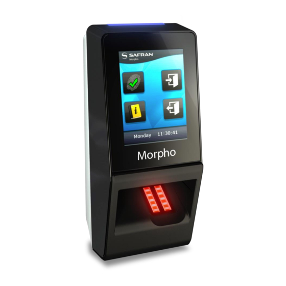
MorphoAccess® SIGMA Lite+
This document and the information therein are the property of Morpho, and must not be
copied or communicated to a third party without the prior written authorization of Morpho.
SIGMA Lite Series
MorphoAccess® SIGMA Lite
Table of Contents

Related Manuals for Safran morphoaccess sigma lite


Summary of Contents for Safran morphoaccess sigma lite
- Page 1 ® MorphoAccess SIGMA Lite Series Quick User Guide 2015_2000005700-V4 MorphoAccess® SIGMA Lite+ MorphoAccess® SIGMA Lite All descriptions, illustrations, and specifications in this brochure should be considered approximate and may relate to optional equipment or feature This document and the information therein are the property of Morpho, and must not be copied or communicated to a third party without the prior written authorization of Morpho.
- Page 2 Table of Contents Color Step Content Overview Wiring Three Communication Four ACP or SDAC Five Administration Software Seven Enrollment Eight Optional features MorphoAccess® SIGMA Lite Series – This document and the information therein are the property of Morpho, and must not be copied or communicated to a third party without the prior written authorization of Morpho.
- Page 3 Product Overview ® The MorphoAccess SIGMA Lite Series Optional Wi-Fi™ Status LED terminal has a simple and ergonomic man- Status LED USB adaptor machine interface designed for access control and Time & Attendance, with (plugged at the back fingerprint recognition, contactless card of the terminal) USB host port authentication and PIN authentication...
- Page 4 ® MorphoAccess SIGMA Lite Checklist Product packaging checklist: ITEM ® MorphoAccess SIGMA Lite or Lite+ terminal Back door equipped with cables and screws Lite Lite+ Protection Accessory (optional) Wall Mounting Plate Documentation package Electronic documentation is provided in Adobe® Acrobat® format (PDF). Adobe® Acrobat® Reader is available at http://www.adobe.com. MorphoAccess®...
- Page 5 ® MorphoAccess SIGMA Lite terminal Implementation ® To secure an access, Morpho recommends installing the MorphoAccess SIGMA Lite Series terminal as a part of a typical Access Control system, which consists of the components described below. ® The MorphoAccess SIGMA Lite Series terminal Its role is to process the access request from the user.
- Page 6 Typical Access Control Process If the user is If the result of the allowed to access check is successful to the protected On Access (user recognized ), zone, the central Request, the a message is sent access controller terminal checks to the Central returns an "access user’s access...
- Page 7 ® MorphoAccess SIGMA Lite Access Control Modes The terminal can be configured in one of the modes described in the table below Identification Authentication Multifactor Proxy Access Application that runs Application that runs Application that runs Remote application control on the terminal when on the terminal when on the terminal when that controls the...
- Page 8 Deployment Environments -10°to + 55 °C (14°to 131°F) Operating temperature Operating humidity 10 % < RH < 80 % (non condensing) -25°to + 70 °C (-13°to 158°F) Storage temperature Storage humidity 5% < RH < 95 % IP65 rated, once backdoor fixed with the 4 screws IP code General precautions ...
- Page 9 Wiring Overview RS-485, GP IN & OUT RJ-45 : Ethernet & PoE RS485_A Blue ETH TX+ Orange RS485_B Blue / Red ETH TX- Orange / White RJ-45 RS485_GND Black / Red ETH RX+ Green GPI_0 Orange ETH RX- Green / White GPI_1 Orange / Red ETH VPORT+...
- Page 10 Power Wiring Power Over Ethernet (POE): power can be provided through RJ-45 connector using a PSE (Power Sourcing Equipment) IEEE 802.3af or IEEE802.3at type 1 compliant. RJ-45 The terminal is a Class 0 (15.4W) PD (Powered Device). PoE Injector Specs Power + 12V ...
- Page 11 RS-485 Communication Wiring Block RS-232 to RS-232 RS-485 RS-485 to from the converter 1200m (4000ft) Com Port For RS-485 installations, the cable should be run in a daisy-chain configuration (i.e. converter > position 1 > position 2 > position 3, etc.). RS485_A Blue Choose one twisted pair of conductors to use for RS-...
- Page 12 Ethernet and Wireless LAN ETH TX+ Orange RJ-45 ETH TX- Orange / White ETH RX+ Green ETH RX- Green / White Wireless ETH VPORT+ Blue 4 & 5 ETH VPORT- Blue / White 7 & 8 ETH GND Drain wire (no color) Shell Use a category 5 shielding cable (120 Ohms) or better.
- Page 13 Wiegand Communication WIEGAND_IN0 Green / Red WIEGAND_IN1 White / Red WIEGAND_OUT0 Green WIEGAND_OUT1 White Wiegand In WIEGAND_LEDOUT1 Blue Wiegand Out WIEGAND_LEDOUT2 Blue / Red WIEGAND_GND Black / Red LED In WIEGAND_LEDIN (GPO_0) Yellow Three-conductor wire (shielded recommended) is required for Data 0, Data 1, and WGND. Use 18-22 AWG cable in a homerun configuration from each unit to the Access Control Panel (ACP).
- Page 14 Wiegand Communication (continued) Important Example Format Information By default, the Wiegand output format is not enabled. Type: Standard 26-bit Wiegand output must be configured before connecting to the Alt Site Code and Fail Site Code Range: 0-255 ACP. Template ID Number Range: 1-65535 Note ...
- Page 15 Single Door Access Control (SDAC) Single Door Access Control (SDAC) wiring sample : with Push Button See details on next page for relay connection RELAY_NO Yellow Deadbolt / Door strike RELAY_NC Orange RELAY_COM Grey Power supply GPI_0 Yellow Door contact GPI_1 Orange / Red Push Button...
- Page 16 Internal Relay Wiring Snubber Diode Power supply VCC < 30V Imax < 1A Deadbolt / Door strike Warning This is recommended only for small or stand-alone applications where access control panels are Push Button RELAY_NO Yellow not available. on other side RELAY_NC Orange of the door...
- Page 17 First communication with terminal (1/2) First configuration requires a network link ® The MorphoAccess SIGMA Lite Series terminal is designed to be able to run in standalone mode, but at least point to point connection between PC and terminal is necessary for the first configuration.
- Page 18 First communication with terminal (2/2) General remark for network configuration If terminal is connected to local network without DHCP server, be sure to configure the following parameters : Administration PC and all terminals shall have a different IP address (ex : 192.168.0.1; 192.168.0.2; …). ...
- Page 19 Administration with Embedded Web Server Terminal administration & User enrolment with a standard web browser The terminal’s embedded Web server enables easy configuration of the devices as well as user enrolment using a web browser on a Desktop PC, Laptop, Tablet or smart phone.
- Page 20 Administration with MorphoBioToolBox application Terminal administration with MorphoBioToolBox application Another way to configure the ® MorphoAccess SIGMA Lite Series terminal is to use a dedicated application: MorphoBioToolBox (for Windows) Please note that this application has an embedded User Guide (Help menu).
- Page 21 Software for Terminal Remote Administration ® MorphoAccess SIGMA Lite Series terminals are fully compatible with: MorphoManager application(version 8.0.3 or higher) When Legacy Morpho mode enabled, the terminal is compatible with: MEMS (version 7.3.1 or higher), The limitations in Morpho Legacy mode are described in the following document: ...
- Page 22 Fingerprint Capture Basics 1/3 Region of Interest Recommended Fingers Acquisition troubleshooting Middle Finger General recommendations Ring Finger Fore Finger Remove bandages or adhesive taining tapes from the fingerprint area Do not press or tense finger to avoid blood vessels constriction. Fingerprint image too dark : the finger is probably too moist and/or too dusty...
- Page 23 Fingerprint Capture Basics 2/3 Ideal Finger Position Incorrect Position: • Do not place the finger tip : on the bottom of the sensor, Finger or in the middle of the sensor Height Correct Position: • Align centre of finger tip with sensor centre Incorrect Position: •...
- Page 24 Fingerprint Capture Basics 3/3 Ideal Finger Position Incorrect Position: • Do not leave the finger in the air Finger • Do not bend finger upward or downward Inclination Correct Position: • Finger is parallel to sensor surface IDEAL POSITION Incorrect Position: •...
- Page 25 ® MorphoAccess SIGMA Lite Series basic MMI Yellow Purple blue green blinking blinking Waiting Access Access Place Not waiting for card granted denied finger script in card progress Move Database script script finger empty / not finished failed waiting finger MorphoAccess®...
- Page 26 ® MorphoAccess SIGMA Lite+ Series basic MMI Waiting Access Access Place USB key USB key for card granted denied finger detected removed Move script script finger finished failed MorphoAccess® SIGMA Lite Series – This document and the information therein are the property of Morpho, and must not be copied or communicated to a third party without the prior written authorization of Morpho.
- Page 27 Contactless Card Position – PIN Input ® Contactless Card Position Input PIN (MorphoAccess SIGMA Lite+) Place RF card in front of contactless card reader When defined by terminal settings, the user is required to enter his PIN code, once during enrolment process, Authentication of the user is initiated by the detection of a and at each authentication (in addition or instead of user card by the (optional) contactless card reader.
- Page 28 Contactless Card Position – Warning MorphoAccess® SIGMA Lite Series – This document and the information therein are the property of Morpho, and must not be copied or communicated to a third party without the prior written authorization of Morpho. Quick User Guide - 2015_2000005700-V4...
- Page 29 Time and Attendance feature ® (MorphoAccess SIGMA Lite+) ® MorphoAccess SIGMA Lite+ Series terminals support an optional Time and Attendance (T&A) feature. For this the terminal add a specific T&A information to each identification or authentication record stored in the embedded event log database. This information is provided by the user through a specific screen displayed during identification or authentication process.
- Page 30 Recommendations Global warning The manufacturer cannot be held responsible in case of non-compliance with the following recommendations or incorrect use of the terminal. General precautions ® Do not attempt to repair the MorphoAccess SIGMA Lite Series terminal yourself. The manufacturer cannot be held responsible for any damage/accident that may result from attempts to repair components.
- Page 31 Documentation Documents about installing the terminal ® MorphoAccess Lite Series Installation Guide, Ref. 2015_0000007248 This document describes terminal physical mounting procedure, electrical interfaces and connection procedures. Documents about administrating / using the terminal ® MorphoAccess Lite Series Quick User Guide, Ref. 2015_2000005700 This document gives a quick overview of the product and the basics of configuration and use.
- Page 32 Contacts Technical Support and Hotline India: North America Mail: [email protected] Mail: [email protected] Tel: 0120-4699900 Tel: +1 888 940 7477 Europe and rest of the world: South America Mail: [email protected] Mail: [email protected] Tel: +33 1 58 11 39 19 Tel: +1 714 575 2973 (9H00am to 5H30pm French Time, Monday to Friday) South Africa Mail: [email protected]...