LG PQNFB17C1 Installation And User Manual
V-net acs
Hide thumbs
Also See for PQNFB17C1:
- Installation & user manual (108 pages) ,
- Installation & owner's manual (118 pages) ,
- Installation & owner's manual (121 pages)
Table of Contents
Installation/User Manual
Make sure to read the cautions for safety before installation and use, and
use it correctly.
It is intended to keep protect the safety of the installer and user and to
prevent the property damage, etc.
After reading the user manual, please keep it at a place where user can
access any time.
: BACnet Gateway (ACP BACnet)
: PQNFB17C1, PQNFB17C0
*MFL67709501
P/NO : MFL67709501
www.lge.com
Table of Contents

Related Manuals for LG PQNFB17C1


Summary of Contents for LG PQNFB17C1
- Page 1 It is intended to keep protect the safety of the installer and user and to prevent the property damage, etc. After reading the user manual, please keep it at a place where user can access any time. : BACnet Gateway (ACP BACnet) : PQNFB17C1, PQNFB17C0 *MFL67709501 www.lge.com P/NO : MFL67709501...
-
Page 3: Registered Trademarks
The contents of this ACP BACnet User Guide are protected by international copyright laws, and the Computer Program Protection Act. The contents of the User Guide and the programs mentioned herein may only be used under license from LG Electronics in strict adherence to the user agreement. - Page 4 Explanatory Notes...
- Page 5 The product images and descriptions included in this manual are stated based on ACP BACnet Free volt (Model No.: PQNFB17C0). ACP BACnet Free volt (PQNFB17C0) ACP BACnet 24V (PQNFB17C1) For your records Staple your receipt to this page in case you need it to prove the date of purchase or for warranty purposes.
- Page 6 MEMO...
-
Page 7: Important Safety Instructions
IMPORTANT SAFETY INSTRUCTIONS IMPORTANT SAFETY INSTRUCTIONS READ ALL INSTRUCTIONS BEFORE USING THE APPLIANCE. Always comply with the following precautions to avoid dangerous situations and ensure peak performance of your product WARNING It can result in serious injury or death when the directions are ignored. CAUTION It can result in minor injury or product damage when the directions are ignored. - Page 8 IMPORTANT SAFETY INSTRUCTIONS Do not install where raindrop can fall. - It may cause failure of the product. Do not install the product at wet place. - It may cause failure of the product. Provided product and adaptor shall only be installed and used inside a building. - It may cause fire or failure of the product.
- Page 9 IMPORTANT SAFETY INSTRUCTIONS If the product is flooded, consult the service center or the professional installation agency. - It may cause fire or electric shock. Let the children or the old and the weak be controlled by the guardian to use. - It may cause accident or failure.
- Page 10 MEMO...
-
Page 11: Table Of Contents
Specification Setting the ACP BACnet network Starting address Setting the functions of the ACP Login and logout BACnet Home screen composition and features LG's ACP BACnet Agreement Using the Program Functional Specifications Control/Monitor ACP BACnet Schedule Auto Logic Statistics NOTES... - Page 12 MEMO...
-
Page 13: Functions And Specification
ACP BACnet FUNCTIONS AND SPECIFICATION ACP BACnet FUNCTIONS AND SPECIFICATION ACP BACnet is the central controller that can manage up to 256 equipments in one space individually or as combined. ACP BACnet can monitor or control the equipments installed in each room of the building from the places such as the management office of a building or the administration office of a school. - Page 14 ACP BACnet FUNCTIONS AND SPECIFICATION Embedded web server function window using Internet Explorer, the central control program in ACP BACnet web server is automatically run, and the functions of various contents can be used. Internet Internet Explorer Controlling of up to 256 air conditioner indoor units Monitoring of error and operation status Controlling the peak power / demand power System setting function...
-
Page 15: Bacnet
ACP BACnet Quick Manual Power Supply Adaptor Power Cord ACP BACnet Installation/User Input: 100~240V 250V AC, 3A Manual CD AC 50/60Hz 3.33A Output: DC 12V 3.33A, 40W MAX Notes Power Supply Adaptor and Power Cord are not included in PQNFB17C1. -
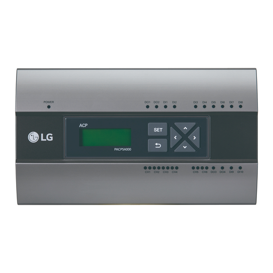
Page 16: Name Of Each Part Of Acp
ACP BACnet FUNCTIONS AND SPECIFICATION Names of each part of ACP BACnet ACP BACnet is composed as follows. PQNFB17C0 PQNFB17C0 PQNFB17C0 PQNFB17C0... -
Page 17: Specification
ACP BACnet FUNCTIONS AND SPECIFICATION Notes No. 3 and No. 4 may be different for each model. Number Item Description Cover Front cover of the ACP BACnet RS-232 console port Reserved communication port Adaptor connection Jack for DC 12V to connect to the power supply adaptor jack (not supported by PQNFB17C0.) AC24V port for power connection (not supported by... -
Page 18: Acp Bacnet Hardware
ACP BACnet FUNCTIONS AND SPECIFICATION ACP BACnet Hardware Specification ACP BACnet hardware specification is as follows. Category Description Boundary of usage temperature 0°C~40°C i.MX515 32Bit 800MHz speed 128MB DDR2 SDRAM * 2EA 4GB i-NAND Flash Ethernet 10 / 100 BASE-T USB : USB Host (SW upgrade, data backup) mini USB Device (Debug) Communication ports... -
Page 19: Starting
Starting Starting Login and logout The following explains how to log in/out ACP BACnet. Connected to the ACP BACnet How to Connect to the ACP BACnet is as follows. Connected to theACP BACnet enter the IP address of the ACP BACnet in the Internet Browser. Login You can login as follows. - Page 20 Starting Logout You can logout as follows. On the top right of the ACP BACnet screen, click the [Logout] button. You are now logged out.
-
Page 21: Home Screen Composition And
Starting Home screen composition and features The following explains the home screen composition and features. Number Item Description Running Status Checks if all the devices are operating, has stopped, or (Unit) has already been checked. Check the current date and time. Time (You need Internet connection to check the weather.) Check the registered schedules in chronological order. - Page 22 MEMO...
-
Page 23: Control/Monitor
Using the Program Using the Program The following explains how to use the ACP BACnet functions. Control/Monitor Control/Monitoring is managing multiple devices collectively as one. The following explains the Control/Monitor menu options. Control/Monitoring screen composition and features The following explains Control/Monitoring screen composition and features. Number Item Description... - Page 24 Using the Program Number Item Description Monitoring Screen Check the control status of a device. Display the device control menu. The device control box shows different menus Device Control Box depending on the device. (For more on Control Menu per Device on page 17) View Type Control/Monitor menu has three types of views (icon, simple, and detailed).
- Page 25 Using the Program Simple The control device and operation mode are displayed only. Number Item Description The color of the box indicates the current operation Operation Mode mode. Device Icon The device to be controlled is indicated as an icon. Details All properties of the control device are tabulated in details.
- Page 26 Using the Program Monitoring screen colors and icons Box colors and operation mode per icon Color Icon Operation Mode Cooling Ventilation, General (Blue) Heating Ventilation, Electric Heat (Orange) Dehumidification (Navy) (Sky Blue) Power Saving (Green) Auto Ventilation, Auto (Purple) ON & Short (Yellow) OFF &...
- Page 27 Using the Program Device status icon Icon Device Status Filter Exchange Full Lock On Peak/Demand Control Schedule Control device icon Icon Device Type Indoor Device Ventilators AWHP Chiller DOKIT...
-
Page 28: Device Control
Using the Program Device Control You can control the devices as follows. From the main menu, click the [Control/Monitor] menu icon. Click the device group you want to control from the group list. The monitoring screen for the device is displayed. Click the device you want to control. -
Page 29: Environment
Using the Program Control Menu per Device The control box menu differs depending on the device. The following shows the control box menu per device. Indoor Device The following is the indoor unit control menu and features. Item Description [ON] Button: Starts the operation of the device. Operation [Off] Button: Stops the operation of the device. - Page 30 Using the Program Indoor unit fine control Item Description [ON] Button: Starts the operation of the device. Operation [Off] Button: Stops the operation of the device. Click to set the temperature. [COOL] Button: Operates with Cooling Mode. [HEAT] Button: Operates with Heating Mode. [AUTO] Button: Evaluates the operating environment conditions and automatically sets the optimum temperature.
- Page 31 Using the Program Item Description [HardLock] Button: Disables remote control for all features. [Clear] Button: All functions are unlocked. [ModeLock] Button: Disables remote control for local mode setting. [Clear] Button: Mode is unlocked. Partial Lock [FanLock] Button: Disables remote control for local fan speed setting. [Clear] Button: Fan speed is unlocked.
- Page 32 Using the Program Item Description (The setback function works well with "Heat Recovery" model. For other models, it may not work properly.) Set the setback function to control the proper room temperature when the Setback indoor unit is turned off. [ON] Button: Enable temperature limits [OFF] Button: Disable temperature limits Cooling Start...
- Page 33 Using the Program ERV Fine Control Item Description [ON] Button: Starts the operation of the device. Operation [OFF] Button: Stops the operation of the device. Click to set a desired temperature (the ventilator is not activated). [AUTO] Button: Evaluates the operating environment conditions and automatically sets the optimum temperature.
- Page 34 Using the Program ERV DX The following is the ERV DX control menu and features. Item Description [ON] Button: Starts the operation of the device. Operation [Off] Button: Stops the operation of the device. GoTo [Schedule ] Button: Move to Schedule menu. Room Display the current temperature.
- Page 35 Using the Program ERV DX Item Description [ON] Button: Starts the operation of the device. Operation [OFF] Button: Stops the operation of the device. Click to set the temperature. [AUTO] Button: Evaluates the operating environment conditions and automatically sets the optimum temperature. [HEX] Button: Air supply and emissions are all ventilated through the heat Mode exchanger.
- Page 36 Using the Program Item Description [Drift] Button: Reduces energy consumption by operating in the most efficient method possible. [Quick] Button: Operates at maximum performance to prevent the room's contaminated or humid air from entering other spaces. [Clear] Button: Disables power saving / rapid operation. Additional [Heater On] Button: Enables the heater function to heat the room.
- Page 37 Using the Program The following is the AHU control menu and features. Item Description [ON] Button: Starts the operation of the device. Operation [Off] Button: Stops the operation of the device. GoTo [Schedule ] Button: Move to Schedule menu. Room Display the current temperature.
- Page 38 Using the Program AHU Fine Control Item Description [ON] Button: Starts the operation of the device. Operation [OFF] Button: Stops the operation of the device. Click to set the temperature. [COOL] Button: Operates with Cooling Mode. [HEAT] Button: Operates with Heating Mode. [FAN] Button: Purifies the air.
- Page 39 Using the Program DOKIT The following is the DOKIT control menu and features. Item Description [ON] Button: Starts the operation of the device. Operation [Off] Button: Stops the operation of the device. GoTo [Schedule ] Button: Move to Schedule menu. AWHP The following is the AWHP control menu and features.
- Page 40 Using the Program AWHP Fine Control Item Description [ON] Button: Starts the operation of the device. Operation [OFF] Button: Stops the operation of the device. [ON] Button: Enables the hot water function. Hotwater [OFF] Button: Disables the hot water function. [Set] Button: Disables remote control for all features.
- Page 41 Using the Program The following is the DO control menu and features. Item Description [SHORT] Button: Short signal output. Operation [OPEN] Button: Open signal output. GoTo [Schedule ] Button: Move to Schedule menu.
- Page 42 Using the Program Registering Floor Plan In the Control/Monitor menu, you can register floor plans to identify and locate each device and device group. On the floor plan, you can register space information as well as the location where a device is installed.
- Page 43 Using the Program [Add Drawing] button. The Open Floor Plan window is displayed. Select a desired floor plan from the Open Floor Plan window, then click [Confirm]. The floor plan image is displayed.
- Page 44 Using the Program In the device list, select a device you want to display on the floor plan and click the device location on the plan. To delete a device from the plan, double-click its icon. To complete the registration of the floor plan, click the [Apply] button. Notes To add a floor plan, put image file to USB root directory or /mnt/flash/map directory.
- Page 45 Using the Program Checking Floor Plan In Control/Monitoring, you can check floor plans. On the floor plan, you can register space information as well as the location where a device is installed. In the main menu, click the [Control/Monitor] menu icon. Select the device group you want to monitor from the group list.
- Page 46 Using the Program Editing the Floor Plan You can edit a registered floor plan. In the main menu, click the [Control/Monitor] menu icon. Select the device group you want to monitor from the group list. The monitoring screen for the device is displayed. Click [Drawing] button.
- Page 47 Using the Program To change the location of a device, click the icon of the device and then click the location to which you want to move that device. To complete floor plan editing, click the [Apply] button. Notes To add a floor plan, put image file to USB root directory or /mnt/flash/map directory. To add a floor plan, you can only use jpg, gif, or png file formats.
- Page 48 Using the Program Deleting the Floor Plan You can delete a registered floor plan. In the main menu, click the [Control/Monitor] menu icon. Select the device group you want to monitor from the group list. The monitoring screen for the device is displayed. Click [Drawing] button.
- Page 49 Using the Program Monitoring a Device You can check the control state of registered devices. In the main menu, click the [Control/Monitor] menu icon. Select the device group you want to monitor from the group list. The monitoring screen for the device is displayed. Click a device you want to monitor.
-
Page 50: 38 Schedule
Using the Program Schedule The Schedule feature allows you to program the behavior of the devices. If a device must adhere to a certain schedule, you can program the device to operate only at scheduled times. Scheduled devices do not activate unless programmed to do so and are managed centrally. This can significantly reduce energy consumption. - Page 51 Using the Program Number Item Description [Add a Schedule] Registers new schedules. Button Creating Schedules You can configure and add a schedule for a device. In the main menu, click [Schedule] menu icon. [Add a Schedule] Button. The Add Schedule window opens. In the group list, click a device for which a schedule is applied.
- Page 52 Using the Program Configure the schedule information that controls the device. Item Description Schedule Name Click the input box. Enter the name of the schedule.. Click the time area and then the [+]/[-] button to select the desired time. Time Click the [AM]/[PM] button to select before or after midday.
- Page 53 Using the Program Click the device icon of the applied device. The control configuration window for the device is displayed. The control configuration window differs depending on the device. Configure the device control status, then click the [Confirm] button. The control list configured in the Command Summary area is displayed. To complete the schedule configuration, click the [Confirm] button.
- Page 54 Using the Program Checking Schedules You can check registered schedules. In the main menu, click the [Schedule] menu icon. In the Date area, click the [ ]/[ ] button to select a schedule search period. The number of schedules are displayed for the selected date. To check schedule details, click a schedule you want to check in the schedule list.
- Page 55 Using the Program Editing Schedules You can modify the content of a registered schedule as follows. In the main menu, click the [Schedule] menu icon. Click a schedule you wish to modify from the schedule list. Schedule details are displayed. Click the [Edit] button.
- Page 56 Using the Program Deleting Schedules You can delete a registered schedule as follows. In the main menu, click the [Schedule] menu icon. Click a schedule you wish to delete from the schedule list. Schedule details are displayed. Click the [Delete] button. When you are prompted to confirm the deletion, click [Confirm].
- Page 57 Using the Program Auto Logic Auto Logic allows the system to automatically control the power consumption of external devices. You can also set the indoor temperature to automatically adjust to outdoor conditions or activate devices for certain periods of time. Notes If you set a device control value in the auto logic status view, the device can operate based on that value.
- Page 58 Using the Program Editing Groups The auto logic designates the registered devices as a group and controls them by group. The following explains how to create groups and how to edit the created groups. Adding Groups You can create a group as follows. In the main menu, click the [AutoLogic >...
- Page 59 Using the Program In the non-registered device area, click a device to add to the new group and click the [Add] button. The selected device is moved to the registered device area. Notes Peak control is only limited to indoor devices, therefore you cannot register other devices such as the ventilator, AHU or AWHP.
- Page 60 Using the Program Changing Group Name You can change the name of a registered group as follows. In the main menu, click the [AutoLogic > Peak Control] menu icon. Click the [Edit Group] button. The screen converts to Edit Group. In the group list, click a group whose name you want to change and click the [Rename] button.
- Page 61 Using the Program Deleting Groups You can delete a registered group. In the main menu, click the [AutoLogic > Peak Control] menu icon. Click the [Edit Group] button. The screen converts to Edit Group. In the group list, click a group to be deleted and click the [Del Group] button. When you are prompted to confirm the deletion, click [Confirm].
- Page 62 Using the Program Configuring Peak Control You can configure Peak Control as follows. In the main menu, click the [AutoLogic > Peak Control] menu icon. Select the control status in the control configuration area. Number Item Description Group List Displays the device group list and group priority. Configures Peak Control configuration and details.
- Page 63 Using the Program Number Item Description (Operation Status - Priority Control selected) Operation - [Run] Button: Operates the device. - [Stop] Button: Stops the operation of the device. Shift Time(Min.): Click to set the time in minutes to force the operation to switch over. Target ratio(%): Click or drag to set the target Control...
- Page 64 Using the Program Configuring Priority In the main menu, click the [AutoLogic > Peak Control] menu icon. In the group list, click the priority icon ( ) of the group in question and then select a desired priority. Notes Basically, a newly added group has the highest priority. If a group is added, re-configure the priority for all groups.
- Page 65 Using the Program Checking Peak Control Status You can check the Peak Control configuration status as follows. In the main menu, click the [AutoLogic > Peak Control] menu icon. Check how Peak Control is configured.
- Page 66 Using the Program Item Description Configure Peak Controls. Operation Status - Can be configured in [Environment > Advance Setting]. - Priority: Controls based on group priority - Outdoor unit capacity control: Controls based on outdoor unit capacity limit. (Operation Status - Priority Control selected) Operation Control - [Run] Button: Operates the device.
- Page 67 Using the Program Checking Demand Control Status You can check the Peak Control configuration status as follows. In the main menu, click the [AutoLogic > Demand Control] menu icon. Check how Demand Control is configured. Number Item Description Comm. Status Displays the communication status between demand with Demand controller and ACP BACnet.
- Page 68 Using the Program Number Item Description (Operation Status - Priority Control selected) Operation - [Operate] Button: Operates the device. - [Stop] Button: Stops the operation of the device. Shift Time(Min.): The cycle by which the operation switches over. Control Target ratio(%): Displays the target operation rate. Configuration Current Running(%): Displays the current rate.
- Page 69 Using the Program Time-limit Operation The time-limit operation is to limit the amount of time the devices (indoor unit, ventilator, DOKITs, AWHP, and AHU) are running individually. By setting the device operation time in advance, you can control for how long a device works and have it stop automatically. Editing Groups The auto logic designates the registered devices as a group and controls them by group.
- Page 70 Using the Program In the group list, click the group added in Step 4. In the non-registered device area, click a device to add to the new group and click [Add] button. The selected device is moved to the registered device area. Notes For the time-limit operation, you cannot register DI/DO.
- Page 71 Using the Program Changing Group Name You can change the name of a registered group as follows. In the main menu, click the [AutoLogic > TimeLimitControl] menu icon. Click the [Edit Group] button. The screen converts to Edit Group. In the group list, click a group whose name you want to change and click the [Rename] button. Enter a new group name and click the [Confirm] button.
- Page 72 Using the Program Deleting Groups You can delete a registered group. In the main menu, click the [AutoLogic > TimeLimitControl] menu icon. Click the [Edit Group] button. The screen converts to Edit Group. In the group list, click a group to be deleted and click the [Del Group] button. When you are prompted to confirm the deletion, click [Confirm].
- Page 73 Using the Program Configuring Time-Limit Operation In the main menu, click the [AutoLogic > TimeLimitControl] menu icon. In the group configuration status area, click a group to be controlled. The device list, status information, and condition details of the group are displayed. Select the control status in the conditions configuration area.
- Page 74 Using the Program To run the time-limit operation on the group, in the group configuration operation status area, click the [disable] button. The button changes to [enable]. To complete the configuration, click the [Apply] button. Notes If you change the operation stop standby time, it takes about 15 seconds to apply it.
- Page 75 Using the Program InterLocking You can integrate the system with external devices, like fire alarms, to halt the operation of all indoor units and ventilators. For InterLocking, you should create a pattern for devices and apply the control configuration. The following explains how to create and manage a pattern and control device integration.
- Page 76 Using the Program In the non-registered device area, click a device to be registered and click the [Add] button. In the input device list, click the device you want to control. Select a control status in the control configuration area. Click the [Output Device] tab.
- Page 77 Using the Program Editing Pattern You can edit a pattern as follows. In the main menu, click the [AutoLogic > InterLocking] menu icon. Select a pattern and click the [Edit] button. The pattern editing screen opens. Modify the pattern configuration information and click the [Apply] button. Deleting Pattern You can delete a pattern as follows.
- Page 78 Using the Program Checking InterLocking In the main menu, click the [AutoLogic > InterLocking] menu icon. Click a pattern for which you want check the device integration. The device integration status for the pattern is displayed.
- Page 79 Using the Program Statistics The following explains how to use statistics and graphs to check the power consumption and operation time of a device. Statistics Screen Composition and Features The following explains the statistics screen composition and features. Number Item Description Group List Displays the device group list.
- Page 80 Using the Program Number Item Description Selects the period for which you want to query statistics details for daily. Query Period Selection Area The start date should be no more than 31days before the end date. Statistics data per period: Displays power consumption per unit of query or operation time Displays Statistics statistics and graphs.
- Page 81 Using the Program Check the statistics details in the statistics information display area. To change the statistics information view type, click the [Table] or [Graphic] button. Notes The statistics data is stored up to 6 months. Notes Devices which can query the Run Time: Indoor units Devices which can query the Power consumption: devices which can be used with the PDI (For further information about the devices can be used with the PDI, please refer to the PDI manual.)
- Page 82 Using the Program Report The following explains how to query the device control information or error information. Report screen composition and features The following explains the report screen composition and features. Number Item Description Selects report query items. [Total] Button: Queries all reports regarding control and error.
- Page 83 Using the Program Querying Report You can query the device control or error report as follows. In the main menu, click the [Report] menu icon. In the report item, click an item for which you want to query a report. [Total] Button: Queries all reports regarding control and error.
- Page 84 Using the Program Installing You can add a device or change the settings of a registered device. Registering Device After installing ACP BACnet, log into ACP BACnet to register the devices to be connected. ACP BACnet can register a device by using one of two methods. Registering Device Automatically Registering Device Manually Notes...
- Page 85 Using the Program When you are prompted to confirm the setting, click [Confirm]. It takes 5 to 10 minutes to register a device automatically. To save the searched devices, touch the [Apply] button. Device registration is completed. 2 DIs and 2 DOs is always added to the Unit Status.
- Page 86 Using the Program Registering Device Manually Devices connected to ACP BACnet can be registered by the user by entering relevant information. You can register a device manually as follows. In the main menu, click the [Installing] menu icon. Click the [Installing] tab. Type the device information and click the [Insert] button.
- Page 87 Using the Program Changing Device You can change the settings of registered devices. In the main menu, click the [Installing] menu icon. Click the [Installing] tab. Click a device to be changed in the device list. The device information is displayed in the device information input box. Type the device information and click the [Modify Unit] button.
- Page 88 Using the Program Managing Device The following explains how to manage the information for a device added to the system. Adding Groups Follow these steps to add a new group. In the main menu, click the [Installing] menu icon. Click the [Grouping] tab. Click the [Add Group] button.
- Page 89 Using the Program In the non-registered device area, click a device to add to the new group and click the [Add] button. The selected device is moved to the registered device area. To complete group creation, click the [Apply] button. When all non-registered devices are registered, the [Apply] button is enabled.
- Page 90 Using the Program Changing Group Name You can change the name of a registered group as follows. In the main menu, click the [Installing] menu icon. Click the [Grouping] tab. In the device management list, click a group whose name you want to change and click the [Rename] button.
- Page 91 Using the Program Deleting Groups You can delete a registered group. In the main menu, click the [Installing] menu icon. Click the [Grouping] tab. In the device management list, click a group to be deleted and click the [Del Group] button. When you are prompted to confirm the deletion, click [Confirm].
- Page 92 Using the Program Environment The following explains how to configure the system environment for user convenience and how to check an already configured environment. General Setting The following explains how to configure the general system environment. Item Description Configures the language displayed on the screen Language (Korean)/ English).
- Page 93 Using the Program Language Configures the language displayed on the screen. In the main menu, click the [Environment] menu icon. In the settings list, click General Setting. In the detailed settings list, click Language. Click a language you want. The selected language is applied as the system language. Time setting You can configure the time used for the system as follows.
- Page 94 Using the Program Date setting You can configure the date used for the system as follows. In the main menu, click the [Environment] menu icon. In the Settings list, click General Setting. In the detailed settings list, click Date setting. Modify the pattern configuration information and click the [Apply] button.
- Page 95 Using the Program Initial date for statistics Statistics Reference Date is the date for calculating the indoor unit's operation time by month. The operation time from this date through the previous date to the same date of the next month is calculated and provided as statistical data.
- Page 96 Using the Program Holiday setting(The day schedule is not work) The following explains how to register an exception date or how to delete a registered date. Adding Exception Date You can add a desired exception date as follows. In the main menu, click the [Environment] menu icon. In the Settings list, click General Setting.
- Page 97 Using the Program Deleting Exception Date You can delete a registered exception date as follows. In the main menu, click the [Environment]menu icon. In the Settings list, click General Setting. In the detailed settings list, touch Holiday setting(Days in which the schedule is ignored). The Exception Date Configuration window opens.
-
Page 98: Advance Setting
Using the Program Advance Setting The following explains how to configure the functions necessary for device operation. Item Description Master: ACP BACnet must be set to only master. LGAP setting Slave: Not used. Peak Control: You can use the peak control feature in the auto logic menu. - Page 99 Using the Program LGAP setting ACP BACnet can interface with another central controller to control a device. You can configure the interface type with other devices as follows. In the main menu, click the [Environment] menu icon. In the Settings list, click Advance Setting. In the detailed settings list, click LGAP setting.
- Page 100 Using the Program Set the operation mode You can configure the operation type as follows. In the main menu, click the [Environment] menu icon. In the Settings list, click Advance Setting. In the detailed settings list, click Set the operation mode. Click an operation type you want.
- Page 101 Using the Program Update S/W You can upgrade the current version of software as follows. Notes To update the software, you need a USB memory stick which has patch.tar file in the ramdisk folder. Connect the USB memory to ACP BACnet. In the main menu, click the [Environment] menu icon.
- Page 102 Using the Program DB backup You can backup the database stored in the system to USB memory as follows. Connect the USB memory to ACP BACnet. In the main menu, click the [Environment] menu icon. In the Settings list, click Advance Setting. In the detailed settings list, click DB backup.
- Page 103 Using the Program Customer Setting Only the administrator account can change user environments. Item Description Change Password Only the administrator account can change the password. Add user Add up to 30 new system users. [Delete] Button: Deletes a user. User Management [Edit] Button: Changes user information.
- Page 104 Using the Program Change Password The administrator account can change a password as follows. In the main menu, click the [Environment] menu icon. In the Settings list, click Customer Setting. In the detailed settings list, click Change Password. After entering the current and new passwords, click [Confirm]. Current P/W: Enter the current password.
- Page 105 Using the Program Add user You can add a user as follows. In the main menu, click the [Environment] menu icon. In the Settings list, click Customer Setting. In the detailed settings list, click Add User. When the system password input window appears, enter the password and click [Confirm]. When the Add a New User window appears, enter the user information and click [Confirm].
- Page 106 Using the Program User Management The following explains how to delete a registered user or edit user information. Deleting User Information You can delete a registered user's information as follows. In the main menu, click the [Environment] menu icon. In the Settings list, click Customer Setting. In the user list, click the [Delete] button for the user information you want to delete.
- Page 107 Using the Program Editing User Information You can edit a registered user's information as follows. In the main menu, click the [Environment] menu icon. In the Settings list, click Customer Setting. In the user list, click the [Edit] button for the user information you want to edit. When the system password input window appears, enter the password, click [Confirm].
- Page 108 Using the Program When the Edit User window appears, enter the user information and click [Confirm]. The updated user information is applied. To complete user edit, click [Confirm].
- Page 109 Installing ACP BACnet Installing ACP BACnet Installing ACP BACnet This chapter describes how to install the ACP BACnet to use. In order to use the ACP BACnet, the installation should be performed by the following order. STEP 1. Check the cautions during the ACP BACnet installation Before installing the ACP BACnet, check the cautions.
- Page 110 Installing ACP BACnet Caution Installing the ACP BACnet The ACP BACnet installation work needs the professional technique. Therefore, the installation described in this chapter should be performed by the certified installation professional. Consult the service center or the professional installation agency certified by us about any question or request related to the installation.
- Page 111 Installing ACP BACnet Setting the indoor unit address By considering the entire installation configuration connecting to one ACP BACnet, set the address to each indoor unit not to be overlapped. 00~FF in hexadecimal can be set to the indoor unit address. Notes Assigning indoor and outdoor unit number If the outdoor unit product is Multi V, it is...
- Page 112 Installing ACP BACnet When the ACP BACnet is interconnected with the AC Manager, the ventilator can be installed together and controlled. The above figure shows the example that sets the addresses of 30 and 31 to the ventilators and connects to the ACP BACnet. Notes How to set the central control address of the indoor unit The central control address setting method may be different for each indoor unit product or...
- Page 113 Installing ACP BACnet Setting the PI485 and connecting the cable After setting the address of the indoor unit, install the PI485 and set the DIP switch. And then, connect the RS485 cable for communication with the ACP BACnet. Notes Installing the PI485 Installing the PI485 depends on the outdoor unit.
- Page 114 Installing ACP BACnet The following figure is an example of connecting several PI485 with each other to connect to one ACP BACnet. PQNFB17C0...
- Page 115 Installing ACP BACnet Installing ACP BACnet and connecting cables After setting PI485, the ACP BACnet shall be installed in an adequate place, and RS-485 cable shall be connected for the communication with PI485. And, Ethernet cable (LAN cable) shall be connected for the connection with internet or AC Manager. To fix the ACP BACnet, the following 2 methods may be used.
- Page 116 Installing ACP BACnet Installing the ACP BACnet in DIN RAIL ACP BACnet can be installed in DIN RAIL with width 35mm and height 7.5mm. Proceed as the follows to install the ACP BACnet in an adequate place. The installation method of the ACP BACnet is explained here with the example of installing the ACP BACnet in DIN RAIL.
- Page 117 Installing ACP BACnet Fixing the ACP BACnet to the wall ACP BACnet can be installed by fixing to the wall. To install the ACP BACnet in an adequate place, proceed according to the following explanation. It explains here on how to install the ACP BACnet with the example of installing the ACP BACnet on the wall.
- Page 118 Installing ACP BACnet Information: Connecting RS-485 of the ACP BACnet Up to 16 outdoor units can be connected to one RS-485 port of the ACP BACnet, and up to 256 indoor units can be connected to one ACP BACnet. If there are many outdoor units to connect, the outdoor unit connections shall be appropriately connected to CH1 to CH4 in BUS format.
- Page 119 Installing ACP BACnet Connecting Ethernet cable (LAN cable) to the ACP BACnet After connecting the ACP BACnet and RS-485 cable, Ethernet cable shall be connected to the ACP BACnet. ACP BACnet may be connected to hub through Ethernet cable, or directly to AC Manager. Connecting the ACP BACnet and hub It is the case of connecting the ACP BACnet to the basic internet network installed at the site, and it is generally connected to the hub.
- Page 120 Installing ACP BACnet Setting the ACP BACnet network address After connecting the ACP BACnet to various devices via the cable, the network environment of the ACP BACnet should be set by driving the ACP BACnet. The following information should be set for using the ACP BACnet.
- Page 121 Installing ACP BACnet Turning on the ACP BACnet Turn on the ACP BACnet to set the network environment of the ACP BACnet. When the power switch is turned on, the ACP BACnet booting screen is displayed on the LCD as shown at the following figure, and when booting is completed, the initial ACP BACnet screen is displayed.
- Page 122 Installing ACP BACnet Entering into the environment setup mode Press [SET] button of the ACP BACnet to enter into the environment setup mode of the ACP BACnet. When the [SET] button is pressed for the first time, the menu to set the IP address is displayed as shown below.
- Page 123 Installing ACP BACnet Caution [Function] menu is used by the system air conditioner service technician, so user shallnever use this function. If this function is incorrectly used, it may cause disorder of the ACP BACnet. How to set network address DOWN To change the network setting, locate the arrow on the corresponding setting position, and press [SET] button to enter the corresponding setting screen.
- Page 124 Installing ACP BACnet The network address consists of four 3-digit numbers. In case of setting the network address, the, name of the related address is displayed on the LCD of the ACP BACnet, and press Up/Down/Left/ [Set IP Address] 192.168.000.000 Click button [Set IP Address]...
-
Page 125: Network Info
Installing ACP BACnet Setting IP address For user to use the functions of the ACP BACnet through the web, a unique IP address may be assigned to the ACP BACnet or dynamic IP setting may be used. The next is how to set fixed IP address. - Page 126 Installing ACP BACnet Using dynamic IP using DHCP For user to use the functions of the ACP BACnet through the web, a unique IP address may be assigned to the ACP BACnet or dynamic IP setting may be used. The next is how to set dynamic IP address. Please proceed according to the order.
-
Page 127
Installing ACP BACnet Checking ACP BACnet access It checks whether the ACP BACnet network address setting is properly done. You can check the possibility of accessing the ACP BACnet through PING test. You can open the following DOS window through Windows "Start", "Run", "cmd" input. In DOS screen, input "ping
"... - Page 128 Installing ACP BACnet Notes When you connected the ACP BACnet and PC through a cross cable, but you cannot access the ACP BACnet Check IP address of the ACP BACnet and IP address of the PC. if the first three digits of the IP address of the PC is the same as the first three digits of the IP address of the ACP BACnet.
- Page 129 Installing ACP BACnet Setting the functions of the ACP BACnet The following functions can be set by using the menu of the ACP BACnet: Select Peak or Demand Setting the attributes of CH6 Fire Alarm function Fahrenheit/Celsius setting function Device ID setting function Vnet number setting function Foreign Device register function Before setting the functions of the ACP BACnet...
- Page 130 Installing ACP BACnet Selecting Peak or Demand The ACP BACnet offers the function to manage the power consumed by the connected air conditioner, by which the electric charges can be effectively saved. The ACP BACnet offers two functions to limit the maximum power consumption of the air conditioner as follows: Peak: The maximum power consumption of the air conditioner can be managed by setting the maximum usage operation ratio in the ACP BACnet.
- Page 131 Installing ACP BACnet Change the power control method as follows: When you press [SET] of the ACP BACnet to select [Contents], and press [SET] button again. While [Peak/Demand] is selected, pressing [SET] button will display the screen to select peak or demand method. Network Info Contents >...
- Page 132 Installing ACP BACnet Setting whether to use FireAlarm function ACP BACnet provides Fire Alarm function. After connecting the fire sensor to ACP BACnet DI1, if the fire sensor detects fire, it stops the operations of all connected equipments except the Chiller. Caution Fire Alarm interface To use the Fire Alarm function, fire sensor needs to be connected to ACP BACnet DI1.
- Page 133 Installing ACP BACnet Setting whether to use CH6 function To connect to the Chiller from the ACP BACnet, M (Chiller) shall be selected in CH6 USAGE. D (demand controller) setting is not used. When you press the [SET] button of the ACP BACnet, menu screen will be displayed. , and press [SET] button again.
-
Page 134: Software Update
When it is necessary to update the ACP BACnet software, it must be carried out by the specialized service technician. Software update can be done with USB memory. Proceed in the following order. At this time, only one S/W file must be put. (New version software file can be downloaded from LG Electronics System Air Conditioner homepage.) - Page 135 Installing ACP BACnet E: may be changed.
- Page 136 Installing ACP BACnet Press [SET] button of the ACP BACnet. Select [Function] menu, and press [SET] button. Select [S/W update] menu, and press [SET] button again. To run the software update, press [SET] button again. Wait while software is running. After completing the update, press [SET] button to restart the ACP BACnet.
-
Page 137: Data Backup
Installing ACP BACnet Data backup If ACP BACnet data backup is necessary, it must be carried out by the specialized service technician. Data backup can be done with USB memory or SD card. Proceed in the following or der. Insert USB memory or SD card into the ACP BACnet. (Refer to software update for USB memory insertion.) - Page 138 Installing ACP BACnet Press [SET] button of the ACP BACnet. Select [Function] menu, and press [SET] button. Select [DB back up] menu, and press [SET] button again. Select [USB] or [SD card], and press [SET] button. After completing backup, remove USB memory. Network Info Contents >...
- Page 139 Installing ACP BACnet Data recovery If ACP BACnet data recovery is necessary, it must be carried out by the specialized service technician. Data recovery can be done with USB memory or SD card. Proceed in the following order. Save the database file to recover in USB memory or SD card.
- Page 140 Installing ACP BACnet Insert USB memory or SD card into the ACP BACnet. (Refer to software update and data backup) Press [SET] button of the ACP BACnet. Select [Function] menu, and press [SET] button. Select [DB recover] menu, and press [SET] button again. Select [USB] or [SD card], and press [SET] button.
- Page 141 Installing ACP BACnet RS-485 data logging If ACP BACnet RS-485 data logging is necessary, it must be carried out by the specialized service technician. Data logging can be done with SD card. Proceed in the following order. Insert SD card into the ACP BACnet. (Refer to data backup) Press [SET] button of the ACP BACnet.
- Page 142 Installing ACP BACnet Register Foreign Device In [Register FD] IP, PORT, TTL, and Activate of Foreign Device are displayed in the initial screen of [Register button. To change the Foreign Device setting, locate the arrow on the corresponding setting position, and press [SET] button to enter the corresponding setting screen.
- Page 143 Installing ACP BACnet Example of TTL setting Network Info Contents Function > Register FD Click button [Register FD] IP 000.000.000 PORT : 00000 > TTL : 00000 ON : 0 Click button [Set FD TTL] 000036000 Example of Foreign Device Activate setting Network Info Contents Function...
- Page 144 MEMO...
- Page 145 BMS Engineering Creating of the Points. This is NOT to be done by LG since it is directly related to the BMS side. The BMS engineer is to carry out the engineering of the Point, however LG is responsible for providing the method of how the Points are calculated.
- Page 146 LG's ACP BACnet Agreement Notes After the LG's ACP BACnet agreement part, please consult with the experts of BMS. BACnet PQNFB17C0 ACP BACnet Diagnosis 1. Creating of indoor and vent points. 2. Test of all units and operations. LG-NET...
-
Page 147: Functional Specifications
The ACP BACnet, in response to the requests from the BMS (Building management system which supports BACnet-ANSI/ASHRAE135 protocol), status information of A/C/vent that are connected to the ACP BACnet's internal LG-NET will be sent in BACnet service form, and BACnet client provides a function that transmits control command to the A/C/vent system. - Page 148 Functional Specifications ACP BACnet Objects - ACP BACnet/IP ACP-BAC Point List : Indoor Unit One indoor unit has a Point List as follows.
- Page 149 Functional Specifications ACP BACnet...
- Page 150 Functional Specifications ACP BACnet ACP-BAC Point List : Ventilation One Ventilation has a Point List as follows.
- Page 151 Functional Specifications ACP BACnet...
- Page 152 Functional Specifications ACP BACnet ACP-BAC Point List : AHU...
- Page 153 Functional Specifications ACP BACnet...
- Page 154 Functional Specifications ACP BACnet...
- Page 155 Functional Specifications ACP BACnet...
- Page 156 Functional Specifications ACP BACnet...
- Page 157 Functional Specifications ACP BACnet ACP-BAC Point List : AWHP One AWHP unit has a Point List as follows.
- Page 158 Functional Specifications ACP BACnet...
- Page 159 Functional Specifications ACP BACnet Object Type Instance Number Object ID Reserved Device No. Product Unit No. Point No. Product Type(Indoor:0, Vent:1 AHU:2, ODU:3, AWHP:4) **Device : Group of Product units(16EA) Example of Point Table The point table below is passed to BMS, and BMS registers the object. Case Indoor Object Device...
- Page 160 Functional Specifications ACP BACnet Object Device Product Address Point Instance No. Name Type Object Device Product Address Point Instance No. Name Type Case AHU Object Device Product Address Point Instance No. Name Type...
- Page 161 Functional Specifications ACP BACnet Detailed Explanation of Object Common to All Objects Objects related to the air conditioner in communication are treated on the ACP BACnet as described below. Air Conditioner in Normal Communication - Other ACP BACnet devices can access each object related to the air conditioner. Air Conditioner Unconnected - It seems to other ACP BACnet devices that no objects related to the air conditioner exist.
- Page 162 Functional Specifications ACP BACnet Lock (Setting) Point number: 3 Object name: LockCommand_XXX (XXX: Indoor/Vent/AHU address) Object type: Binary Output Meaning: This object is used to set the Lock of the A/C's control authority. Present_Value property: ACTIVE: Lock (Restricted) INACTIVE: Unlock (Not restricted) Lock (Status) Point number: 4 Object name: LockStatus_XXX (XXX: Indoor/Vent/AHU address)
- Page 163 Functional Specifications ACP BACnet Filter Sign Reset Point number: 6 Object name: FilterSignReset_XXX (XXX: Vent/AHU address) Object type: Binary Value Meaning: This object is used to reset the vent s limit indication. Present_Value property: INACTIVE: Filter indication information is reset. Remarks: 1.
- Page 164 Functional Specifications ACP BACnet Operation Mode (Status) Point number: 8 Object name: ModeStatus_XXX (XXX: Indoor/Vent/AHU address) Object type: Multistate Input Meaning: This object is used to monitor the operation modes of the air conditioner. Present_Value property: 1 : Cool 2 : Dry Auto 3 : Fan Normal...
- Page 165 Functional Specifications ACP BACnet Fan Speed (Setting) Fan Speed (Setting) Point number: 11 Object name: FanSpeedCommand_XXX (XXX: Indoor/Vent address) Object type: Multistate Output Meaning: This object is to set the airflow of the A/C. Present_Value property: 1 : Low 2 : Middle High 3 : High Super High...
- Page 166 Functional Specifications ACP BACnet Set Room Temperature Point number: 13 Object name: SetRoomTemp_XXX (XXX: Indoor/AHU address) Object type: Analog Value Meaning: This object is used to set the room temperature for the air conditioner. Present_Value property: Temperature(°C) Remarks: 1. This unit is for indoor units only, and the approximate set temperature range is 18 ~ 35°C. 2.
- Page 167 Present_Value property: Error code(Range is 1 to 255) Remarks: This object's error code descriptions should be referred to the corresponding table at the "Reference LG original Error Code". User Mode (Setting) Point number: 17 Object name: UserModeCommand_XXX (XXX: Vent address)
- Page 168 Functional Specifications ACP BACnet Set Temperature (Status) Object name: SetTempStatus_XXX (XXX: AHU address) Object type: Analog Input Meaning: This object is used to monitor the set temperature of the A/C's control authority. Present_Value property: Temperature(°C) Remarks : This object is for indoor units only, and reports the room temperature data measured by the indoor units.
- Page 169 Functional Specifications ACP BACnet Set Humidify (Status) Point number : 23 Object name : SetHumidifyStatus_XXX (XXX : AHU address) Object type : Analog Input Meaning : This object is used to monitor the desired humidity has been set. Present Value property : 40~60 Humidify (Setting) Point number : 24 Object name : HumidifyCommand_XXX (XXX : AHU address)
- Page 170 Functional Specifications ACP BACnet Auto ventilation (Status) Point number : 27 Object name : AutoVentilStatus_XXX (XXX : AHU address) Object type : Binary Input Meaning : This object is used to monitor the presence or absence of the operation of the automatic ventilatory function.
- Page 171 Functional Specifications ACP BACnet Supply Humidity (Status) Point number : 31 Object name : SupplyHumidifyStatus_XXX (XXX : AHU address) Object type : Analog Value Meaning : This object is used to monitor the humidity of the air to be supplied. Outdoor Humidity (Status) Point number : 32 Object name : OutdoorHumidifyStatus_XXX (XXX : AHU address)
- Page 172 Functional Specifications ACP BACnet Humidify Unit (Status) Point number : 35 Object name : HumidifyUnitStatus_XXX (XXX : AHU address) Object type : Binary Input Meaning : This object is used to monitor the operating status of the humidifier. Present Value property : ACTIVE : Run Status INACTIVE : Stop Status Heater Unit (Status)
- Page 173 Functional Specifications ACP BACnet Current OA Damper (Status) Object name : CurOADamperStatus_XXX (XXX : AHU address) Object type : Analog Input Meaning : This object is used to monitor the current opening degree of OA damper. Current EA Damper (Status) Point number : 40 Object name : CurEADamperStatus_XXX (XXX : AHU address) Object type : Analog Input...
- Page 174 Functional Specifications ACP BACnet Cool EA Damper (Setting) Point number : 44 Object name : EADamperCoolCommand_XXX (XXX : AHU address) Object type : Analog Value Meaning : This object is used to set the opening degree of the EA damper cooling. Cool EA Damper (Status) Point number : 45 Object name : EADamperCoolStatus_XXX (XXX : AHU address)
- Page 175 Functional Specifications ACP BACnet Heat OA Damper (Setting) Point number : 48 Object name : OADamperHeatCommand_XXX (XXX : AHU address) Object type : Analog Value Meaning : This object is used to set the opening degree of OA damper Heating. Heat OA Damper (Status) Object name : OADamperHeatStatus_XXX (XXX : AHU address) Object type : Analog Input...
- Page 176 Functional Specifications ACP BACnet Heat MIX Damper (Status) Point number : 53 Object name : MIXDamperHeatStatus_XXX (XXX : AHU address) Object type : Analog Input Meaning : This object is used to monitor the degree of opening of the MIX heating damper is set.
- Page 177 Functional Specifications ACP BACnet Fan MIX Damper (Setting) Point number : 58 Object name : MIXDamperFANCommand_XXX (XXX : AHU address) Object type : Analog Value Meaning : This object is used to set the blower damper opening degree of the MIX. Fan MIX Damper :Status Object name : MIXDamperFANStatus_XXX (XXX : AHU address) Object type : Analog Input...
- Page 178 Functional Specifications ACP BACnet Objects (Modbus-TCP) Supported Function Code Monitoring and controlling items of air conditioners supported are assigned with general function codes specified by Modbus-TCP. Function Name Code Description Run/Stop(status), Lock(status), Swing(status), Alarm, Read Single Coil Filter Sign(status), Mode Lock(status), Wind Flow Lock(status) Operation Mode(status), Fan Speed(status), Room Temperature, Error Code, Set Room...
- Page 179 Functional Specifications ACP BACnet...
- Page 180 Functional Specifications ACP BACnet...
- Page 181 Functional Specifications ACP BACnet...
- Page 182 Functional Specifications ACP BACnet...
- Page 183 Functional Specifications ACP BACnet...
- Page 184 Functional Specifications ACP BACnet...
- Page 185 Functional Specifications ACP BACnet...
- Page 186 Functional Specifications ACP BACnet Example of Point Table The point table below is passed to BMS, and BMS registers the object. Case Indoor Function Code Device No. Product No. Point Instance No. Name 0x00000 ON/OFF status 0x00000 ON/OFF Setting 0x00010 ON/OFF status 0x00010 ON/OFF Setting...
- Page 187 Functional Specifications ACP BACnet Case Vent Function Code Device No. Product No. Point Instance No. Name 0x04000 ON/OFF status 0x04000 ON/OFF Setting 0x04010 ON/OFF status 0x04010 ON/OFF Setting 0x04100 ON/OFF status 0x04100 ON/OFF Setting 0x44000 Mode status 0x44000 Mode Setting 0x44010 Mode status 0x44010...
- Page 188 Functional Specifications ACP BACnet Detailed Explanation of Object Common to All Objects Objects related to the air conditioner in communication are treated on the BACnet as described below. Air Conditioner in Normal Communication - Other BACnet devices can access each object related to the air conditioner. Air Conditioner Unconnected - It seems to other BACnet devices that no objects related to the air conditioner exist.
- Page 189 Functional Specifications ACP BACnet Run/Stop (Status) Point number: 2 Object name: StartStopStatus_XXX (XXX: Indoor/Vent/AHU address) Object type: Binary Input Meaning: This object is used to monitor the Run/Stop status of the air conditioner. Present_Value property: ACTIVE: Run INACTIVE: Stop Remarks: If there is an operation error, the Present_Value property will be set to ACTIVE regardless of whether the A/C is in operation or not.
- Page 190 Functional Specifications ACP BACnet Filter Sign Point number: 5 Object name: FilterSign_XXX (XXX: Vent/AHU address) Object type: Binary Input Meaning: This object is used to monitor the status of the filters for vent. Present_Value property: ACTIVE: Filter sign information is turned ON. INACTIVE: Filter sign information is OFF.
- Page 191 Functional Specifications ACP BACnet Operation Mode (Setting) Point number: 7 Object name: ModeCommand_XXX (XXX: Indoor/Vent/AHU address) Object type: Multistate Output Meaning: This object is used to set the operation modes of the air conditioner. Present_Value property: Indoor Vent 1 : Cool 2 : Dry Auto 3 : Fan...
- Page 192 Functional Specifications ACP BACnet Swing (Setting) Object name: SwingCommand_XXX (XXX: Indoor address) Object type: Binary Output Meaning: This object is to set the air direction of the indoor unit. Present_Value property: ACTIVE: Run INACTIVE: Stop Swing (Status) Point number: 10 Object name: SwingStatus_XXX (XXX: A/C unit address) Object type: Binary Input Meaning: This object is to monitor the air direction of the A/C.
- Page 193 Functional Specifications ACP BACnet Fan Speed (Status) Point number: 12 Object name: FanSpeedStatus_XXX (XXX: Indoor/Vent addresss) Object type: Multistate Input Meaning: This object is to monitor the airflow of the A/C. Present_Value property: Indoor Vent 1 : Low 2 : Middle High 3 : High Super High...
- Page 194 Present_Value property: Error code(Range is 1 to 255) Remarks: This object's error code descriptions should be referred to the corresponding table at the "Reference LG original Error Code". User Mode (Setting) Point number: 17 Object name: UserModeCommand_XXX (XXX: Vent address)
- Page 195 Functional Specifications ACP BACnet User Mode (Status) Point number: 18 Object name: UserModeStatus_XXX (XXX: Vent address) Object type: Multi-state Input Meaning : This object is used to monitor the basic operation mode in vent Property_Value property: 1: Quick 2: Saving 3: Heater Reamark : This object is for vent only, and will not apply if the property has not been in the past.
- Page 196 Functional Specifications ACP BACnet AC Operation Mode (Setting) Point number: 21 Object name: HrvModeCommand_XXX (XXX: DXHRV unit address) Object type: Multistate Output Meaning: This object is used to set the A/C operation mode of the DXHRV. Present_Value property: 1 : Cool 2 : Auto 3 : Heat AC Operation Mode (Status)
- Page 197 Functional Specifications ACP BACnet AC Run/Stop (Setting) Point number: 24 Object name: HrvStartStopStatus_XXX (XXX: DXHRV unit address) Object type: Binary Input Meaning: This object is used to monitor the A/C Run/Stop status of the DXHRV. Present_Value property: ACTIVE: Run INACTIVE: Stop AC Humidify (Setting) Point number: 25 Object name: HrvHumidifyCommand_XXX (XXX: DXHRV unit address)
- Page 198 Functional Specifications ACP BACnet Set Upper Temperature (Setting) Point number: 27 Object name: SetUpperTempCommand_XXX (XXX: A/C unit address) Object type: Analog Value Meaning: This object is used to set the upper temperature for the air conditioner. Present_Value property: Temperature(°C) Remarks: . 1.
- Page 199 Functional Specifications ACP BACnet Set Lower Temperature (Status) Point number: 30 Object name: SetLowerTempStatus_XXX (XXX: A/C unit address) Object type: Analog Input Meaning: This object is used to monitor set lower temperature which the indoor unit is placed. Present_Value property: Temperature(°C) Remarks: This object is for indoor units only, and reports the set lower temperature data measured by the indoor units.
-
Page 200: Initialization At The Start Up
Functional Specifications ACP BACnet Initialization at the Start Up The system is designed to automatically recognize the connected air conditioners. Therefore, a period of approximately one minute will be required to recognize all the air conditioners after the system is turn on. During this period, the following error PDU may be returned when an object corresponding to an air conditioner is accessed. - Page 201 Functional Specifications ACP BACnet Report Function Event Notification 1) Registration of Event Notification Destination It is possible to use the AddListElement service to register notification destination information on the Recipient List property of the Notification Class object. 2) Deletion of Event Notification Destination The RemoveListElement service can be used to delete notification destination information from the Notification Class object.
- Page 202 Functional Specifications ACP BACnet * Supported COV service is shown in the follow table Service Object Product On/Off (status) Binary Input object property Indoor / vent Lock On/Off (status) Binary Input object property Indoor / vent Mode Lock (status) Binary Input object property Indoor Wind Flow Lock (status) Binary Input object property...
-
Page 203: Troubleshooting
NOTES NOTES Troubleshooting During the use of the ACP BACnet, if unexpected problem occurs, please find the solution by studying the following list. If there is no solution, please access www.lgservice.co.kr to report the problem. When Tx or Rx LED of CH1~4 port is not blinking during the product installation When Tx or Rx LED of CH1~4 port is not blinking during the product installation, run it after setting the indoor and outdoor unit groups. - Page 204 NOTES When the ventilation equipment is displayed as a network error state (code 242) in LG Web GUI of the ACP BACnet When the ventilation equipment is displayed as a network error state (code 242) as followed, in Web GUI, which is the web server program of the ACP BACnet, please check the following categories.
- Page 205 NOTES It is installed by interfacing 16 room central controller and the ACP BACnet, but some indoor units are not recognized, or not properly performing the central control commands It is the case of incorrect setting of the simple central controller (16 room central controller) DIP switch.
- Page 206 NOTES When the outdoor unit is Multi V Super , and central control is not well performed with 16 room central controller or ACP BACnet, and the indoor units malfunction such as some indoor units automatically becoming locked state or automatically converting to cooling during heating operation PI485 and outdoor unit may not be doubly connected.
- Page 207 If you request source code to LG Electronics through the following e-mail, we will send them in CD-ROM with the payment necessary for medium and transportation. [email protected] This suggestion is valid for 3 years after you received this product from LG Electronics.
- Page 208 NOTES BIBBs ACP BACnet Interoperability Building Blocks Supported(BIBBs) Data Sharing BIBBS BIBB Type Supported ACP BACnet Service Initiate Execute DS-RP-A Data Sharing-ReadProperty-A ReadProperty × DS-RP-B Data Sharing-ReadProperty-B ReadProperty × Data Sharing- ReadPropertyMultiple × RPM-A ReadPropertyMultiple-A Data Sharing- ReadPropertyMultiple × RPM-B ReadPropertyMultiple-B Data Sharing- ReadPropertyConditional...
- Page 209 NOTES BIBB Type Supported ACP BACnet Service Initiate Execute SubscribeCOV × Confirmed × Data Sharing-COVP-B COVNotification COVP-B Unconfirmed × COVNotification Data Sharing-COV- Unconfirmed × COVU-A Unsolicited-A COVNotification Data Sharing-COV- Unconfirmed × COVU-B Unsolicited-B COVNotification...
- Page 210 NOTES Alarm and Event Management BIBBS BIBB Type Supported ACP BACnet Service Initiate Execute Confirmed × EventNotification AE-N-A Alarm and Event-Notification-A Unconfirmed × EventNotification Confirmed × EventNotification Alarm and Event-Notification AE-N-I-B Internal-B Unconfirmed × EventNotification Confirmed × EventNotification AE-N- Alarm and Event-Notification External-B Unconfirmed ×...
- Page 211 NOTES Scheduling BIBBS BIBB Type Supported ACP BACnet Service Initiate Execute Scheduling-A SCHED-A (must support DS-RP-A and DS-WP-A) Scheduling-Internal-B (shall support DS-RP-B and SCHED- DS-WP-B) (shall also support ether DM- TS-B or DS-UTC-B) Scheduling-External-B SCHED- (shall support SCHED-I-B and DS-WP-A) Trending BIBBS BIBB Type Supported ACP BACnet Service Initiate Execute...
- Page 212 NOTES Device Management BIBBS BIBB Type Supported ACP BACnet Service Initiate Execute Who-Is × Device Management - DDB-A Dynamic Device, Binding-A I-Am × Who-Is × Device Management - DDB-B Dynamic Device, Binding-B I-Am × Who-Has × Device Management - DOB-A Dynamic Object, Binding-A I-Have ×...
- Page 213 NOTES BIBB Type Supported ACP BACnet Service Initiate Execute Device Management - UTCTime × UTC-B UTCTimeSynchronization-B Synchronization Device Management - ReinitializeDevice × RD-A ReinitializeDevice-A Device Management - ReinitializeDevice × RD-B ReinitializeDevice-B Device Management BIBBS BIBB Type Supported ACP BACnet Service Initiate Execute AtomicReadFile ×...
- Page 214 NOTES Network Management BIBBS BIBB Type Supported ACP BACnet Service Initiate Execute Establish-Connection- × To-Network Network Management - CE-A Connection Establishment-A Disconnect-Connection- × To-Network Establish-Connection- × To-Network Network Management - CE-B Connection Establishment-B Disconnect-Connection- × To-Network Who-Is-Router-To- × Network I-Am-Router-To- ×...
- Page 215 NOTES Multi - state Input Object Type Property Identifier Property Datatype ACP BACnet BNU-BAC Object_Identifier BACnetObjectIdentifier Object_Name CharacterString Object_Type BACnetObjectType Present_Value Unsigned Description CharacterString Device_Type CharacterString Status_Flags BACnetStatusFlags Event_State BACnetEventState Reliability BACnetReliability Out_Of_Service Boolean Number_Of_States Unsigned State_Text CharacterString Time_Delay Unsigned Notification_Class Unsigned Alarm_Values...
- Page 216 NOTES Property Identifier Property Datatype ACP BACnet BNU-BAC Status_Flags BACnetStatusFlags Event_State BACnetEventState Reliability BACnetReliability Out_Of_Service Boolean Number_Of_States Unsigned State_Text CharacterString Priority_Array BACnetPriorityArray Relinquish_Default Unsigned Time_Delay Unsigned Notification_Class Unsigned Feedback_Value Unsigned Event_Enable BACnetEventTransitionBits Acked_Transitions BACnetEventTransitionBits Notify_Type BACnetNotifyType Event_Time_Stamps BACnetTimeStamp Profile_Name CharacterString...
- Page 217 Error PDU Error PDU Error Class Error Code Reading of the object list during the initialization of Device(0) Configuration_In_Progress(2) the LG-NET Request to access to an object not installed. Object(1) Unknown_Object(31) Request to access to a property not installed. Property(2) Unknown_Property(32) Request to write to a prohibited area.
- Page 218 NOTES Abort PDU Reject PDU Reject Reason Unable to process due to too many requests beyond the Buffer_Overflow(1) capacity. The processing of segments was aborted because an Invalid_APDU_In_This_State(2) expected APDU was received. The response side does not support the segment. Segmentation_Not_Supported(4)
- Page 219 NOTES Class A device Notes This equipment has been tested and found to comply with the limits for a Class A digital device, pursuant to part 15 of the FCC Rules. These limits are designed to provide reasonable protection against harmful interference when the equipment is operated in a commercial environment.