
Related Manuals for Honeywell 900


Summary of Contents for Honeywell 900
- Page 1 900 Control Station For use with HC900 Controller User Guide Doc. No.: 51-52-25-148 Revision: Date: May 2014 Honeywell Process Solutions...
- Page 2 However, we assume no responsibility for its use. While we provide application assistance personally, through our literature and the Honeywell web site, it is up to the customer to determine the suitability of the product in the application.
- Page 3 About This Document Abstract About This Document Abstract This manual describes the installation and operation of the 900 Control Station Operator Interface. References The following list identifies all documents that may be sources of reference for material discussed in this publication.
- Page 4 Support & Contact Information For Europe, Asia Pacific, North and South America contact details, refer to the back page of this manual or the appropriate Honeywell Solution Support web site: Honeywell Organization WWW Address (URL) Corporate http://www.honeywell.com Honeywell Process Solutions http://www.hpsweb.honewell.com/ps...
-
Page 5: Symbol Definitions
Chassis Ground. Identifies a connection to the chassis or frame of the equipment shall be bonded to Protective Earth at the source of supply in accordance with national and local electrical code requirements. Revision 9 900 Control Station User Guide May 2014... -
Page 6: Table Of Contents
Keys ..............................11 CompactFlash ............................ 11 Status LEDs ............................12 Ports ..............................13 900 Control Station 10 inch model ......................... 13 900 Control Station 15 inch model ......................... 13 USB Device ..............................14 USB Host ..............................14 Ethernet ................................ 14 RS485 ................................ - Page 7 Alarm Group Overview ..........................66 Alarm Point Indication............................ 67 Alarm Point Detail ............................67 Alarm Acknowledgement ..........................67 Event Access ..............................68 Event Definition ............................. 68 Event Indication ............................68 Display Details .............................. 68 Revision 9 900 Control Station User Guide May 2014...
- Page 8 Set Active Setpoint Group..........................111 Edit Special Days ............................111 View Special Days Event Setup ........................112 Wireless transmitters ........................113 XYR5000 Base Radio..........................113 XYR5000 Transmitter ..........................114 XYR6000 Transmitter ..........................115 viii 900 Control Station User Guide Revision 9 May 2014...
- Page 9 View/Edit Sequence ......................... 144 View/Edit Sequence Steps ....................... 145 Edit Time/Events ............................145 Edit Auxiliary ............................... 146 View Outputs 1-8/9-16 ..........................146 Loops .......................... 147 Overview............................147 Loop widgets ............................... 147 Revision 9 900 Control Station User Guide May 2014...
- Page 10 How to remove the rear cover and change the battery of the operator interface? ........... 175 Changing the battery of Control Station unit ....................175 Parts ..............................176 Index ........................... 177 Sales and Service ....................... 180 900 Control Station User Guide Revision 9 May 2014...
- Page 11 Table 38 Loop modes ............................149 Table 39 Calibration Errors..........................167 Table 40 Auto Calibration Procedure ........................ 168 Table 41 Semi-Auto Calibration Procedure ......................169 Table 42 Hand Calibration Procedure......................... 170 Table 43 Parts ..............................176 Revision 9 900 Control Station User Guide May 2014...
- Page 12 Contents Figures Figure 1 900 Control Station menu ........................1 Figure 2 Home display............................5 Figure 3 Features ..............................7 Figure 4 Examples of buttons and data entry fields ....................9 Figure 5 Status bar..............................10 Figure 6 Status LEDs............................12 Figure 7 Main Menu ............................
-
Page 13: Introduction
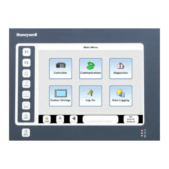
Introduction Overview What’s in this guide This guide contains instructions on assembly, installation, wiring, and operation of the 900 Control Station, shown in Figure 1. Figure 1 900 Control Station menu Revision 9 900 Control Station User Guide May 14... -
Page 14: Typical Readers Of This Guide
Display various process data such as trends, alarms, diagnostics, setpoint profiles, and control loops. • Store process data to disk. Specifications Refer to 900 Control Station Specifications document #51-52-03-46. CE Conformity (Europe) This product is in conformity with the protection requirements of the following European Council Directives: , the Low Voltage Directive, and , the EMC Directive. -
Page 15: Components
• Alarm processing • Store data logs principal function blocks such as • PID control, Advanced control, loops and SPPs. Configure data autotuning, fuzzy logic logs for storage and trend viewing. Revision 9 900 Control Station User Guide May 2014... -
Page 16: Preparation And Startup
See document 51-52-05-01, How to Apply Digital Instrumentation in Severe Electrical Noise Environments. How to configure your Control Station The Control Station is shipped from the factory unconfigured. Use Honeywell’s Station Designer application to configure your Control Station. The overall steps for configuration are as follows. -
Page 17: Startup
After connecting the Controller and Control Station and downloading your .sds file to the Control Station, the Home display appears with 16 buttons. (Actual button text may vary.) Figure 2 Home display Revision 9 900 Control Station User Guide May 2014... - Page 18 Preparation and startup Startup This page has been intentionally left blank. 900 Control Station User Guide Revision 9 May 2014...
-
Page 19: Features
For data storage and booting up from an image file. See page 11 Status LEDs Status of power, CompactFlash and alarms. See page 12 Ports Connections for data storage and communications. See page 13 Revision 9 900 Control Station User Guide May 14... -
Page 20: Touch Screen
Status bar Always visible. Shows status of: See page 10. • Logs • Diagnostics • Alarms • Events • Controller • Language 900 Control Station User Guide Revision 9 May 2014... -
Page 21: Navigation And Data Entry
Grayed out text, field or button. Not accessible or Example: Loop output not adjustable in Auto applicable under current conditions. mode. Example: Redundant Overview button is not active for non-redundant HC900s. Revision 9 900 Control Station User Guide May 2014... -
Page 22: Status Bar
Controller mode, time and date. Touch to go to Controller Setup. See page 19. Language of displayed text is indicated by flag icon. Touch to go to Language Setup. See page 68 900 Control Station User Guide Revision 9 May 2014... -
Page 23: Keys
CompactFlash socket is on the left side. Use CompactFlash card for: • storing data logs (.csv) • storing print screen images (.bmp) • loading image file (.sdi). NOTE: Maximum Compact Flash memeory size is 2GB, minimum Compact Flash size is 4MB. Revision 9 900 Control Station User Guide May 2014... -
Page 24: Status Leds
PC connected via the USB port has locked the drive. Flashing slowly Incorrectly formatted CompactFlash card present. Red LED Indication Flashing A tag is in alarm state. Steady Valid configuration is loaded and no alarms are present. 900 Control Station User Guide Revision 9 May 2014... -
Page 25: Ports
Features Ports Ports 900 Control Station 10 inch model 900 Control Station 15 inch model Revision 9 900 Control Station User Guide May 2014... -
Page 26: Usb Device
HC900. Port A PGM Port may be connected to your PC. NOTE: The 15" model has two Ethernet ports and two RS485 ports whereas the 10" model has one of each. 900 Control Station User Guide Revision 9 May 2014... -
Page 27: Main Menu
File management of CompactFlash and USB device. Adjust/calibrate/clean touch screen. View status of communication ports. Set passwords. Log On Security manager for logging on. Data Logging File management of Data Logs. Revision 9 900 Control Station User Guide May 14... -
Page 28: Main Menu Tree
Export Data to USB Download Controller Memory Device Utilities Configuration Upload Controller Configuration Download Recipes Upload Recipes Download Security Upload Security Export Data Logs Export Data to USB Upload Database Image Format Memory Device 900 Control Station User Guide Revision 9 May 2014... -
Page 29: Controller
Controller Type 900C30, 900C50, 900C70 and 900C75 Controller Name Configured controller name Local Alias A locally referenced alias for the controller. Control Firmware Revision level of the Controller software. Revision Level Revision 9 900 Control Station User Guide May 2014... - Page 30 Maximum time used to complete the digital control cycle (Sec) Fast Logic CB Number of times that the processing of the digital control blocks exceeds the Overruns allocated digital cycle time 900 Control Station User Guide Revision 9 May 2014...
-
Page 31: Controller Setup
• In a cold start, all data storage and display buffers are cleared and accumulated values of some function blocks (such as totalizers) are reset. • In a resume, all buffered data and values are retained and the process resumes where it left off. Revision 9 900 Control Station User Guide May 2014... -
Page 32: Summary Displays
The following additional fields are displayed when an I/O Safety Function Block Analog Output Validated is configured. 7. VFAIL 8. FBFAIL The Analog Variable Summary Display shows the following fields: Variable Number Description 900 Control Station User Guide Revision 9 May 2014... - Page 33 7. FBFAIL The Digital Output Summary Display shows the same information as above plus the Type of the module. The Digital Variable Summary Display shows following fields: Variable Number Description Data Revision 9 900 Control Station User Guide May 2014...
-
Page 34: Communications
Modbus slave devices. The three Modbus Slave protocols allow the controller to act as a slave to various host devices, including a PC running HC Designer. The information presented in Table 6 and Table 9 also applies to Serial Port S1 when a Redundant Controller is used. 900 Control Station User Guide Revision 9 May 2014... -
Page 35: Table 6 Serial Port S1/S2 Statistics (Left Side Of Display)
This item resets the message counters for this port back to zero (Messages Clear Statistics Received, Data Link Errors, and Application Errors). Note: the counters will only be reset if the controller is in Run Mode. Revision 9 900 Control Station User Guide May 2014... -
Page 36: Table 7 Serial Port S1/S2: Port Diagnostic Status
4. If configured as Modbus Master port, associated slave blocks have their read pin values frozen to the last value read. HARDWARE The DUART is failing Replace the controller CPU module. FAILURE to operate properly. 900 Control Station User Guide Revision 9 May 2014... -
Page 37: Table 8 Serial Port S1/S2 Settings (Right Side Of Display)
Little Endian format Byte order: 1, 2, 3, 4 FP BB Big Endian with byte-swap Byte order: 3, 4, 1, 2 FP LB Little Endian with byte-swap Byte order: 2, 1, 4, 3 Revision 9 900 Control Station User Guide May 2014... -
Page 38: Table 9 Protocol Selection Versus Setup Parameters For The Serial Port S1/S2
Slave Port Enable Double Register Format Note: When “Modbus Slave Modem” protocol is selected, the Modbus Parity and Modbus Stop Bits are fixed at “None” and “1 Bit” respectively and cannot be changed. 900 Control Station User Guide Revision 9 May 2014... -
Page 39: Ethernet Port E1/E2 Status
FP BB Floating Point Big Endian with byte-swapped Byte order – 3, 4, 1, 2 FP L Floating Point Little Endian Format Byte order – 1, 2, 3, 4 FP LB Floating Point Little Endian with byte-swapped Byte order – 2, 1, 4, 3 Revision 9 900 Control Station User Guide May 2014... -
Page 40: Table 11 Ethernet Port E1/E2: Port Diagnostic Status
Replace CPU module. FAILURE failed during power-up. DHCP Failure DHCP is configured, Same as above Check the DHCP server. and no IP address has Download a configuration with been granted. DHCP required. 900 Control Station User Guide Revision 9 May 2014... -
Page 41: Expansion Rack Communications
Number of message attempts to the rack that resulted in failed response. Total Count Total for all racks. Clear Statistics Reset the messages and link error counters for all racks to zero. Revision 9 900 Control Station User Guide May 2014... -
Page 42: Table 13 Expansion Rack Communication Status
RACK OK pin is turned off. 4. SYSTEM MONITOR block’s HW OK pin is turned off. 5. The statuses for the AO, AI, DI, DO channels that are affected are set to BAD_CHANNEL. 900 Control Station User Guide Revision 9 May 2014... -
Page 43: Modbus Slave Devices
(b) accessing a register that is not supported by the slave device, or (c) using a Modbus function code that is not supported by the slave device. YES : Scanning has been enabled Scan Enabled NO : Scanning has been disabled Revision 9 900 Control Station User Guide May 2014... -
Page 44: Host Connections
DIAG is set to WARNING. Rack 1 monitor block's RACK OK pin is turned off. ASYS block's HW OK pin is turned off 900 Control Station User Guide Revision 9 May 2014... -
Page 45: Peer Connections
IP address range per the configured IP mask, • share the same peer network name. Clear Statistics Reset to zero the number of messages received and application errors. Revision 9 900 Control Station User Guide May 2014... -
Page 46: Table 18 Peer Connection Status
3. Check that all external network components such as switches and routers allow passing of UDP packets on port 502. 4. Check that the peer device is powered on and is in RUN mode. 900 Control Station User Guide Revision 9 May 2014... -
Page 47: Troubleshooting A Comm Quality Problem
17. Verify that all devices on the link have the correct baud rate and parity settings. 18. Verify that all terminating resistors are installed properly. Verify that the ohm-value of the terminating resistors is correct. 19. Verify controller is set to unterminated for RS-485 communications. Revision 9 900 Control Station User Guide May 2014... -
Page 48: Diagnostics
Motor Setup (p. 172) Communication Diagnostics Controller Communications This links to the main Communications menu. See page Redundant Overview (p. 48) Lead CPU Diagnostics (p. 56) Reserve CPU Diagnostics (p. 56) 900 Control Station User Guide Revision 9 May 2014... -
Page 49: Controller Diagnostics
Master Advanced protocol for either the at least one Modbus slave devices. RS-232 or RS-485 port. slave block, but neither the RS-232 nor the RS-485 port is set up as a Modbus Master port. Revision 9 900 Control Station User Guide May 2014... - Page 50 Flash failed to burn 1. Force a cold start. block’s RACK OK pin is 2. Replace CPU board. turned off. 2. SYSTEM MONITOR block’s HW OK pin is turned off. I/O Status GOOD 900 Control Station User Guide Revision 9 May 2014...
- Page 51 7. Cycle power to the rack. 8. Cycle power to the hub. 9. Replace the expansion rack’s power supply. 10. Replace the expansion rack. 11. Replace the expansion rack’s scanner board. 12. Replace the main CPU. Revision 9 900 Control Station User Guide May 2014...
- Page 52 RTC failed to program See NOT See BAD DATA. FAILURE PROGRAMMED. READ FAILURE Unable to read RTC See NOT See BAD DATA. PROGRAMMED. Comm Port Good Status (Rack IO Comm Link Status (Rack 2-5) 900 Control Station User Guide Revision 9 May 2014...
- Page 53 I/O on CPUA and I/O B is connected to I/O on CPUB and CPUB are the I/O on the associated connected to the rack wrong ports on the I/O scanner CPU Revision 9 900 Control Station User Guide May 2014...
-
Page 54: I/O Module Diagnostics And I/O Calibration
DO 24 VDC 32-CHAN PULSE/FREQ/QUAD 4-CHAN HIGH LEVEL AO 8 CHANNEL HIGH LEVEL AO 16 CHANNEL Analog Input, Analog Output, Digital Input, Digital Output, Pulse Frequency CONFIGURED AS Quadrature See Table 22. ERROR STATUS 900 Control Station User Guide Revision 9 May 2014... -
Page 55: Table 21 I/O Module Details
PULSE/FREQ/QUAD 4-CHAN HIGH LEVEL AO 8 CHANNEL HIGH LEVEL AO 16 CHANNEL PART NUMBER The re-order part number of the module. FIRMWARE REV. Revision level of the firmware running on this module. Revision 9 900 Control Station User Guide May 2014... -
Page 56: Table 22 I/O Module Error Status
3. Associated rack monitor block’s module fail pin is turned on. 4. Associated rack monitor block’s RACK OK pin is turned off. 5. SYSTEM MONITOR block’s HW OK pin is turned off. 900 Control Station User Guide Revision 9 May 2014... - Page 57 3. Associated rack monitor block’s module fail pin is turned on. 4. Associated rack monitor block’s RACK OK pin is turned off. 5. SYSTEM MONITOR block’s HW OK pin is turned off. Revision 9 900 Control Station User Guide May 2014...
-
Page 58: Table 23 Bad Module Details
(AI=convertor not working) √ √ √ √ √ HW/SW Key The software residing on the Replace module module does not match the module type. This diagnostic should only result in the factory. 900 Control Station User Guide Revision 9 May 2014... -
Page 59: Table 24 Bad Channel Details
A Digital Output module detected an excessive amount of current on its output terminals. Note that this message will only appear for the 32- channel DO module. A BAD CHANNEL module diagnostic is posted. Revision 9 900 Control Station User Guide May 2014... -
Page 60: Communication Diagnostics
RSM Module has failed Replace RSM RSM SWITCH IS Switch is indicating an The controller will Replace RSM invalid position continue to operate with a bad RSM. Automatic failover is still possible if required. 900 Control Station User Guide Revision 9 May 2014... - Page 61 Modbus Master Advanced least on Modbus slave Modbus slave protocol for either the RS-232 or block, but Serial Port S1 devices. RS-485 port. is not set up as a Modbus Master port. Revision 9 900 Control Station User Guide May 2014...
- Page 62 ERROR ON E1 NETWORK PORT REFER TO Table 11 (page 28) ERROR ON E2 NETWORK PORT REFER TO Table 11 (page 28) ERROR ON SCANNER I/O LINK REFER TO Table 26 (page 51) 900 Control Station User Guide Revision 9 May 2014...
-
Page 63: Table 26 Details Of Rack Diagnostics Error Status Messages
1. Associated rack Replace battery. monitor block’s RACK OK pin is turned off. 2. SYSTEM MONITOR block’s LOW BATTERY pin is turned on. 3. SYSTEM MONITOR block’s HW OK pin is turned off. Revision 9 900 Control Station User Guide May 2014... - Page 64 If not powered (un- Restore rack operation powered outputs) Loss of AC mains Restore AC mains power, reset breaker Bad Power Supply Replace Power Supply Failed Scanner2 Replace Scanner2 900 Control Station User Guide Revision 9 May 2014...
- Page 65 Apply power to reserve CPU but failover is not possible. CPU rack backplane Replace CPU rack backplane failure Contact Honeywell Service. Revision 9 900 Control Station User Guide May 2014...
- Page 66 I/O 2. Check connectors of all on the associated cables. rack 3. If a hub/switch is being used, verify that it is one that is recommended by Honeywell 4. Replace cables. 900 Control Station User Guide Revision 9 May 2014...
- Page 67 I/O on CPUA and connected to the wrong to access the I/O on I/O B is connected to I/O on ports on the I/O the associated rack CPUB scanner CPU Revision 9 900 Control Station User Guide May 2014...
-
Page 68: Lead/Reserve Cpu Diagnostics
Lead or Reserve. The CPU Position parameter on each display identifies which physical CPU module is currently acting as the Lead or Reserve. Refer to Table 27 through for a description of the information contained on these displays. 900 Control Station User Guide Revision 9 May 2014... -
Page 69: Table 27 Details Of Lead Or Reserve Cpu Diagnostics Error Status Messages
(lead and reserve CPUs have different firmware revisions Database not Replace the reserve CPU. If this synchronized with doesn’t help, replace the lead the lead CPU. If this doesn’t help, replace the backplane. Revision 9 900 Control Station User Guide May 2014... - Page 70 Estimated battery life is 1. Associated rack Replace battery. WARNING less than 5 days. monitor block’s RACK OK pin is turned off. 2. SYSTEM MONITOR block’s HW OK pin is turned off. 900 Control Station User Guide Revision 9 May 2014...
- Page 71 4. Replace boards in rack. 5. Replace rack. See NOT PROGRAMMIN RTC failed to program See BAD DATA. PROGRAMMED. G FAILURE See NOT READ FAILURE Unable to read RTC See BAD DATA. PROGRAMMED. Revision 9 900 Control Station User Guide May 2014...
- Page 72 REFER TO Table 11 Ethernet Port E1/E2: Port Diagnostic status page 28 PORT E2 SERIAL PORT REFER TO Table 7 Serial Port S1/S2: Port Diagnostic status page 24 SERIAL PORT REFER TO Table 7 Serial Port S1/S2: Port Diagnostic status page 24 900 Control Station User Guide Revision 9 May 2014...
-
Page 73: Station Settings
File/ folders can’t be copied from USB memory device to CompactFlash’s LOG folder. There may be a delayed response in actions involving the USB memory device since it is an external device. Revision 9 900 Control Station User Guide May 2014... -
Page 74: Format Memory Device
Lets you change the language on the Control Station UI. Use one of the following methods to change the language. • Go to Station Setup Menu > Languages. • Click the flag icon present on the screen. 900 Control Station User Guide Revision 9 May 2014... -
Page 75: Log On
Log On Select the required language. Log On Enter name and password. Once logged on, your level of access to displays and functions depends on the security credentials you were configured for. Revision 9 900 Control Station User Guide May 2014... -
Page 76: Alarms And Events
Display Details • Alarm Console - 900 Control Station shows both the HC900 Controller alarms and Station alarms on the same alarm console. • Alarms programmed to automatically acknowledge when the alarm clears may also be manually acknowledged while the alarm is active, halting the flashing indications on the alarm displays. -
Page 77: Alarm Groups
The Alarm Groups screen shows the status of the alarm groups of the controller. Touch an Alarm Group button to open its Alarm Group display. There is a button at the bottom of the Alarm Groups screen to access Station alarms. Revision 9 900 Control Station User Guide May 2014... -
Page 78: Alarm Group Indication
Unacknowledged and continue to flash until acknowledged. Alarm Group Overview The Alarm Group screen shows the status of each point present in the selected Alarm Group. 900 Control Station User Guide Revision 9 May 2014... -
Page 79: Alarm Point Indication
When 900CS is connected to C30S, C50S, C70S and C75S Controllers then it will not be allowed to Acknowledge Alarms in Safety portion of the configuration when controller is in RUN-LOCKED mode, it is allowed when controller is RUN-program mode. Revision 9 900 Control Station User Guide May 2014... -
Page 80: Event Access
Event Definition • 900 Control Station shows both the HC900 Controller events and Station events on the same Alarm and Event Summary console. • Station events can be configured for a .cde file tag present in the .sds configuration. An event can be defined in the Alarms tab of the desired tag properties. -
Page 81: Data Logging
Lets you view the alarm and event logs. Touch the + and – buttons to scroll through the folder and file names. Touch Open button to open a folder or file. Touch Back to go back to the top level folder. Revision 9 900 Control Station User Guide May 2014... -
Page 82: View Data Logs
Touch the Show Data Logs button to view the data logs and touch the Show Batch Logs button to view the batch logs. 900 Control Station User Guide Revision 9 May 2014... -
Page 83: Export Data Logs To Usb
(Concurrent Batch for Control Station) The operator at the 900 Control Station can simply touch the LOGS button on the master slide to access the Data Logging menu. (Alternately, you can touch the soft key Menu > Data Logging.) The Data Logging menu has two buttons on it for concurrent batch. - Page 84 This is Data Logger property Retain Header in Station Designer under the Data Logger’s Groups tab, so the field values shown are not empty. 900 Control Station User Guide Revision 9 May 2014...
- Page 85 If you specify a very long value, note that it can overflow its data box. Just touch on a data box to the right of a field name to specify its value. Touch the Confirm Header button when you are satisfied with your entries: Revision 9 900 Control Station User Guide May 2014...
-
Page 86: Delete Data Logs
Delete Data Logs Lets you view one or all data log files on CompactFlash. Use the + and – buttons to navigate through the folder and files. 900 Control Station User Guide Revision 9 May 2014... -
Page 87: Downloading And Uploading Controller Configuration
Press Open to open the file/folder and to show its contents. Press Back to close the opened file/folder. Press Close to close the dialog box. Select a file and press Download. The Download Controller Configuration dialog box appears. Revision 9 900 Control Station User Guide May 2014... - Page 88 Select one of the following options as required and continue. • Hot Start: Updated the configuration settings. • Cold Start: To re-initialize the memory. • Stay in Program Mode: Remains in program mode. • Abort: To cancel the download operation. 900 Control Station User Guide Revision 9 May 2014...
-
Page 89: Upload Controller Configuration
Press Open to open a folder and to show its contents. Press Open to select a file. Press Back to close the opened file/folder. Press Close to close the dialog box. Revision 9 900 Control Station User Guide May 2014... - Page 90 Select a file and press Upload. The Upload Controller Configuration dialog box appears. Press Start Upload to start the process. A progress bar indicates the percentage of completion. Once the upload is complete, the Controller Upload Complete dialog box appears. 900 Control Station User Guide Revision 9 May 2014...
-
Page 91: Uploading Database Image
Control Station. Loading From CF message appears on the screen. To upload an image .sdi file from a memory stick appropriate settings must be enabled via Station Designer, the PC configuration tool. (see manual 51-52-25-149). Revision 9 900 Control Station User Guide May 2014... -
Page 92: Uploading And Downloading Recipe Files
Uploading and Downloading Recipe Files Using the 900 Control Station you can upload the recipe files from a controller to a USB memory device. You can also download the recipe files present in the USB Memory device or Compact Flash card onto the controller. - Page 93 On successful file download, File Downloaded Successfully message is displayed. In case the download fails, an error message is displayed. Similar method is used for downloading different types of recipe file. Revision 9 900 Control Station User Guide May 2014...
-
Page 94: Upload Recipe Files
Upload Sequence Recipe File, or Upload Schedule Recipe File. Select a location to save the file. File can be saved in C: or D: drive. By default file is saved as Upload1. However, you can overwrite the file name. 900 Control Station User Guide Revision 9 May 2014... - Page 95 On successful file upload, File Uploaded Successfully message is displayed. In case the upload fails, an error message is displayed. Similar method is used for uploading different types of recipe file. Revision 9 900 Control Station User Guide May 2014...
-
Page 96: Uploading And Downloading Security Settings
‘.dat’ extension is added to the file name. Press Upload to upload the file to the database. The following message appears indicating the successful upload of security file. In case the upload fails, the following message is displayed. 900 Control Station User Guide Revision 9 May 2014... - Page 97 Uploading and Downloading Security Settings By default, Security is used as the file name. If you over write the file name, you are prompted with the following message. Press Yes or No as required. Revision 9 900 Control Station User Guide May 2014...
-
Page 98: Download Security Displays And Functionality
If carriage return and line feed are not included in the scan, the user touches the Enter button on the keypad, the pop-up goes away, and the data appears in the data box. 900 Control Station User Guide Revision 9... -
Page 99: Process Displays
For example, a loop PID widget lets you not only view and adjust the loop’s SP and output, but also lets you jump to detailed displays for the loop (such as loop setup, trending, tuning, alarm setpoints, and output limiting). Revision 9 900 Control Station User Guide May 14... - Page 100 AGA8DL & AGA8GS 4-Selector Switch Device Control Hand/Off/Auto Switch Stage Ramp Alternator Calendar Event Wireless transmitters Setpoint Programmers Setpoint Schedulers Sequencers Loops (A/M Bias, Carbon, On/Off, PID, 3 Position Step Control) 900 Control Station User Guide Revision 9 May 2014...
-
Page 101: How To Edit A Parameter
Menu scroll through available choices. Buttons common to all popups: Cancel change or exit without saving changes. Save changes. Tab to other writable fields on the display. Revision 9 900 Control Station User Guide May 2014... -
Page 102: Pushbuttons, Signals And Variables
Read-only shows value of analog signal. No actions. Digital Signal Read-only shows state of a digital signal. No actions. Analog Variable Touch value to edit. Digital Variable Touch state to edit. 900 Control Station User Guide Revision 9 May 2014... -
Page 103: Aga8Dl & Aga8Gs
Gross Method 2 calculates the super-compressibility and gas density from knowledge of the relative density, Nitrogen, carbon dioxide, hydrogen and carbon monoxide components. Revision 9 900 Control Station User Guide May 2014... -
Page 104: Table 28 Aga Parameters
INVALID TERM IN VIRGS AGA 8 - GROSS Error FLOWING PRESSURE (PF) <= 0.0 PR > 1740.0 PSIA AGA 8 - GROSS Error FLOWING TEMPERATURE (TF) < 14.0 OR > 149.0 DEG F 900 Control Station User Guide Revision 9 May 2014... - Page 105 SUM OF MOLE FRACTIONS < 0.98 OR > 1.020 AGA 8 - DETAIL Warning FLOWING PRESSURE (PF) < 0.0 OR > 1750. PSIA AGA 8 - DETAIL Warning FLOWING TEMPERATURE (TF) < 17 OR > 143 DEG F Revision 9 900 Control Station User Guide May 2014...
- Page 106 AGA 3 - ORIFICE Warning BETA RATIO (DO/DM) WAS < 0.1 OR > 0.75 GENERAL Block is disabled – process value outputs are set to 0 and OPERATION error/warning pins are turned off. 900 Control Station User Guide Revision 9 May 2014...
-
Page 107: Aga Detail Gas Components
Apply New Local Values Select to transfer the New Local Values to the Local Values. These values do not take effect unless Active Gas Component Values is set to Local Values, above. Revision 9 900 Control Station User Guide May 2014... -
Page 108: Aga8 Gross Setup
Calorimeter reference temperature in units selected by the UNITS configuration parameter. Calorimeter Ref Pres Calorimeter reference pressure in units selected by the UNITS configuration parameter. Combustion Ref Temp Combustion reference temperature in units selected by the UNITS configuration parameter. continued 900 Control Station User Guide Revision 9 May 2014... -
Page 109: 4-Selector Switch
To operate, press the desired state button for each function. When pressed, the buttons turn yellow to indicate the selected state. Revision 9 900 Control Station User Guide May 2014... -
Page 110: Device Control
Reset Select to reset the control when it is in the FAILED state to return it to the READY state. 900 Control Station User Guide Revision 9 May 2014... -
Page 111: Device Control Setup
Touch the blue title bar to access the setup display. Item Description START DELAY Current start delay time in seconds STOP DELAY Current stop delay time in seconds FEEDBACK FAIL DELAY Current feedback fail delay time in seconds Revision 9 900 Control Station User Guide May 2014... -
Page 112: Hand/Off/Auto Switch
The rotary dial and yellow button indicate the selected state (Hand, Off, Auto. Use buttons to change state. If the current state is BYPASS, any requests to change the state are ignored. 900 Control Station User Guide Revision 9 May 2014... -
Page 113: Stage
Output (request). Output Output of the stage. Off, On, or Disabled. Override Override On input pins and Override Off input pins of the function block. None, On, or Off. Revision 9 900 Control Station User Guide May 2014... -
Page 114: Stage Setup Display
ON. Interlock with Next Stage Set to YES to prevent a stage’s output from turning OFF until the output of the next stage in sequence has turned OFF. 900 Control Station User Guide Revision 9 May 2014... -
Page 115: Ramp
PV input pin of function block OUTPUT Output pin of function block STATUS Enable (YES) or Disable (NO) of the ramp. OVERRIDE OFF, LOW, or HIGH – Override status of each ramp input pin. Revision 9 900 Control Station User Guide May 2014... -
Page 116: Ramp Setup Display
Input high limit value applied to the PV after signal lag. Range: Full scale +/– within PV range limits. IN LOW LIMIT Input low limit value applied to the PV after signal lag. Range: Full scale +/– within PV range limits. 900 Control Station User Guide Revision 9 May 2014... -
Page 117: Alternator
Delay time used before turning ON the next output in the sequence. Range: 0-99999 seconds Off Delay (Sec) Delay time used before turning OFF the next output in the sequence. Range: 0-99999 seconds Revision 9 900 Control Station User Guide May 2014... -
Page 118: Alternator Setup Display
BREAK – (Break before Make) The output is removed before advancing the sequence and activating the next output. MAKE/BREAK is READ ONLY. Max Out Maximum number of outputs used. 900 Control Station User Guide Revision 9 May 2014... - Page 119 Input Status On or Off. Output Status Blank – Normal operating output (no designation) On or Off. Revision 9 900 Control Station User Guide May 2014...
- Page 120 This could be handled by changing the sequence. • Taking a pump out of service for maintenance. After editing, save the output sequence. 900 Control Station User Guide Revision 9 May 2014...
-
Page 121: Calendar Event
The value of the Feedback Signal for Events 1 through 8. The assignment of a Feedback feedback signal is optional. If no feedback signal is assigned this column of the display will be blank. Revision 9 900 Control Station User Guide May 2014... -
Page 122: Calendar Event Block Menu
Select this to edit one of the 16 Special Days. Select this item to see how the Events will behave when a Special Day View Special Days Event Setup occurs (see page 112). 900 Control Station User Guide Revision 9 May 2014... -
Page 123: Edit Event Setpoints
Note: If either the MONTH or the DAY has a value of OFF, the Special Day is disabled. Both the MONTH and the DAY must be set to a legal value to activate a Special Day. Revision 9 900 Control Station User Guide May 2014... -
Page 124: View Special Days Event Setup
The behavior of the Event output is not overridden on Special Days. The Event output will trigger the way it normally triggers, based on the configuration of the currently active Setpoint Group. 900 Control Station User Guide Revision 9 May 2014... -
Page 125: Wireless Transmitters
Last read value of base radio. Offline or Online. Transmitters expected Number of Expected Transmitters communicating to the base station. Transmitters communicating Number of Transmitters actually communicating with the base radio. Revision 9 900 Control Station User Guide May 2014... -
Page 126: Xyr5000 Transmitter
Switch Input #2 On or Off Touch the blue title bar to open the XYR5000 Transmitter Setup display. This shows the Square root of primary Differential Transmitter output status: On or Off. 900 Control Station User Guide Revision 9 May 2014... -
Page 127: Xyr6000 Transmitter
Firmware: Error or Good • Watchdog Timer: Error or Good Radio status Error or Good PV1, PV2, PV3, PV4 Value of each Process Variable Input Status Error or Good Output Status Error or Good Revision 9 900 Control Station User Guide May 2014... - Page 128 This page is intentionally left blank. 900 Control Station User Guide Revision 9 May 2014...
-
Page 129: Variable Recipes
See Figure 8. NOTE: The contents of the variable recipe cannot be edited from the recipe selection widget. For editing, the recipe must be uploaded, modified, then downloaded to the controller. Revision 9 900 Control Station User Guide May 2014... -
Page 130: Figure 8 Variable Recipe Selection Display
The value of this variable may then be added to the Variable Recipe Load display to receive verification that the desired recipe operation has been executed in the controller. See Figure 8 900 Control Station User Guide Revision 9... -
Page 131: Setpoint Programmers
Also, function block inputs will override inputs from the Control Station, which occur during the same execution cycle. Finally, state changes from the Control Station are processed on the basis of the “last change wins.” Revision 9 900 Control Station User Guide May 2014... -
Page 132: Setpoint Programmer Overview Widgets
GHOLD: Profile is paused because of excessive deviation. STOP: Profile has reached the end of the last segment. DISABLE: Profile is prevented from starting until the programmer disable control is ON. 900 Control Station User Guide Revision 9 May 2014... - Page 133 Touch to put program in HOLD. Reset Touch to reset a HOLD or STOP program to the first segment. Any edits made to the program are lost unless they were SAVED. See SAVE on the display. Revision 9 900 Control Station User Guide May 2014...
-
Page 134: Setpoint Programmer - Pre Plot Display
Status of the Setpoint Programmer Events (1-16) • Current Primary SP value • Current Primary PV value • Primary PV Engineering Units • Current Auxiliary SP Value • Current Auxiliary PV Value 900 Control Station User Guide Revision 9 May 2014... -
Page 135: Setpoint Programmer Pre-Plot Graph Attributes
The number of user programmed segments in the profile (The user may use from 2 to 50 of the available segments for his program.) b) The time units specified for the profile (minutes or hours) Revision 9 900 Control Station User Guide May 2014... -
Page 136: Process Variable Trend Plot Attributes
The Jog-to segment can cause the program to go to a higher or lower segment number from its current segment. Following a Jog-to event, the Process Variable plot starts plotting from the beginning of the Jog-to segment. 900 Control Station User Guide Revision 9 May 2014... -
Page 137: Auxiliary Sp And Pv Pre-Plot
It shows the details of the profile currently running in the Setpoint Programmer. You can also load a different profile from memory into the Setpoint Programmer, edit the current profile, and save the edited profile to any slot (profile number) in memory. Revision 9 900 Control Station User Guide May 2014... - Page 138 Jump to the next segment. When the program is already in the last segment, the advance request is ignored. Programs cannot be advanced to the first segment. Current state must either READY or HOLD. 900 Control Station User Guide Revision 9 May 2014...
- Page 139 Save To Profile Number.) When the profile is RESET, any edits are lost unless they are first saved with Save To Profile Number. See View/Edit profile on page 129. Revision 9 900 Control Station User Guide May 2014...
-
Page 140: Figure 9 Recipe Load
Select Save To Profile Number 2. Select a position to save recipe to. 3. Touch Save Profile. 4. Current recipe with edits is saved to Controller memory Figure 10 Recipe Save 900 Control Station User Guide Revision 9 May 2014... -
Page 141: View/Edit Profile
The profile will hold if a PV deviates more than this amount above the profile setpoint. Guaranteed Hold Low Limit The profile will hold if a PV deviates more than this amount below the profile setpoint. Revision 9 900 Control Station User Guide May 2014... - Page 142 When FAST FORWARD is ON, the program will run at a speed 60 times faster. When FAST FORWARD is OFF, the program will run at normal speed. 900 Control Station User Guide Revision 9 May 2014...
-
Page 143: View/Edit Profile Segments
Starting Value Starting value of the segment. Time/Rate Range = 0.00 hr. to 999.99 hr. or 0.00 min. to 999.99 min. The function of this value depends on the Ramp Type. Revision 9 900 Control Station User Guide May 2014... -
Page 144: Edit Events
Events turn ON as soon as the previous segment is completed even if the process variable has not reached the soak setpoint. Events can be edited only while program is in READY state. 900 Control Station User Guide Revision 9 May 2014... -
Page 145: Setpoint Scheduler
Also, function block inputs will override inputs from the Control Station, which occur during the same execution cycle. Finally, state changes from the Control Station are processed on the basis of the “last change wins.” Revision 9 900 Control Station User Guide May 2014... -
Page 146: Setpoint Scheduler Operate
GHOLD: Schedule is paused because of excessive deviation. STOP: Schedule has reached the end of the last segment. DISABLE: Schedule is prevented from starting until the Scheduler disable control is ON. Segment Information Segment number Current segment 900 Control Station User Guide Revision 9 May 2014... - Page 147 Reset a HOLD or STOP schedule to the first segment. Any edits made to the schedule are lost unless they were saved. See Save To Schedule List. PVs and SPs SP1 through SP8 Value of all setpoints PV1 through PV8 Value of all PVs. Revision 9 900 Control Station User Guide May 2014...
- Page 148 When the schedule is RESET, any edits are lost. To save your edits, see Save To Schedule List. See View/Edit schedule on page 137. 900 Control Station User Guide Revision 9 May 2014...
-
Page 149: View/Edit Schedule
GHOLD state (all setpoints, auxiliary setpoints, and segment events freeze on their current value or state) until none of the limits are exceeded, whereupon the schedule will resume RUN state. Revision 9 900 Control Station User Guide May 2014... -
Page 150: View/Edit Schedule Segments
The last segment must be a soak. Edit Auxiliary Setpoints This display lets you edit the 8 auxiliary setpoint values for each segment. All values are as of the beginning of the segment. 900 Control Station User Guide Revision 9 May 2014... -
Page 151: Edit Time & Recycles
ON/OFF outputs. When a segment event is turned ON, it remains ON until the end of the segment at which time it is turned OFF unless it is configured to turn ON in the next segment. Events can be edited only while schedule is in READY state. Revision 9 900 Control Station User Guide May 2014... - Page 152 Setpoint Scheduler View/Edit Schedule Segments This page is intentionally left blank. 900 Control Station User Guide Revision 9 May 2014...
-
Page 153: Sequencers
Sequencer function block, a Sequence can be modified through the menus provided on this Control Station. A modified Sequence can also be saved back to the pool for later recall, if desired. Revision 9 900 Control Station User Guide May 2014... -
Page 154: Sequencer Operate
READY: Sequence is at the beginning of step and is ready to run. Mode HOLD: Sequence is paused at the setpoint value shown. RUN: Sequence is executing normally. STOP: Sequence has reached the end of the last step. 900 Control Station User Guide Revision 9 May 2014... - Page 155 When the sequence is RESET, any edits are lost unless you saved them first with Save To Sequence Number. See View/Edit Sequence on page 144. Revision 9 900 Control Station User Guide May 2014...
-
Page 156: View/Edit Sequence
Description of the sequence. Jog to Step When the sequencer’s JOG input is triggered, the sequencer will jump to the start of this step then continue. Time Units Hours or minutes. 900 Control Station User Guide Revision 9 May 2014... -
Page 157: View/Edit Sequence Steps
When Event Signal 2 is triggered the sequence will jump to Event 2 Next Step. Event 2 Next Step When Event Signal 2 is triggered the sequence will jump to Event 2 Next Step. Revision 9 900 Control Station User Guide May 2014... -
Page 158: Edit Auxiliary
When manually advanced the sequence will jump to this step. Aux Output Value of auxiliary analog output View Outputs 1-8/9-16 These buttons take you to displays that show the state of each step’s 16 outputs. Read only. 900 Control Station User Guide Revision 9 May 2014... -
Page 159: Loops
(remote set point).You can change the SP, Bias and Output values/states when LSP and Manual modes are selected. Touch the blue title bar at the top of the widget to jump to the Loop Setup display for more details. Revision 9 900 Control Station User Guide May 2014... -
Page 160: Loop Setup
3 POS CARBON A/M BIAS Control Setup (p. 150) Loop Tuning (p. 151) Tuning Constants (p. 155 Alarm Setpoints (p. 156) High Output Limiting (p. 157) X indicates button is accessible 900 Control Station User Guide Revision 9 May 2014... -
Page 161: Loop Modes
When PID Secondary is in Manual or when Local Setpoint is selected, PID Primary mode is IMAN. IMAN causes the PID Primary output to track the PID Secondary PV. Figure 11 IMAN loop mode Revision 9 900 Control Station User Guide May 2014... -
Page 162: Loop Control Setup
(IN) from the oxygen probe, temperature of the probe, and %H. The equations used are probe-type dependent and are supplied by the manufacturer. 900 Control Station User Guide Revision 9 May 2014... -
Page 163: Loop Tuning
There is no change to the PID algorithm, and the fuzzy logic does not alter the PID tuning parameters. This Item can be independently Enabled or Disabled as required by the application to work with “TUNE” On-Demand tuning. Revision 9 900 Control Station User Guide May 2014... - Page 164 FAST - More aggressive tuning than Normal. Designed to calculate under damped parameter values providing faster control to the setpoint but may have some overshoot. 900 Control Station User Guide Revision 9 May 2014...
- Page 165 PV ADT RUNNING - PV tuning is active monitoring the process. ABORT - Current Accutune III process was aborted. An active Accutune III process will be aborted is if the loop is placed in the Manual mode. Revision 9 900 Control Station User Guide May 2014...
- Page 166 Select a value between 0.10 and 10.0. Normal value is 1. This value is used to estimate the size of the initial output step for a Setpoint Tune. Start Tune Select this to begin the Accutune III process. 900 Control Station User Guide Revision 9 May 2014...
-
Page 167: Tuning Constants
PV up to setpoint. * Either Gain or Proportional Band is displayed but not both. ** Visible for PID and Carbon loop types only. Revision 9 900 Control Station User Guide May 2014... -
Page 168: Alarm Setpoints
To generate the alarm, AL1 and AL2 pins of loops should be connected to the Signal Tags in HC Designer. These signal tags can be configured to generate alarms in Station Designer. 900 Control Station User Guide Revision 9 May 2014... -
Page 169: High Output Limiting
Rate of zero causes override limit to track the loop’s tracking value during the delay time, after which high output limit steps without ramping to the normal output high limit. Revision 9 900 Control Station User Guide May 2014... - Page 170 Loops Loop Setup This page is intentionally left blank. 900 Control Station User Guide Revision 9 May 2014...
-
Page 171: I/O Calibration
PPO Motor Calibration (p. Error! Overview Bookmark not defined. ) Calibration Status Information Cancel Calibration Calibration Errors Auto Calibration Procedure Semi-Auto Calibration Procedure Hand Calibration Procedure Motor Setup (p. Error! Bookmark not defined. ) Revision 9 900 Control Station User Guide May 2014... -
Page 172: Overview
I/O Calibration Overview Overview This display lets you select the type of calibration. You must change the controller mode before calibrating. 900 Control Station User Guide Revision 9 May 2014... -
Page 173: Ai Calibration
This will allow you to calibrate out any inaccuracies in the shunt resistor. A high-precision shunt resistor should always be used. Revision 9 900 Control Station User Guide May 2014... -
Page 174: Calibrate Ai Channel
Restore Factory Calibration. Status will show “Restore AI Input”, then green “Done” or red “Restore AI Failed.” After calibration, return the Controller to Run mode. Use IO Calibration display (page 159) or Controller Mode button (page 10). 900 Control Station User Guide Revision 9 May 2014... -
Page 175: Cj Calibration
Restore Factory Calibration. Status will show “Restore CJ Input”, then green “Done” or red “Restore CJ Failed.” After calibration, return the Controller to Run mode. Use IO Calibration display (page 159) or Controller Mode button (page 10). Revision 9 900 Control Station User Guide May 2014... -
Page 176: Ao Calibration
Select this to calibrate. Status will indicate when calibration is complete. Save Select this to save the channel calibration. After calibration, return the Controller to Run mode. Use IO Calibration display (page 159) or Controller Mode button (page 10) 900 Control Station User Guide Revision 9 May 2014... -
Page 177: Cancel Calibration
AO channel to be restored, then press Restore Factory Calibration. Status will show “Restore AO Input”, then green “Done” or red “Restore AO Failed.” After calibration, return the Controller to Run mode. Use IO Calibration display (page 159) or Controller Mode button (page 10). Revision 9 900 Control Station User Guide May 2014... -
Page 178: Ppo Motor Calibration
Feedback Value– this field shows the motor feedback value [a value between 0.0 and 1.0]. This value should change whenever the motor is actually moving. Calibration Block– Select the PPO to be calibrated. 900 Control Station User Guide Revision 9 May 2014... -
Page 179: Cancel Calibration
Calibration Failed – Wrong AI The firmware on the AI module Obtain a new AI module from Version your supplier. does not support PPO motor control using a slide wire for the position feedback. Revision 9 900 Control Station User Guide May 2014... -
Page 180: Auto Calibration Procedure
• Status – Calibration Completed. Once calibration is completed, select one of the following choices from the Motor Position popup: Position Motor at 0%, Position Motor at 100, Don’t Move Motor. 900 Control Station User Guide Revision 9 May 2014... -
Page 181: Semi-Auto Calibration Procedure
Feedback Value – indicates movement and direction of the motor [0.0 to 1.0] Percent Complete – indicates the progress of this step [0 to 100%] • Status – Motor Speed Calibration Complete Revision 9 900 Control Station User Guide May 2014... -
Page 182: Hand Calibration Procedure
Percent Complete – will remain at 0% during this step. Move the motor by hand to the 100% position. When complete, go to step 5. 900 Control Station User Guide Revision 9 May 2014... - Page 183 Status – Wait…Saving Calibration Values. Feedback Value – indicates the current position of the motor [0.0 to 1.0] Percent Complete – indicates the progress of this step [0 to 100%] • Status – Calibration Completed Revision 9 900 Control Station User Guide May 2014...
-
Page 184: Motor Setup
Travel time is the time it takes the motor to travel from its calibrated 0% position to its calibrated 100% position. Output Low Limit Low limit for the motor position. Output High Limit High limit for the motor position. 900 Control Station User Guide Revision 9 May 2014... -
Page 185: Maintenance
IP Address is 192.168.1.253 with TCP/IP download enabled on port 789. MAC Address is… Hold 1st and 4th keys on power-up to configure IP” Re-load the Control Station configuration. See Station Designer manual 51-52-25-149 for details on Downloading to a device. Revision 9 900 Control Station User Guide May 2014... -
Page 186: What To Do If You Want To Change The Ip Address At The Control Station
MAC Address is… Hold 1st and 4th keys on power-up to configure IP” Using the new IP Address, download a Station Designer database file to the 900 Control Station by means of the Link menu. 900 Control Station User Guide... -
Page 187: How To Remove The Rear Cover And Change The Battery Of The Operator Interface
* Please note that the old battery must be disposed of in a manner that complies with your local waste regulations. Also, the battery must not be disposed of in fire, or in a manner whereby it may be damaged and its contents come into contact with human skin. Revision 9 900 Control Station User Guide May 2014... -
Page 188: Parts
EXPLOSION HAZARD Substitution of components may impair suitability for Class I, Division 2. Replace parts with appropriate Honeywell parts only. Failure to do so may result in explosion causing death or serious injury. To order parts below, see the contact information in the front of this manual. -
Page 189: Index
................16 Diagnostics ..............10 Maintenance ..............173 Redundant Overview ..........48 mode controller modes defined ..........19 Mounting ................ 4 Events ................10 Setpoint schedule ......See Setpoint schedule parts Revision 9 900 Control Station User Guide May 2014... - Page 190 ..........120, 126, 134, 142 Setpoint schedule clear from scheduler......... 110, 111 defined ..............133 Warm Start edit ................137 defined ..............19 edit guarantee hold ........... 139 edit segment events ..........139 900 Control Station User Guide Revision 9 May 2014...
- Page 191 Revision 9 900 Control Station User Guide May 2014...
-
Page 192: Sales And Service
Honeywell Korea Co Ltd Phone: +(822) 799 6114 Fax: +(822) 792 9015 Specifications are subject to change without notice. For more information To learn more about HC 900 Process Controller, visit www.honeywellprocess.com Or contact your Honeywell Account Manager Process Solutions...