Table of Contents
- 1 Table of Contents
- 2 Description
- 3 Features
- 4 Dimensional Drawing S4965 Boiler Control
- 5 Specifications
- 6 Connection Diagram
- 7 Timing Diagram
- 8 Description of LOCON
- 9 Description of SQUARE
- 10 General Considerations
- 11 Electrical Connections and Wiring
- 12 Adjustments and Final Checkout
- 13 EMC Guidelines
- 14 Quality Assurance Statement
- 15 Standards and Approvals
- 16 Ordering Information
COMBINED VALVE AND BOILER CONTROL SYSTEMS
S4965 SERIES
APPLICATION
The S4965 boiler controls have been developed for application
in gas fired domestic appliances.
The S4965 boiler controls are used in conjuction with the
VK41.. series modulating or non modulating gas controls. (see
Product Handbook EN2R-9025 and EN2R-9004) They provide
both an optimised safety sub-system for programmed safe
light-up and flame supervision of the main burner of the
appliance and a boiler comfort control sub system for
temperature, pump, and 3-way valve control
Bi-directional communication with a MMI enables
comprehensive diagnostics and operation.
For glossary of terms, abbrevations and symbols see
document EN2R-9039
General
Description ......................................................................... 2
Features ............................................................................ 3
Dimensional drawing S4965 boiler control ........................ 4
Technical
Specifications .................................................................... 5
Connection diagram .......................................................... 7
Timing diagram ................................................................ 8
Description of LOCON ...................................................... 9
Description of SQUARE ................................................... 10
General considerations ................................................... 11
Electrical connections and wiring .................................... 12
Adjustments and final checkout ...................................... 13
Various
EMC guidelines ............................................................... 14
Quality assurance statement ........................................... 15
Standards and approvals ................................................ 15
Ordering information ....................................................... 16
1
PRODUCT HANDBOOK
Contents
EN2R-9053 0408R11-NE
Table of Contents

Related Manuals for Honeywell S4965 Series


Summary of Contents for Honeywell S4965 Series
-
Page 1: Table Of Contents
S4965 SERIES COMBINED VALVE AND BOILER CONTROL SYSTEMS PRODUCT HANDBOOK APPLICATION The S4965 boiler controls have been developed for application in gas fired domestic appliances. The S4965 boiler controls are used in conjuction with the VK41.. series modulating or non modulating gas controls. (see... -
Page 2: Description
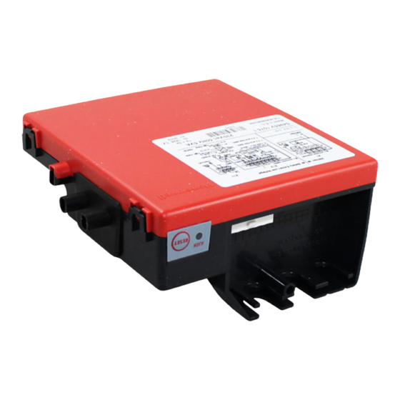
DESCRIPTION The Combined Valve Boiler Control (CVBC) is the combination of a VK41.. modulating or non-modulating gas control with an electronic boiler control. The boiler control consists of an automatic ignition control and a comfort boiler control. Most of the standard control functions of a gas fired boiler can be performed within one single control box which can easily be clicked on the gas control. -
Page 3: Features
FEATURES • Multi trial full sequence ignition control. • Permanent operation in accordance with EN 298 (2003). • Non volatile lock-out. • Self learning ignition sequence; no minimum adjustment, using LOCON. • Direct Burner- or Intermittent Pilot operation. • Integral ignition including emission filter. •... -
Page 4: Dimensional Drawing S4965 Boiler Control
DIMENSIONAL DRAWING S4965 BOILER CONTROL Material : ABS - V0 Tolerances ± 1 mm unless noted Molex Minifit (for X1) and Microfit (for X11 and X12) can be FOR CONNECTORS, USE FEMALE PARTS used as alternatives Plastic part Pins Terminal TYCO 1-106527-0 TYCO 106528-2 (reel) (for AWG 22-26, insulation... -
Page 5: Specifications
SPECIFICATIONS Models Basically there is one PCB for a number of applications. Depending on which components are mounted different applications can be covered. Atmospheric combustion Premix combustion SQUARE Normal Combustion feedback Normal Application (LoCon) (Pneumatic (Electronic gas/air gas/air) or Gas addaptive) Open flue Fan assistant Open flue... - Page 6 Communication Bit rate: 2400 baud Byte format: 1 start, 8 data, 1 stop, no parity Bit value “1“: low line level at connector Bit value “0“: high line level at connector RS232 with additional PC cable (nr. 45.900.419-038). (see document EN2R-9066) Cable and wiring length flame sensing cable and spark cable 0.5 m max.
-
Page 7: Connection Diagram
CONNECTION DIAGRAM COM / GND COM / GND in / out in / out in / out in / out in / out in / out in / out in / out Vdc (output) in / out in / out in / out in / out in / N... -
Page 8: Timing Diagram
TIMING DIAGRAM DBI + IP pilot main valve Alarm stab post purge pre purge pre ignition pre purge pre ignition Fig. 5. General timing diagram CVBC EN2R-9053 0408R11-NE... -
Page 9: Description Of Locon
(P0) ign flame (P0) max Boilerload Fig. 7. Ionisation flame current versus the boiler load REMARK: Electrode postition and choice is important. In cooperation with Polidoro, Honeywell has made a standard solution. New applications require Honeywell approval. EN2R-9053 0408R11-NE... -
Page 10: Description Of Square
DESCRIPTION OF SQUARE TECHNOLOGY SQUARE is the abbreviation of Self adaptive, Quality, User SQUARE is based on the phenomena that the ionisation friendly, Adjustment free, Reliable, Environmental friendly. current is a measure of the gas quality at a specific range of the burner load in a fully premix burner. -
Page 11: General Considerations
WARNING check time of about 10 seconds. NOTE 2.: Electrical rating of connected controls should be Honeywell is not responsible for damage and/or injury appropriate for the load that is switched by the due to mis wiring. boiler control. After installation boiler control can become wet due to NOTE 3.:... -
Page 12: Electrical Connections And Wiring
ELECTRICAL CONNECTIONS AND WIRING WARNING Take care that installer is a trained experienced service person. Disconnect power supply to prevent electrical shock and/or equipment damage. IMPORTANT Wiring must be in accordance with local regulations. The appliance manufacturer’s instructions should always be followed when provided. If such instructions are not provided see the connection diagrams for typical systems. -
Page 13: Adjustments And Final Checkout
ADJUSTMENTS AND FINAL CHECKOUT Final checkout WARNING After installation and any adjustment start the appliance and observe a complete cycle to ensure that all burner Adjustments must be made by qualified persons only. components function correctly. If the appliance manufacturer supplies checkout and/ or service and maintenance instructions carefully follow Maintenance and service them. -
Page 14: Emc Guidelines
EMC GUIDELINES The position of the ignition cable has to be determined for low- est emission. Do not lead ignition cable close to other cabling. To suppress Radio Frequency Interference (RFI) the boiler control including spark ignition cable should be mounted in sufficient shielded environment. -
Page 15: Quality Assurance Statement
Quality System. maintaining, improving and verification of the quality systems in the field of design, production process and field quality The quality system is described in the Honeywell Combustion service. Controls Center Quality Assurance Programme and its related operational procedures and instructions. -
Page 16: Ordering Information
An up-to-date product survey, with details of all required. new and existing products in these series, is available. Contact your local Honeywell sales • Cover should be ordered seperately : representative for more information. order nr: 45.900.431-014 (the same screw can be used)