Bosch DCN Next Generation Installation & User's Instructions
Digital congress network
Hide thumbs
Also See for DCN Next Generation:
- Installation and operation manual (286 pages) ,
- Operation manual (290 pages) ,
- Installation and user instructions manual (158 pages)

Related Manuals for Bosch DCN Next Generation


Summary of Contents for Bosch DCN Next Generation
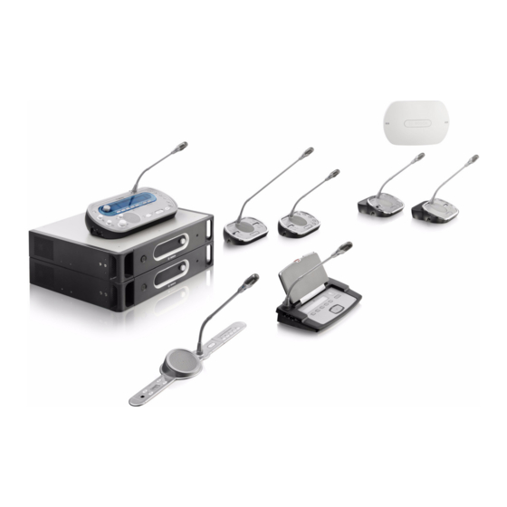
- Page 1 DCN Next Generation Installation and User Instructions Digital Congress Network...
-
Page 3: Important Safeguards
DCN Next Generation | Installation and User Instructions | Important Safeguards en | 3 Important Safeguards Before you install or operate the DCN Next Generation digital congress network, you must read the Important Safety Instructions. The Important Safety Instructions are supplied together with the central control unit. -
Page 4: Disclaimers
DCN Next Generation | Installation and User Instructions | Disclaimers en | 4 Disclaimers CobraNet is a trademark of Peak Audio — a division of Cirrus Logic, Inc. — in the United States and/or other countries. Bosch Security Systems | 2007-02 | 9922 141 70525... -
Page 5: About This Manual
DCN Next Generation | Installation and User Instructions | About this manual en | 5 About this manual Signs The Installation and User Instructions shows each precaution with a sign. The sign shows the effect if you Function do not obey the instruction. - Page 6 DCN Next Generation | Installation and User Instructions | About this manual en | 6 Electro-static discharges Conversion tables Electro-static discharges can damage electric Length, mass and temperature are in SI units. Refer to components. You must take measures to prevent the data below to change SI units to imperial units.
-
Page 7: Table Of Contents
DCN Next Generation | Installation and User Instructions | Table of Contents en | 7 Table of Contents Important Safeguards ..............................3 Disclaimers ..................................4 About this manual .................................5 Table of Contents ................................7 Section 1 - System Design and Planning......................13 1. DCN design ....................................14 Introduction .................................... - Page 8 DCN Next Generation | Installation and User Instructions | Table of Contents en | 8 Introduction .................................... 40 Controls, connectors and indicators ..........................41 Internal settings ..................................42 Installation ....................................46 External connections ................................46 Downloading ..................................51 Initialization ..................................... 51 Configuration ..................................
- Page 9 DCN Next Generation | Installation and User Instructions | Table of Contents en | 9 13.4 External connections .................................122 13.5 Configuration menu ................................124 13.6 CobraNet Discovery ................................129 13.7 CNConfig .....................................131 Section 3 - Contribution Devices.......................... 135 14. DCN-DIS Discussion Units ..............................136 14.1 Introduction ..................................136...
- Page 10 DCN Next Generation | Installation and User Instructions | Table of Contents en | 10 22.2 Controls, connectors and indicators ..........................178 22.3 Internal settings ..................................178 22.4 Installation ....................................178 22.5 External connections .................................179 23. DCN-FMICB Microphone Control Panel ..........................180 23.1 Introduction ..................................180 23.2 Control, connectors and indicators ..........................180...
- Page 11 DCN Next Generation | Installation and User Instructions | Table of Contents en | 11 33.2 Controls, connectors and indicators ..........................204 33.3 Installation ....................................207 33.4 External connections .................................208 33.5 Operation .....................................210 33.6 Configuration ..................................213 33.7 Operation .....................................217 Section 6 - Installation Devices ..........................219 34.
- Page 12 DCN Next Generation | Installation and User Instructions | Table of Contents en | 12 43.5 Technical data ..................................239 44. LBB4417/00 Optical Network Connectors ........................240 45. LBB4418/00 Cable-connector Tool Kit ..........................241 45.1 Introduction ..................................241 45.2 Contents ....................................241 45.3 Connector components ..............................243 45.4 Assemble the Cable-connector ............................244...
-
Page 13: Section 1 - System Design And Planning
DCN Next Generation | Installation and User Instructions | System Design and Planning en | 13 Section 1 - System Design and Planning Bosch Security Systems | 2007-02 | 9922 141 70525... -
Page 14: Dcn Design
DCN Next Generation | Installation and User Instructions | System Design and Planning en | 14 DCN design Limit 2: Power capacity • The maximum power that one DCN socket of the central control unit can supply is 65 W. -
Page 15: Control Capacity
DCN Next Generation | Installation and User Instructions | System Design and Planning en | 15 Control capacity Power capacity 1.5.1 Active devices 1.6.1 Introduction Active devices are devices that can: Each device uses power, and most devices do not have •... - Page 16 DCN Next Generation | Installation and User Instructions | System Design and Planning en | 16 1.6.3 Power supplies 1.6.3.3 DCN-CCUB 1.6.3. 1 Introduction The devices that supply power to the DCN are the DCN-CCUB central control unit and the extension power supply C aution R is k of electric s hock.
-
Page 17: Cable Lengths
DCN Next Generation | Installation and User Instructions | System Design and Planning en | 17 1.6.4 Overload indication 1.7.3 Between regenerative tap-offs Each DCN socket of the central control unit and The total cable length between two regenerative tap-off extension power supply has a red LED that comes on to sockets must not be more than 100 m. - Page 18 DCN Next Generation | Installation and User Instructions | System Design and Planning en | 18 1.7.5.3 Total power consumption 1.7.5.5 Graph Do as follows: The power correction graph (refer to figure 1.4) corrects 1 Find the power consumption of each device from the the power level to compensate for the extension cables.
-
Page 19: Examples
DCN Next Generation | Installation and User Instructions | System Design and Planning en | 19 Examples All examples use the power correction graph (refer to figure 1.4). 1.8.1 Discussion devices DCN-CCUB C aution R is k of electric s hock. - Page 20 DCN Next Generation | Installation and User Instructions | System Design and Planning en | 20 1.8.2 Conference devices DCN-CCU RS 232 Port 1 Mains Audio In 1 Audio Out 1 Audio In 2 Audio Out 2 RS 232 Port 2...
- Page 21 DCN Next Generation | Installation and User Instructions | System Design and Planning en | 21 1.8.3 DCN-CCU(B) power correction table 1.5: DCN-CCU(B) power correction examples Type Extension Diagram Power for Corrected cable devices power DCN- 63.3 W 23 x 2.75 63.25 W...
-
Page 22: Interpretation Devices
DCN Next Generation | Installation and User Instructions | System Design and Planning en | 22 Interpretation devices With an LBB4115/00 Protected Trunk Splitter, you can The maximum number of interpreter desks you can connect two interpreter desks (refer to figure 1.8). If an install in an interpreter booth is six. -
Page 23: Optical Network Design
DCN Next Generation | Installation and User Instructions | System Design and Planning en | 23 Optical network design Control capacity Each device in the optical network has a number of nodes (refer to table 2.1). The maximum number of 2. -
Page 24: Cabling
DCN Next Generation | Installation and User Instructions | System Design and Planning en | 24 2.5.3 Power supply 2.5.3.3 DCN-NCO If a network controller is connected, it will supply power 2.5.3. 1 Introduction to the optical network. In this case, the DCN-CCUs The devices that supply power to the optical network then only supply power to the DCN sockets. - Page 25 DCN Next Generation | Installation and User Instructions | System Design and Planning en | 25 2.6.2 Optical fiber length 2.6.4 Maximum cable length Because of optical attenuation, the maximum length of The maximum cable length (LBB4416 and GOF) of the optical network cables (LBB4416) is 50 m.
-
Page 26: Example Layouts
DCN Next Generation | Installation and User Instructions | System Design and Planning en | 26 Example layouts 2.6.5 Bending The minimum bend radius of a 90 degree bend in an 2.7.1 Introduction LBB4416 cable is 110 mm (refer to figure 2.3). A 180 degree bend is the same as two 90 degree bends. - Page 27 DCN Next Generation | Installation and User Instructions | System Design and Planning en | 27 2.7.3 Redundant optical network 2.7.4 Tap-offs The basic optical network (refer to figure 2.5) has no The network splitter (LBB4410/00) lets you make redundant cables. If the cable between the central tap-offs (refer to figure 2.7).
- Page 28 DCN Next Generation | Installation and User Instructions | System Design and Planning en | 28 2.7.5 Multi-CCU system Refer to figure 2.8 for an example of a basic multi-CCU system. The following can be connected to a multi-CCU system: •...
-
Page 29: Wireless Language Distribution
DCN Next Generation | Installation and User Instructions | System Design and Planning en | 29 Wireless language distribution You can connect the system to an Integrus digital infra-red language distribution system. This system has a transmitter, radiators and receivers. -
Page 30: Cobranet
DCN Next Generation | Installation and User Instructions | System Design and Planning en | 30 CobraNet CobraNet is a standard for the transport of real-time digital audio and control data through an Ethernet network. A CobraNet network can transport a maximum of 64 channels of 48 kHz, 20-bit audio through a 100 Mbit link connection in each direction. -
Page 31: User Set-Up
DCN Next Generation | Installation and User Instructions | System Design and Planning en | 31 User set-up Speaking distance The recommend speaking distance from the microphones is 0.2 m to 0.4 m. 5. 1 Public areas Interpreter booths 5.1.1... -
Page 32: Device Set-Up
DCN Next Generation | Installation and User Instructions | System Design and Planning en | 32 Device set-up Ventilation Keep a good airflow. Airflow holes are in the front, right and left sides of all 19-inch devices (for example, the 6. -
Page 33: Acoustic Feedback
DCN Next Generation | Installation and User Instructions | System Design and Planning en | 33 Acoustic feedback Acoustic feedback (‘howling’) occurs when the sound of the loudspeakers or headphones in the system is sent to the system again by enabled microphones. -
Page 34: Technical Data
DCN Next Generation | Installation and User Instructions | System Design and Planning en | 34 Technical data 7. 1 System electrical and electro-acoustic characteristics 7.1.1 General table 7. 1 : Electro-acoustic characteristics Nominal input level: 85 dB SPL Overload input level:... -
Page 35: Environmental Conditions
DCN Next Generation | Installation and User Instructions | System Design and Planning en | 35 7.1.3 Combined devices from input to • Interpreter microphone with transmission link to output interpreter headphones • Delegate microphone with transmission link to •... -
Page 36: Electro-Magnetic Compatibility
DCN Next Generation | Installation and User Instructions | System Design and Planning en | 36 Electro-magnetic compatibility table 7.5: Electromagnetic compatibility EMC compatibility: According ECM Directive 89/336/EEC amended by Directive 93/68/ECC European approvals: CE marking EMC environment: for commercial or professional use EMC emission: According harmonized standard EN 55103-1 (E3) (prof. - Page 37 DCN Next Generation | Installation and User Instructions | System Design and Planning en | 37 Bosch Security Systems | 2007-02 | 9922 141 70525...
- Page 38 DCN Next Generation | Installation and User Instructions | System Design and Planning en | 38 Bosch Security Systems | 2007-02 | 9922 141 70525...
-
Page 39: Section 2 - Central Devices
DCN Next Generation | Installation and User Instructions | Central Devices en | 39 Section 2 - Central Devices Bosch Security Systems | 2007-02 | 9922 141 70525... -
Page 40: Dcn-Ccu Central Control Unit
DCN Next Generation | Installation and User Instructions | Central Devices en | 40 DCN-CCU Central Control Unit 8. 1 Introduction The DCN-CCU Central Control Unit controls the system. The central control unit can operate with or without a control PC. -
Page 41: Controls, Connectors And Indicators
DCN Next Generation | Installation and User Instructions | Central Devices en | 41 Controls, connectors and indicators 8.2.1 Front view The front of the central control unit (refer to figure 8.1) contains: 1 On/off switch - Starts and stops the central control unit. -
Page 42: Internal Settings
DCN Next Generation | Installation and User Instructions | Central Devices en | 42 Internal settings 8.2.2 Rear view The rear of the central control unit (refer to figure 8.1) 8.3.1 Overview contains: 5 RS232 ports - Connect a PC, remote controllers or... - Page 43 DCN Next Generation | Installation and User Instructions | Central Devices en | 43 17 16 S600 B601 S601 B602 B604 X605 X600 X103 G600 B1000 F100 X1001 X1000 S800 S1000 S500 X155 X104 figure 8.2: Internal settings Bosch Security Systems | 2007-02 | 9922 141 70525...
- Page 44 DCN Next Generation | Installation and User Instructions | Central Devices en | 44 8.3.2 S600 switches table 8. 1 : S600 switches (* = default) Switch Position Description S600-1 Reserved. Do not change the position of this switch. S600-2 Reserved.
- Page 45 DCN Next Generation | Installation and User Instructions | Central Devices en | 45 8.3.4 Internal back-up battery 8.3.5 Watchdog Use the X600 jumper block to connect and disconnect Use the X605 jumper to enable or disable the watchdog the internal back-up battery of the central control unit of the central control unit (refer to table 8.5).
-
Page 46: Installation
DCN Next Generation | Installation and User Instructions | Central Devices en | 46 Installation External connections Install the central control unit in a 19-inch rack system 8.5.1 Power supply or on a flat surface. Four feet and two brackets are... - Page 47 DCN Next Generation | Installation and User Instructions | Central Devices en | 47 8.5.3 Optical network 4 Connect the power cable to a power supply. Connect the trunk of the optical network to the optical network sockets of the central control unit with optical network cables (refer to figure 8.6).
- Page 48 DCN Next Generation | Installation and User Instructions | Central Devices en | 48 8.5.4 Headphones 8.5.5 Audio inputs You can connect headphones to the headphones socket You can connect an external analog audio source to the of the central control unit. The headphones must have a audio inputs of the central control unit.
- Page 49 DCN Next Generation | Installation and User Instructions | Central Devices en | 49 8.5.6 Audio outputs You can select the procedure that is used to send audio signals through the central control unit with the audio You can connect an audio recording device or a public routing modes (refer to section 8.10.11).
- Page 50 DCN Next Generation | Installation and User Instructions | Central Devices en | 50 8.5.7 Fault contact You can select the procedure that is used to send audio signals through the central control unit with the Use the fault contact to send the condition of the central available audio routing modes (refer to section 8.10.11).
-
Page 51: Downloading
DCN Next Generation | Installation and User Instructions | Central Devices en | 51 Downloading 8.5.8 RS232 ports You can connect a PC, remote controllers or video To download the software do the following: cameras to the RS232 ports of the central control unit 1 Install the download and license tool on a PC (the (refer to chapter 8.9). -
Page 52: Configuration
DCN Next Generation | Installation and User Instructions | Central Devices en | 52 8.7.3 Devices You can also do the initialization of active devices that are added to the system after you did the initialization of the system. 3 Set the value of the parameter in the menu item to Yes. - Page 53 DCN Next Generation | Installation and User Instructions | Central Devices en | 53 8.8. 1 .2 Open In the Open mode, delegates can enable their microphones with the microphone button on their Note Microphones of chairman units can always be contribution devices.
- Page 54 DCN Next Generation | Installation and User Instructions | Central Devices en | 54 4< 4< DCN-SW DCN-SW Legend Legend Contribution devices Contribution devices DCN-CCU DCN-CCU Interpretation devices Interpretation devices Optical network Optical network Chime Chime figure 8. 1 2: Recorder figure 8.
- Page 55 DCN Next Generation | Installation and User Instructions | Central Devices en | 55 When you connect to a telephone coupler: • Go to menu item 7G Routing I/O 2 to set the systems to the Mix minus mode. •...
- Page 56 DCN Next Generation | Installation and User Instructions | Central Devices en | 56 8.8.6 Intercom 8.8.2.6 Local floor Local floor is used to create directional sound. In the 8.8.6. 1 Introduction Local floor mode, audio output 4 of the central control...
-
Page 57: Camera Control Configuration
DCN Next Generation | Installation and User Instructions | Central Devices en | 57 • LBB4162 Stand-alone Camera Control software module for systems without a PC. 8.9.2.3 Installation 1 Connect a video display to the video output of the Camera control configuration AutoDome video camera. - Page 58 DCN Next Generation | Installation and User Instructions | Central Devices en | 58 alone Camera Control software module (refer to the • Video displays (refer to the DCN Next Generation User Manual of the LBB4162 stand-alone Camera Data Brochure for recommended video displays).
- Page 59 DCN Next Generation | Installation and User Instructions | Central Devices en | 59 9 pole D-type 9 pole D-type Note (female) (male) When you make the cable that figure 8.22 shows, mark the ends of the cable with ‘CCU’...
- Page 60 DCN Next Generation | Installation and User Instructions | Central Devices en | 60 2 Connect the LTC5136 AutoDome Controller to the AutoDome video camera. 9 pole D-type Terminal 3 Set the pre-positions of the AutoDome video camera (male) with the AutoDome controller.
- Page 61 DCN Next Generation | Installation and User Instructions | Central Devices en | 61 • Video cameras (refer to the DCN Next Generation Data Brochure for recommended video cameras). 9 pole D-type 9 pole D-type • Allegiant video switcher with keyboard (refer to the...
-
Page 62: Configuration Menu
DCN Next Generation | Installation and User Instructions | Central Devices en | 62 8. 1 0 Configuration menu 8.10.1 Overview Use the configuration menu of the central control unit to configure the central control unit and the system (refer to figure 8.29). - Page 63 DCN Next Generation | Installation and User Instructions | Central Devices en | 63 8.10.2 Navigation and operation 8. 1 0.2.6 To open the main menu To open the main menu, push the knob in the Main 8. 1 0.2. 1 Menu items The configuration menu consists of menu items.
- Page 64 DCN Next Generation | Installation and User Instructions | Central Devices en | 64 8. 1 0.2. 1 1 To select a parameter 8. 1 0.2. 1 6 Example 1 Open the correct menu item (refer to section For an example, do as follows to change the level of 8.10.2.10).
- Page 65 DCN Next Generation | Installation and User Instructions | Central Devices en | 65 6 Push the knob to open the sub-menu item. 12 Push the knob to go back to the main menu. 7 Turn the knob to move the cursor to the value that is 13 Turn the knob clockwise to go to the <...
- Page 66 DCN Next Generation | Installation and User Instructions | Central Devices en | 66 8. 1 0.3.2 Multi mode The following screen is displayed. Note If you do not turn or push the knob for three minutes, the display automatically goes back to the Main menu item.
- Page 67 DCN Next Generation | Installation and User Instructions | Central Devices en | 67 8.10.5 Microphone mode Use the 1 Microphone mode menu item to set the microphone mode (refer to table 8.24). table 8.24: Microphone mode sub-menu (* = default)
- Page 68 DCN Next Generation | Installation and User Instructions | Central Devices en | 68 8.10.7 Treble Use the 3 Treble menu to set the level of the treble of the loudspeakers of the contribution devices (refer to table 8.27). table 8.27: Treble sub-menu (* = default)
- Page 69 DCN Next Generation | Installation and User Instructions | Central Devices en | 69 8.10.10 Enquiry Use the 6 Enquiry menu item to open the Enquiry sub-menu. The menu items in this sub-menu give general data about the central control unit (refer to table 8.30).
- Page 70 DCN Next Generation | Installation and User Instructions | Central Devices en | 70 table 8.31: Setup sub-menu (* = default) Menu item Parameter Value Description 7A Mic. Priority Temporarily off* The action taken by the system when the Permanently off chairman releases the priority button (refer to section 8.8.4).
- Page 71 DCN Next Generation | Installation and User Instructions | Central Devices en | 71 8.10.12 Intercom Use the menu items in the 7E Intercom sub-menu to identify the location of the chairman and the operator (refer to table 8.32 and section 8.8.6).
-
Page 72: Dcn-Ccub Basic Central Control Unit
DCN Next Generation | Installation and User Instructions | Central Devices en | 72 DCN-CCUB Basic Central Controls, connectors and indicators Control Unit 9.2.1 Front view The front of the basic central control unit (refer to figure 9. 1 Introduction 9.1) contains:... -
Page 73: Internal Settings
DCN Next Generation | Installation and User Instructions | Central Devices en | 73 Installation 9.2.2 Rear view The rear of the basic central control unit (refer to figure This information is the same for the basic central control 9.1) contains: unit and the CCU (refer to section 8.4). - Page 74 DCN Next Generation | Installation and User Instructions | Central Devices en | 74 9.5.4 Audio inputs You can connect an external analog audio source to the table 9.2: Audio input details, line level signals audio inputs of the basic central control unit. The basic Number of connections: central control unit has two audio inputs.
-
Page 75: Downloading
DCN Next Generation | Installation and User Instructions | Central Devices en | 75 Downloading This information is the same for the basic central control table 9.3: Audio output, connection Type Signal Description unit and the CCU (refer to section 8.6). -
Page 76: Dcn-Nco Network Controller
DCN Next Generation | Installation and User Instructions | Central Devices en | 76 DCN-NCO Network Controller 10. 1 Introduction The DCN-NCO network controller controls a multi DCN-CCU system. The network controller can operate with or without a control PC. -
Page 77: Controls, Connectors And Indicators
DCN Next Generation | Installation and User Instructions | Central Devices en | 77 10.2 Controls, connectors and indicators 10.2.1 Front view The front of the network controller (see figure 10.1) contains: 1 Loudspeaker - for monitoring purposes. The loudspeaker is muted when headphones are connected to the headphones socket (4). -
Page 78: Internal Settings
DCN Next Generation | Installation and User Instructions | Central Devices en | 78 10.2.2 Rear view 17 Power inlet - Connects the network controller to the mains power supply with a power cable (refer to The rear of the network controller (refer to figure 10.1) section 10.6.1). - Page 79 DCN Next Generation | Installation and User Instructions | Central Devices en | 79 figure 10.2: Internal view of the network controller 10.3.2 Ground Note When you connect the system ground to the Use the ground jumper block to connect and disconnect...
-
Page 80: Downloading
DCN Next Generation | Installation and User Instructions | Central Devices en | 80 10.4 Downloading 10.5 Installation To download the software do the following: Refer to section 8.4 for information about the 1 Install the download and license tool on a PC (the installation of the network controller. - Page 81 DCN Next Generation | Installation and User Instructions | Central Devices en | 81 10.6.2 Connecting back-up power 10.6.4 Headphones Connect the back-up supply to the back-up power Refer to section 8.5.4 for information about the connector on the back of the network controller. Refer headphones socket of the network controller.
- Page 82 DCN Next Generation | Installation and User Instructions | Central Devices en | 82 10.6.6 Audio outputs You can select the procedure that is used to send audio signals through the network controller with the audio You can connect an audio recording device or a public routing modes (refer to section 10.10.11).
- Page 83 DCN Next Generation | Installation and User Instructions | Central Devices en | 83 10.6.7 Fault contact You can select the procedure that is used to send audio signals through the network controller with the available The network controller has 5 control outputs (see figure audio routing modes (refer to section 10.10.11).
- Page 84 DCN Next Generation | Installation and User Instructions | Central Devices en | 84 10.6.8 Ethernet connection 10.6.9 RS232 ports The network controller has a RS232 port for connecting 10.6.8. 1 Introduction dome camera and video switchers (refer to section 10.9).
-
Page 85: Initialization
DCN Next Generation | Installation and User Instructions | Central Devices en | 85 10.7 Initialization Initialize a multi CCU system as follows: 1 Initialize each CCU and all of its devices (refer to section 8.7). 4< 2 For each CCU, select a unique multi CCU slave, and change the mode from "single"... - Page 86 DCN Next Generation | Installation and User Instructions | Central Devices en | 86 10.8.2.3 Insertion 10.8.2.4 Mix-minus In the Insertion mode, audio output 4 and audio input 4 Use the Mix-minus mode to: of the network controller are used to add signals from •...
-
Page 87: Camera Control Configuration
DCN Next Generation | Installation and User Instructions | Central Devices en | 87 10.8.3 Attention chimes This information is the same for the network controller and the CCU (refer to section 8.8.3). 10.8.4 Erase requests-to-speak and 4< speakers This information is the same for the network controller and the CCU (refer to section 8.8.4). - Page 88 DCN Next Generation | Installation and User Instructions | Central Devices en | 88 10.9.2 Direct camera control without a This information is the same for the network controller and the CCU (refer to section 8.9.2), except that: • the protocol for RS 232 on the network controller is permanently set to camera control.
-
Page 89: Configuration Menu
DCN Next Generation | Installation and User Instructions | Central Devices en | 89 10. 1 0 Configuration menu 10.10.1 Overview Use the configuration menu of the network controller to configure the network controller and the system (refer to figure 10.12). - Page 90 DCN Next Generation | Installation and User Instructions | Central Devices en | 90 10.10.2 Navigation and operation 10.10.4 Pop-up message This information is the same for the network controller When the network controller detects a fault, the display and the CCU (refer to section 8.10.2) shows a pop-up message.
- Page 91 DCN Next Generation | Installation and User Instructions | Central Devices en | 91 10.10.5 Microphone mode Use the 1 Microphone mode menu item to set the microphone mode (refer to table 10.13). table 10. 1 3: Microphone mode sub-menu (* = default)
- Page 92 DCN Next Generation | Installation and User Instructions | Central Devices en | 92 10.10.7 Treble Use the 3 Treble menu to set the level of the treble of the loudspeakers of the contribution devices (refer to table 10.16). table 10. 1 6: Treble sub-menu (* = default)
- Page 93 DCN Next Generation | Installation and User Instructions | Central Devices en | 93 10.10.10Enquiry Use the 6 Enquiry menu item to open the Enquiry sub-menu. The menu items in this sub-menu give general data about the network controller (refer to table 10.19).
- Page 94 DCN Next Generation | Installation and User Instructions | Central Devices en | 94 table 10.20: Setup sub-menu (* = default) Menu item Parameter Value Description 7A Mic. Priority Temporarily off* The action taken by the system when the Permanently off chairman releases the priority button (refer to section 8.8.4).
- Page 95 DCN Next Generation | Installation and User Instructions | Central Devices en | 95 10.10.12Intercom Use the menu items in the 7E Intercom sub-menu to identify the location of the chairman and the operator (refer to table 10.21 and section 8.8.6).
-
Page 96: Lbb4402/00 Audio Expander
DCN Next Generation | Installation and User Instructions | Central Devices en | 96 LBB4402/00 Audio 11. 1 Introduction Use the LBB4402/00 Audio Expander if the system Expander needs more than two analog audio inputs or audio outputs. Typically, the audio expander is used to: •... -
Page 97: Installation
DCN Next Generation | Installation and User Instructions | Central Devices en | 97 11.3 Installation 11.2.2 Rear view The rear of the audio expander (refer to figure 11.1) You can install the audio expander in a 19-inch rack contains: system or on a flat surface. -
Page 98: External Connections
DCN Next Generation | Installation and User Instructions | Central Devices en | 98 11.4 External connections 11.4.2 Headphones You can connect headphones to the headphones socket 11.4.1 Optical network of the audio expander. The headphones must have a Connect the optical network sockets of the audio 3.5 mm plug (refer to figure 11.4). - Page 99 DCN Next Generation | Installation and User Instructions | Central Devices en | 99 11.4.3 Audio inputs You can connect line level sources to all audio inputs of You can connect external analog audio sources to the the audio expander.
- Page 100 DCN Next Generation | Installation and User Instructions | Central Devices en | 100 11.4.4 Audio outputs You can connect microphone sources (refer to table 11.6) only to the XLR plugs of audio input 1 and audio You can connect audio recording devices or public input 2 of the audio expander.
- Page 101 DCN Next Generation | Installation and User Instructions | Central Devices en | 101 Use the configuration menu to configure the audio outputs of the audio expander (refer to section 11.5.8). table 11.9: Control inputs, connection Control input Connection table 11.8: Audio outputs...
- Page 102 DCN Next Generation | Installation and User Instructions | Central Devices en | 102 11.4.6 Control outputs The audio expander has five control outputs (refer to figure 11.8). Control Out C NC NO C NC NO C NC NO C NC NO C NC NO figure 11.8: Control outputs, connection...
-
Page 103: Configuration Menu
DCN Next Generation | Installation and User Instructions | Central Devices en | 103 11.5 Configuration menu 11.5.1 Overview Use the configuration menu of the audio expander to configure the audio expander (refer to figure 11.9). Main Menu item Menu item with sub-menu... - Page 104 DCN Next Generation | Installation and User Instructions | Central Devices en | 104 11.5.2 Navigation and operation 11.5.4 Fault pop-up Refer to section 8.10.2 for information about the When the audio expander detects a fault, the display navigation and operation of the configuration menu of shows a message.
- Page 105 DCN Next Generation | Installation and User Instructions | Central Devices en | 105 11.5.6 Monitoring Use the 2 Monitoring menu item to open the Monitoring sub-menu (refer to table 11.15). table 11. 1 5: Monitoring sub-menu (* = default)
- Page 106 DCN Next Generation | Installation and User Instructions | Central Devices en | 106 11.5.8 Setup Use the 4 Setup menu item to open the Setup sub-menu. Use the menu items in this sub-menu to configure the audio expander (refer to table 11.17).
- Page 107 DCN Next Generation | Installation and User Instructions | Central Devices en | 107 11.5.9 Input mode Use the Input mode sub-menu to set the input mode of audio input 1 and audio input 2 of the audio expander. Both inputs accept line level signals and microphone signals.
- Page 108 DCN Next Generation | Installation and User Instructions | Central Devices en | 108 11.5.11 Defaults Use the Defaults sub-menu to put back the default values for all parameters in the configuration menu (refer to table 11.19). table 11. 1 9: Defaults sub-menu (* = default)
-
Page 109: Prs-4Dex4 Digital Audio Expander
DCN Next Generation | Installation and User Instructions | Central Devices en | 109 PRS-4DEX4 Digital Audio 12. 1 Introduction Use the PRS-4DEX4 Digital Audio Expander if the Expander system needs digital audio inputs or outputs. Typically, the digital audio expander is used to: •... -
Page 110: Installation
DCN Next Generation | Installation and User Instructions | Central Devices en | 110 12.3 Installation 12.2.2 Rear view The rear of the digital audio expander (refer to figure You can install the digital audio expander in a 19-inch 12.1) contains: rack system or on a flat surface. -
Page 111: External Connections
DCN Next Generation | Installation and User Instructions | Central Devices en | 111 12.4 External connections 12.4.2 Headphones You can connect headphones to the headphones socket 12.4.1 Optical network of the digital audio expander. The headphones must Connect the optical network sockets of the digital audio have a 3.5 mm plug (refer to figure 12.4). - Page 112 DCN Next Generation | Installation and User Instructions | Central Devices en | 112 12.4.3 Audio inputs Each audio input can contain a maximum of 2 channels You can connect external digital audio sources to the (L and R). The digital audio expander does not change audio inputs of the digital audio expander.
- Page 113 DCN Next Generation | Installation and User Instructions | Central Devices en | 113 12.4.4 Audio outputs Each audio output can contain a maximum of 2 You can connect external digital audio devices to the channels (L and R). The digital audio expander does not audio outputs of the digital audio expander.
-
Page 114: Configuration Menu
DCN Next Generation | Installation and User Instructions | Central Devices en | 114 12.5 Configuration menu 12.5.1 Overview Use the configuration menu of the digital audio expander to configure the digital audio expander (refer to figure 12.7). Main Menu item... - Page 115 DCN Next Generation | Installation and User Instructions | Central Devices en | 115 12.5.2 Navigation and operation 12.5.4 Fault pop-up Refer to section 8.10.2 for information about the When the digital audio expander detects a fault, the navigation and operation of the menu of the digital display shows a message.
- Page 116 DCN Next Generation | Installation and User Instructions | Central Devices en | 116 12.5.6 Monitoring Use the 2 Monitoring menu item to open the Monitoring sub-menu (refer to table 12.10). table 12. 1 0: Monitoring sub-menu (* = default)
- Page 117 DCN Next Generation | Installation and User Instructions | Central Devices en | 117 12.5.8 Enquiry Use the 3 Enquiry menu item to open the Enquiry sub-menu. The menu items in this sub-menu give general data about the digital audio expander (refer to table 12.12).
- Page 118 DCN Next Generation | Installation and User Instructions | Central Devices en | 118 12.5.9 Setup Use the 4 Setup menu item to open the Setup sub-menu. Use the menu items in this sub-menu to configure the digital audio expander (refer to table 12.13).
- Page 119 DCN Next Generation | Installation and User Instructions | Central Devices en | 119 12.5.10 Defaults Use the Defaults sub-menu to put back the default values for all parameters in the configuration menu (refer to table 11.19). table 12. 1 4: Defaults sub-menu (* = default)
-
Page 120: Lbb4404/00 Cobranet Interface
DCN Next Generation | Installation and User Instructions | Central Devices en | 120 LBB4404/00 Cobranet 13. 1 Introduction Use the LBB4404/00 Cobranet Interface to connect the Interface system to a CobraNet network. 13.2 Controls, connectors and indicators Note 13.2.1 Front view... -
Page 121: Installation
DCN Next Generation | Installation and User Instructions | Central Devices en | 121 13.3 Installation 13.2.2 Rear view The rear of the cobranet interface (refer to figure 13.1) You can install the cobranet interface in a 19-inch rack contains: system or on a flat surface. -
Page 122: External Connections
DCN Next Generation | Installation and User Instructions | Central Devices en | 122 13.4 External connections 13.4.2 Headphones You can connect headphones to the headphones socket 13.4.1 Optical network of the cobranet interface. The headphones must have a Connect the optical network sockets of the cobranet 3.5 mm plug (refer to figure 13.4). - Page 123 DCN Next Generation | Installation and User Instructions | Central Devices en | 123 13.4.3 CobraNet Each CobraNet socket has two LEDs that indicate the Connect the cobranet interface to the CobraNet condition of the connection of the cobranet interface to network with UTP cables (refer to figure 13.5).
-
Page 124: Configuration Menu
DCN Next Generation | Installation and User Instructions | Central Devices en | 124 13.5 Configuration menu 13.5.1 Overview Use the configuration menu of the cobranet interface to configure the cobranet interface (refer to figure 13.6). Main Menu item Menu item with sub-menu... - Page 125 DCN Next Generation | Installation and User Instructions | Central Devices en | 125 13.5.2 Navigation and operation Refer to section 8.10.2 for information about the navigation and operation of the configuration menu of the cobranet interface. The navigation and operation of the configuration menu of the cobranet interface is the same as for the central control unit.
- Page 126 DCN Next Generation | Installation and User Instructions | Central Devices en | 126 13.5.4 Fault pop-up When the cobranet interface detects a fault, the display shows a message. If there is more than one message, the display shows the most important message (refer to table 13.7).
- Page 127 DCN Next Generation | Installation and User Instructions | Central Devices en | 127 13.5.6 Monitoring Use the 2 Monitoring menu item to open the Monitoring sub-menu (refer to table 13.9). table 13.9: Monitoring sub-menu (* = default) Menu item...
- Page 128 DCN Next Generation | Installation and User Instructions | Central Devices en | 128 13.5.8 Setup Use the 4 Setup menu item to open the Setup sub-menu. Use the menu items in this sub-menu to configure the cobranet interface (refer to table 13.11).
-
Page 129: Cobranet Discovery
DCN Next Generation | Installation and User Instructions | Central Devices en | 129 13.5.10 Automatic gain control (AGC) 13.6.2 Installation Use the AGC menu item to enable or disable the AGC Install the CobraNet Discovery in a PC with the of the audio inputs. - Page 130 DCN Next Generation | Installation and User Instructions | Central Devices en | 130 3 IP Address - Shows the IP address of the device. Usually, the IP address of new devices is 0.0.0.0. CobraNet Discovery can automatically give addresses to new devices (refer to section 13.6.5).
-
Page 131: Cnconfig
DCN Next Generation | Installation and User Instructions | Central Devices en | 131 13.7 CNConfig To decrease the width of a column: 1 Click-and-hold the left mouse button on the right 13.7.1 Introduction boundary of the column. With the CNConfig, you can change the values of 2 Move the mouse to the left to decrease the width of CobraNet parameters of CobraNet devices with a PC. - Page 132 DCN Next Generation | Installation and User Instructions | Central Devices en | 132 Do as follows to configure a receiver bundle of the cobranet interface: 1 Go to the Advanced Configuration window (refer to figure 13.10) of CNConfig. 2 In the Bundle Number field of the receiver bundle,...
- Page 133 DCN Next Generation | Installation and User Instructions | Central Devices en | 133 Tx Advanced Configuration window (refer to figure 13.12). With the Tx Advanced Configuration window, Note you can change the audio outputs that are connected Do not connect an audio input to more than one to the bundle channels.
- Page 134 DCN Next Generation | Installation and User Instructions | Central Devices en | 134 Intentionally left blank Bosch Security Systems | 2007-02 | 9922 141 70525...
-
Page 135: Section 3 - Contribution Devices
DCN Next Generation | Installation and User Instructions | Contribution Devices en | 135 Section 3 - Contribution Devices Bosch Security Systems | 2007-02 | 9922 141 70525... -
Page 136: Dcn-Dis Discussion Units
DCN Next Generation | Installation and User Instructions | Contribution Devices en | 136 DCN-DIS Discussion 5 Channel selector buttons - Select the channel that is sent to the headphones. Units 6 Microphone buttons - Enable or disable the microphone. Each microphone button has a LED that shows the condition of the microphone. - Page 137 DCN Next Generation | Installation and User Instructions | Contribution Devices en | 137 DCN-DISS, DCN-DISL DCN-DISD DCN-DISCS figure 14. 1 : Top views (1) Bosch Security Systems | 2007-02 | 9922 141 70525...
- Page 138 DCN Next Generation | Installation and User Instructions | Contribution Devices en | 138 DCN-DISDCS DCN-DISV DCN-DISVCS figure 14.2: Top views (2) Bosch Security Systems | 2007-02 | 9922 141 70525...
- Page 139 DCN Next Generation | Installation and User Instructions | Contribution Devices en | 139 figure 14.4: Rear view figure 14.3: Side views figure 14.5: Bottom view Bosch Security Systems | 2007-02 | 9922 141 70525...
-
Page 140: Internal Settings
DCN Next Generation | Installation and User Instructions | Contribution Devices en | 140 14.3 Internal settings 14.3.2 Microphone sensitivity When the configuration switches are in the correct 14.3.1 Introduction position (refer to table 14.1), you can adjust the With the configuration switches on the bottom of the microphone sensitivity of the discussion unit between discussion unit (refer to figure 14.5, no. - Page 141 DCN Next Generation | Installation and User Instructions | Contribution Devices en | 141 14.3.3 Channel/volume restore function 14.3.4 Headphones level reduction When the configuration switches are in the correct When the configuration switches are in the correct position (refer to table 14.1), you can enable or disable position (refer to table 14.1), you can enable or disable...
-
Page 142: Modes
DCN Next Generation | Installation and User Instructions | Contribution Devices en | 142 14.4 Modes 14.4.3 Chairman When the discussion unit is in the chairman mode, it is a 14.4.1 Overview chairman device for 1 chairman. You can put all types With the configuration switches on the bottom of the of discussion units in the chairman mode. -
Page 143: Installation
DCN Next Generation | Installation and User Instructions | Contribution Devices en | 143 14.4.4 Dual delegate You can only put these types of discussion units in the When the discussion unit is in the dual delegate mode, it single delegate with auxiliary control mode: is a delegate device for 2 delegates. - Page 144 DCN Next Generation | Installation and User Instructions | Contribution Devices en | 144 TORX 8 TORX 8 figure 14. 1 0: Detach a rim Bosch Security Systems | 2007-02 | 9922 141 70525...
- Page 145 DCN Next Generation | Installation and User Instructions | Contribution Devices en | 145 14.5.2 Microphone buttons 14.5.3 DCN cable The mode of the discussion unit (refer to section 14.4) You can move the DCN cable from the rear side to the gives the type and number of microphone buttons that bottom side of the discussion unit (refer to figure 14.13).
- Page 146 DCN Next Generation | Installation and User Instructions | Contribution Devices en | 146 table 14.4: Physical characteristics Dimensions (h x w x d): 60 x 190 x 120 mm Weight: 1.5 mm • DCN-DISL: 0.9 kg • DCN-DISS: 0.9 kg •...
-
Page 147: External Connections
DCN Next Generation | Installation and User Instructions | Contribution Devices en | 147 14.6 External connections You can use the cable-to-unit clamps to lock DCN cables to discussion units (refer to figure 14.16). 14.6.1 DCN Connect the discussion unit to the DCN with the DCN cable. -
Page 148: Operation
DCN Next Generation | Installation and User Instructions | Contribution Devices en | 148 14.7 Operation 14.6.2 Headphones You can connect headphones to the headphones socket 14.7.1 Microphone of the discussion unit, the headphones must have a 3.5 mm plug (refer to figure 14.17). -
Page 149: Dcn-Con Concentus Delegate Units
DCN Next Generation | Installation and User Instructions | Contribution Devices en | 149 DCN-CON Concentus 15.2.2 Left and right sides The left and right sides of the Concentus delegate units Delegate Units (refer to figure 15.2) contain: 9 External microphone socket - Connects an external microphone or the microphone of a headset 15. - Page 150 DCN Next Generation | Installation and User Instructions | Contribution Devices en | 150 DCN-CON DCN-CONCS DCN-CONFF figure 15. 1 : Top views Note The Concentus conference units have pimples, which blind delegates and chairman can use to locate voting button 3.
- Page 151 DCN Next Generation | Installation and User Instructions | Contribution Devices en | 151 DCN-CONCS, DCN-CONFF figure 15.3: Bottom view (1) 10 11 figure 15.4: Bottom view (2) figure 15.2: Side views Bosch Security Systems | 2007-02 | 9922 141 70525...
-
Page 152: Internal Settings
DCN Next Generation | Installation and User Instructions | Contribution Devices en | 152 15.3 Internal settings Remove the screws (refer figure 15.3 no. 12) to get access to the primary PCB. 15.3.1 Introduction The component side of the primary PCB of the Concentus delegate units (refer to figure 15.5) contains... - Page 153 DCN Next Generation | Installation and User Instructions | Contribution Devices en | 153 15.3.2 Restore channel function 15.3.3 Auto standby function Use the S300 solder spot to enable or disable the Use the S302 solder spot to enable or disable the auto...
-
Page 154: Installation
DCN Next Generation | Installation and User Instructions | Contribution Devices en | 154 15.4 Installation 15.3.4 Headphones level reduction Use the S303 solder spot to enable or disable the headphones level reduction of the headphones that are connected to the Concentus delegate unit. -
Page 155: External Connections
DCN Next Generation | Installation and User Instructions | Contribution Devices en | 155 15.5 External connections 15.5.1 DCN Connect the Concentus delegate unit to the DCN with the DCN cable. You can use the DCN socket to make a loop-through with the Concentus delegate unit. - Page 156 DCN Next Generation | Installation and User Instructions | Contribution Devices en | 156 15.5.2 External microphone 15.5.3 Headphones You can connect an external microphone to the You can connect headphones to the headphones sockets external microphone socket of the Concentus delegate of the Concentus delegate unit.
- Page 157 DCN Next Generation | Installation and User Instructions | Contribution Devices en | 157 15.5.4 Intercom handset 15.5.5 External contact You can connect an LBB3555/00 Intercom Handset to You can connect an external contact to the Concentus the Concentus delegate unit. The intercom handset delegate unit.
-
Page 158: Operation
DCN Next Generation | Installation and User Instructions | Contribution Devices en | 158 15.6 Operation 15.5.6 DCN-FCS Headphones level reduction The color of the LED of the microphone button shows When you use a Concentus delegate unit with a... -
Page 159: Dcn-Concm Concentus Chairman Unit
DCN Next Generation | Installation and User Instructions | Contribution Devices en | 159 DCN-CONCM Concentus 16.3 Internal settings Refer to section 15.3 for information about the internal Chairman Unit settings of the Concentus chairman unit. The internal settings of the Concentus delegate unit and the Concentus chairman unit are the same. -
Page 160: Dcn-Micl, Dcn-Mics Pluggable Microphones
DCN Next Generation | Installation and User Instructions | Contribution Devices en | 160 DCN-MICL, DCN-MICS 17.2 Controls, connectors and indicators Pluggable Microphones The pluggable microphone (refer to figure 17.1) contains: 1 Indicator ring - Shows the condition of the 17. -
Page 161: External Connections
DCN Next Generation | Installation and User Instructions | Contribution Devices en | 161 17.3 External connections Connect the pluggable microphone to compatible devices with the microphone plug (refer to figure 17.2). figure 17.2: Microphone plug, connection table 17.4: Microphone plug, connection... -
Page 162: Lbb3555/00 Intercom Handset
DCN Next Generation | Installation and User Instructions | Contribution Devices en | 162 LBB3555/00 Intercom Connect the intercom plug of the intercom handset (refer to figure 18.2) to the intercom socket of a Handset compatible device. The LBB3555/00 Intercom Handset (refer to figure 18.1) is used along with contribution devices (refer to... -
Page 163: Section 4 - Flush-Mounted Devices
DCN Next Generation | Installation and User Instructions | Flush-mounted Devices en | 163 Section 4 - Flush-mounted Devices Bosch Security Systems | 2007-02 | 9922 141 70525... -
Page 164: Installation
DCN Next Generation | Installation and User Instructions | Flush-mounted Devices en | 164 Installation 19.3 Recesses 19.3.1 Snap mounting 19. 1 Introduction Refer to figure 19.2 for the dimensions of a recess for You can install flush-mounted devices in a recess in a the snap-mounting method. - Page 165 DCN Next Generation | Installation and User Instructions | Flush-mounted Devices en | 165 19.3.2 Block-mounting 19.3.3 Number-size factor Refer to figure 19.2 for the dimensions of a recess for The length of a recess depends on: the block-mounting method.
- Page 166 DCN Next Generation | Installation and User Instructions | Flush-mounted Devices en | 166 TORX 8 TORX 8 figure 19.4: Example, block mounting method Bosch Security Systems | 2007-02 | 9922 141 70525...
- Page 167 DCN Next Generation | Installation and User Instructions | Flush-mounted Devices en | 167 TORX 8 figure 19.5: Example, block mounting (continued) Bosch Security Systems | 2007-02 | 9922 141 70525...
-
Page 168: Dcn-Fpt Flush Positioning Tool
DCN Next Generation | Installation and User Instructions | Flush-mounted Devices en | 168 DCN-FPT Flush Positioning Tool When you use the block-mounting method to install flush-mounted devices, you can use the DCN-FPT Flush Positioning Tool (refer figure 20.1) to measure the distance between two couple pieces. -
Page 169: Dcn-Ddi Dual Delegate Interface
DCN Next Generation | Installation and User Instructions | Flush-mounted Devices en | 169 DCN-DDI Dual Delegate Interface 21. 1 Introduction Use the DCN-DDI Dual Delegate Interface to make contribution devices with flush-mounted devices. 21.2 Controls, connectors and indicators The dual delegate interface (refer to figure 21.1) -
Page 170: Internal Settings
DCN Next Generation | Installation and User Instructions | Flush-mounted Devices en | 170 21.3 Internal settings 21.4 Configuration Remove the lid of the dual delegate interface to get 21.4.1 Introduction access to the controls inside (refer to figure 21.2). - Page 171 DCN Next Generation | Installation and User Instructions | Flush-mounted Devices en | 171 21.4.4 Dual delegate, one microphone 21.4.7 Loudspeakers always active When the dual delegate interface is in the dual delegate By default the loudspeaker is muted when the with one microphone mode, it acts as a delegate device corresponding microphone is active.
- Page 172 DCN Next Generation | Installation and User Instructions | Flush-mounted Devices en | 172 21.4.10 Ambient microphone When the dual delegate interface is in the ambient microphone mode, the signal of the connected audio input is sent to the floor when all other microphones in the system are disabled.
- Page 173 DCN Next Generation | Installation and User Instructions | Flush-mounted Devices en | 173 6-p CT RJ11 RJ11 RJ11 DCN-FMIC DCN-FV(CRD) DCN-FMICB 8-p DIN RJ11 8-p DIN RJ11 6-p CT RJ11 RJ11 RJ11 DCN-FMIC DCN-FV(CRD) DCN-FMICB DCN-DDI DCN-FLSP 3.5 mm 3.5 mm...
- Page 174 DCN Next Generation | Installation and User Instructions | Flush-mounted Devices en | 174 6-p CT RJ11 DCN-FMIC DCN-FMICB 8-p DIN RJ11 RJ11 8-p DIN RJ11 RJ11 RJ11 6-p CT DCN-FMIC DCN-FV(CRD) DCN-FMICB DCN-DDI DCN-FLSP 3.5 mm 3.5 mm RJ11...
-
Page 175: Installation
DCN Next Generation | Installation and User Instructions | Flush-mounted Devices en | 175 21.5 Installation 21.6 External connections Install the dual delegate interface on a flat surface (refer 21.6.1 DCN to figure 21.10). Use the lid of the dual delegate... - Page 176 DCN Next Generation | Installation and User Instructions | Flush-mounted Devices en | 176 21.6.2 Audio outputs 21.6.3 Intercom handset You can connect loudspeakers to the audio outputs of You can connect an LBB3555/00 Intercom Handset to the dual delegate interface. The loudspeakers must have the dual delegate interface.
- Page 177 DCN Next Generation | Installation and User Instructions | Flush-mounted Devices en | 177 Typically, you will connect DCN-FMIC Microphone Connection Panels (refer to chapter 19) to the audio inputs. table 21. 1 1: Audio inputs Number of connections: 2x DIN-8p-262° sockets...
-
Page 178: Dcn-Fmic Microphone Connection Panel
DCN Next Generation | Installation and User Instructions | Flush-mounted Devices en | 178 DCN-FMIC Microphone 22.3 Internal settings Use the solder spot to enable or disable the green LED Connection Panel ring of the connected DCN-MICL or DCN-MICS Pluggable Microphone (refer also to section 17.4). -
Page 179: External Connections
DCN Next Generation | Installation and User Instructions | Flush-mounted Devices en | 179 22.5 External connections When the microphone that is connected to the microphone connection panel is enabled, the channel 22.5.1 Dual delegate interface selector automatically decreases the volume level of the... -
Page 180: Dcn-Fmicb Microphone Control Panel
DCN Next Generation | Installation and User Instructions | Flush-mounted Devices en | 180 DCN-FMICB Microphone 23.3 Installation The microphone control panel is a flush-mounted Control Panel device. Refer to chapter 19 for the installation procedures. table 23. 1 : Physical characteristics... -
Page 181: Dcn-Fpriob Priority Panel
DCN Next Generation | Installation and User Instructions | Flush-mounted Devices en | 181 DCN-FPRIOB Priority 24.3 Installation The priority panel is a flush-mounted device. Refer to Panel chapter 19 for the installation procedures. table 24. 1 : Physical characteristics... -
Page 182: Dcn-Flsp Loudspeaker Panel
DCN Next Generation | Installation and User Instructions | Flush-mounted Devices en | 182 DCN-FLSP Loudspeaker 25.3 Installation Panel The loudspeaker panel is a flush-mounted device. Refer to chapter 19 for the installation procedures. table 25. 1 : Physical characteristics... -
Page 183: Dcn-Fv(Crd) Voting Panel
DCN Next Generation | Installation and User Instructions | Flush-mounted Devices en | 183 DCN-FV(CRD) Voting 26.2 Controls, connectors and indicators Panel 26.2.1 Top The top of the voting panel (refer to figure 26.2 and figure 26.1) contains: 1 Condition LED - Shows the condition of the... -
Page 184: Installation
DCN Next Generation | Installation and User Instructions | Flush-mounted Devices en | 184 26.3 Installation 26.2.2 Bottom side The bottom side of the voting panel (refer to figure 26.3) The voting panel is a flush-mounted device. Refer to contains: chapter 19 for the installation procedures. - Page 185 DCN Next Generation | Installation and User Instructions | Flush-mounted Devices en | 185 26.4.2 External contact Use the solder spot (refer to section 26.2, no. 5) to You can connect an external contact to the voting panel. configure the external contact plug. With the solder...
-
Page 186: Operation
DCN Next Generation | Installation and User Instructions | Flush-mounted Devices en | 186 26.5 Operation Refer to figure 26.6 for a circuit diagram of an external contact connection that does not use the galvanic The signs on the voting buttons show the parliamentary separation. -
Page 187: Dcn-Fcs Channel Selector
DCN Next Generation | Installation and User Instructions | Flush-mounted Devices en | 187 DCN-FCS Channel 27.2.2 Top The top of the channel selector (refer to figure 27.2) Selector contains: 6 DCN cable - Connects the channel selector to the DCN (refer to section 27.5.1). -
Page 188: Internal Settings
DCN Next Generation | Installation and User Instructions | Flush-mounted Devices en | 188 27.3 Internal settings 27.2.3 Rear view The rear of the channel selector (refer to figure 27.3) 27.3.1 Introduction contains: 9 External headphones (solder pads) - Connect... - Page 189 DCN Next Generation | Installation and User Instructions | Flush-mounted Devices en | 189 27.3.2 Auto standby function 27.3.3 Volume increment/decrement Use the X11 solder spot to enable or disable the auto With the X12 solder spot, you can enable or disable the standby function of the channel selector.
-
Page 190: Installation
DCN Next Generation | Installation and User Instructions | Flush-mounted Devices en | 190 27.4 Installation 27.3.4 Channel/volume restore function Use the X13 solder spot to enable or disable the The channel selector is a flush-mounted device. Refer to channel/volume restore function of the channel selector. -
Page 191: External Headphones Socket
DCN Next Generation | Installation and User Instructions | Flush-mounted Devices en | 191 27.6 External headphones socket 27.5.2 Headphones You can connect headphones to the headphones socket You can connect an external headphones socket to the of the channel selector. The headphones must have a channel selector (e.g. -
Page 192: Level Reduction Plug
DCN Next Generation | Installation and User Instructions | Flush-mounted Devices en | 192 The solder pads and the plug are internally connected Connect a voltage to the level reduction plug to (refer to table 27.8). decrease the volume level of the signal on the headphones (refer to table 27.10). -
Page 193: Dcn-Fvu Voting Unit
DCN Next Generation | Installation and User Instructions | Flush-mounted Devices en | 193 DCN-FVU Voting Unit 28.2 Controls, connectors and indicators 28.2.1 Front view The front of the voting unit (refer to figure 28.1 and Caution Before you touch the voting unit, take measures figure 28.2) contains:... -
Page 194: Installation
DCN Next Generation | Installation and User Instructions | Flush-mounted Devices en | 194 28.2.2 Top 28.2.3 Bottom The top of the voting unit (refer to figure 28.3) contains: The bottom of the voting unit (refer to figure 28.4) 3 De-init switch - Erases the address of the voting contains: unit. -
Page 195: External Connections
DCN Next Generation | Installation and User Instructions | Flush-mounted Devices en | 195 28.4 External connections 28.4.2 External contact Refer to section 26.4.2 for information about the 28.4.1 DCN external contact of the voting unit. The external contacts Use the DCN cable with the DCN plug to connect the of the voting panel and the voting unit are the same. - Page 196 DCN Next Generation | Installation and User Instructions | Flush-mounted Devices en | 196 Refer to figure 28.6 for a circuit diagram of an external Refer to figure 28.7 for a circuit diagram of an external contact connection that uses the galvanic separation.
-
Page 197: Operation
DCN Next Generation | Installation and User Instructions | Flush-mounted Devices en | 197 28.5 Operation Refer to section 26.5 for information about the operation of the voting panel. The operation of the voting unit and the voting panel are the same, but the condition LED of the voting panel shows less conditions (refer to table 28.6). -
Page 198: Dcn-Fcoup Couple
DCN Next Generation | Installation and User Instructions | Flush-mounted Devices en | 198 DCN-FCOUP Couple You can use the DCN-FCOUP Couple to install flush-mounted devices (refer to chapter 19). figure 29. 1 : End cap Bosch Security Systems | 2007-02 | 9922 141 70525... -
Page 199: Dcn-Fec End Caps
DCN Next Generation | Installation and User Instructions | Flush-mounted Devices en | 199 DCN-FEC End Caps You can use the DCN-FEC End Caps to install flush-mounted devices (refer to chapter 19). figure 30. 1 : End cap Bosch Security Systems | 2007-02 | 9922 141 70525... -
Page 200: Dcn-Tth Tabletop Housing
DCN Next Generation | Installation and User Instructions | Flush-mounted Devices en | 200 DCN-TTH Tabletop Use the ‘click-to-fit’ mechanism (refer to figure 19.1) of the flush-mounted devices to install the flush-mounted Housing devices in the tabletop housing. You can attach the... -
Page 201: Dcn-Fbp Panels
DCN Next Generation | Installation and User Instructions | Flush-mounted Devices en | 201 DCN-FBP panels You can use the DCN-FBP (Flush Bank Panel) or the DCN-FBPS (Flush Bank Panel Short) to temporarily close recesses (refer to figure 32.1 and table 32.1). - Page 202 DCN Next Generation | Installation and User Instructions | Flush-mounted Devices en | 202 Intentionally left blank Bosch Security Systems | 2007-02 | 9922 141 70525...
-
Page 203: Section 5 - Interpretation Devices
DCN Next Generation | Installation and User Instructions | Interpretation Devices en | 203 Section 5 - Interpretation Devices Bosch Security Systems | 2007-02 | 9922 141 70525... -
Page 204: Dcn-Idesk Interpreter Desks
DCN Next Generation | Installation and User Instructions | Interpretation Devices en | 204 DCN-IDESK Interpreter 15 Loudspeaker - The loudspeaker is on only when the microphones of all the interpreter desks in the Desks same interpreter booth are off. -
Page 205: Bosch Security Systems | 2007-02 | 9922 141
DCN Next Generation | Installation and User Instructions | Interpretation Devices en | 205 Phone Intercom Call Chair Engaged Slow Help Floor Auto-relay Micro Mute 20 21 figure 33. 1 : Top view 22 23 24 Note The interpreter desks has pimples which blind interpreters can use to locate the Micro, Mute and c buttons (refer to figure 33. - Page 206 DCN Next Generation | Installation and User Instructions | Interpretation Devices en | 206 33.2.3 Bottom side 28 Screw holes - Attach the interpreter desk to a flat The bottom side of the desk (refer to figure 33.3 and surface (refer to section 33.3).
-
Page 207: Installation
DCN Next Generation | Installation and User Instructions | Interpretation Devices en | 207 33.3 Installation Install the interpreter desk on a flat surface or in a recess (refer to figure 33.5). When you install the interpreter desk in a flat surface, use the template (refer to figure 33.6). -
Page 208: External Connections
DCN Next Generation | Installation and User Instructions | Interpretation Devices en | 208 33.4 External connections 33.4.2 Headset You can connect a headset to the headset socket of the 33.4.1 DCN interpreter desk. The headset socket (refer to figure Connect the interpreter desk to the DCN with the DCN 33.2) must be IEC 268-11 compliant with a 5-pole 180°... - Page 209 DCN Next Generation | Installation and User Instructions | Interpretation Devices en | 209 33.4.3 eadphones 33.4.4 External devices You can use the external devices socket to connect: You can connect headphones to the headphones sockets • A booth-on-air indicator to the interpreter desk.
-
Page 210: Operation
DCN Next Generation | Installation and User Instructions | Interpretation Devices en | 210 33.5 Operation 33.5.3 Auto-relay interpretation Where the interpreter does not know the source floor 33.5.1 Introduction language, the system has an automatic relay function When you start the central control unit, the interpreter (refer to figure 33.12). - Page 211 DCN Next Generation | Installation and User Instructions | Interpretation Devices en | 211 33.5.4 Beeps The interpreter desk can generate beeps for notification of special events to support blind interpreters (refer to table 33.9 and figure 33.13) on the headphones.
- Page 212 DCN Next Generation | Installation and User Instructions | Interpretation Devices en | 212 1000 - Beep on - Microphone on t(ms) 1000 - Beep off - Microphone off t(ms) 1000 - Quality indication t(ms) - Intercom 1000 t(ms) 1000 - Ext.
-
Page 213: Configuration
DCN Next Generation | Installation and User Instructions | Interpretation Devices en | 213 33.6 Configuration 33.6.1 Introduction Note A description of the Simultaneous Interpretation Before the start of a discussion or a conference, the software manual is beyond the scope of this interpreter and system parameters of the interpreter manual. - Page 214 DCN Next Generation | Installation and User Instructions | Interpretation Devices en | 214 33.6.4 Navigation in the installation 33.6.6 Menu screens mode 33.6.6. 1 Menu a In the installation mode, only a small number of Menu a sets the display language of the interpreter desk controls are available (refer to table 33.11 and figure...
- Page 215 DCN Next Generation | Installation and User Instructions | Interpretation Devices en | 215 33.6.6.4 Menu d Menu d sets the number of necessary language channels in the system. The number is set for all interpreter desks in the system.
- Page 216 DCN Next Generation | Installation and User Instructions | Interpretation Devices en | 216 33.6.6.7 Menu g 33.6.6. 1 1 Menu l Menu g sets a channel number to output A. The Menu l sets the necessary interlock mode. The interlock channel number must be available on the interpreter mode is set for all interpreter desks in the system.
-
Page 217: Operation
DCN Next Generation | Installation and User Instructions | Interpretation Devices en | 217 33.7 Operation 33.6.6. 1 3 Menu n Menu n sets the help signaling on and off. Help The colors of the LED around the microphone button... - Page 218 DCN Next Generation | Installation and User Instructions | Interpretation Devices en | 218 Intentionally left blank. Bosch Security Systems | 2007-02 | 9922 141 70525...
-
Page 219: Section 6 - Installation Devices
DCN Next Generation | Installation and User Instructions | Installation Devices en | 219 Section 6 - Installation Devices Bosch Security Systems | 2007-02 | 9922 141 70525... -
Page 220: Dcn-Eps Extension Power Supply
DCN Next Generation | Installation and User Instructions | Installation Devices en | 220 DCN-EPS Extension 34.2.2 Rear view The rear of the extension power supply (refer to figure Power Supply 34.2) contains: 2 DCN cable - Connects the extension power supply to the trunk of the DCN (refer to section 34.5.2). -
Page 221: Internal Settings
DCN Next Generation | Installation and User Instructions | Installation Devices en | 221 34.3 Internal settings Use the connector block inside the extension power supply to select the voltage on which the extension power supply must operate (refer to figure 34.3 and table 34.1). -
Page 222: Installation
DCN Next Generation | Installation and User Instructions | Installation Devices en | 222 34.4 Installation 34.5 External connections Install the extension power supply in a 19-inch rack 34.5.1 Power supply system or on a flat surface. Two brackets are supplied with the extension power supply (refer to figure 34.4). - Page 223 DCN Next Generation | Installation and User Instructions | Installation Devices en | 223 34.5.3 DCN tap-offs 4 Connect the power cable to a locally approved mains power supply. With the DCN tap-off sockets, you can make tap-offs in the DCN (refer to figure 34.7).
-
Page 224: Lbb4114/00 Trunk Splitter
DCN Next Generation | Installation and User Instructions | Installation Devices en | 224 LBB4114/00 Trunk 35.3 Installation You can install the trunk splitter on a flat surface (refer Splitter to figure 35.2). Use the lid of the trunk splitter to fix the the DCN cables. -
Page 225: Lbb4115/00 Protected Trunk Splitter
DCN Next Generation | Installation and User Instructions | Installation Devices en | 225 LBB4115/00 Protected Trunk Splitter 36. 1 Introduction Use the LBB4115/00 Protected Trunk Splitter to make tap-offs in the DCN that have protection against short-circuits. Typically, you will use LBB4115/00 Protected Trunk Splitters to connect DCN-IDESK Interpreter Desks to the system. -
Page 226: Lbb4116 Extension Cables
DCN Next Generation | Installation and User Instructions | Installation Devices en | 226 LBB4116 Extension 37.2 Connectors Refer to figure 37.1 and figure 37.2 for details. Cables Plug 37. 1 Introduction These extension cable (assembly) products are Socket available: table 37. -
Page 227: Lbb4119/00 Dcn Connectors
DCN Next Generation | Installation and User Instructions | Installation Devices en | 227 LBB4119/00 DCN Connectors Use the LBB4119/00 DCN Connectors to make cables from LBB4116/00 Extension Cable (100 m). Plug Socket figure 38. 1 : DCN connectors Bosch Security Systems | 2007-02 | 9922 141 70525... -
Page 228: Lbb4117/00 Cable Locking Clamps
DCN Next Generation | Installation and User Instructions | Installation Devices en | 228 LBB4117/00 Cable Locking Clamps You can use the LBB4117/00 Cable Locking Clamps to lock the connectors of extension cables. Each pair uses one clamp. figure 39. 1 : Cable locking clamp... -
Page 229: Lbb4118/00 Cable Termination Plug
DCN Next Generation | Installation and User Instructions | Installation Devices en | 229 LBB4118/00 Cable Termination Plug You must use an LBB4118/00 Cable Termination Plug to ‘close’ an ‘open-ended’ DCN cable (e.g. for voting units with two cables, or a spare or expansion cable). -
Page 230: Lbb4410/00 Network Splitter
DCN Next Generation | Installation and User Instructions | Installation Devices en | 230 LBB4410/00 Network 7 Optical network socket (tap-off 2) - Makes a tap-off in the optical network (refer to section 41.5.1). Splitter The socket has a maximum load of 2.5 A that gives protection against short-circuits. -
Page 231: Internal Settings
DCN Next Generation | Installation and User Instructions | Installation Devices en | 231 41.3 Internal settings The rear of the cover of the network splitter shows a label that gives data of the internal connections (refer to figure 41.2). You can change the internal connections with the jumper blocks inside the network splitter. -
Page 232: Installation
DCN Next Generation | Installation and User Instructions | Installation Devices en | 232 41.4 Installation 41.5 External connections You can attach the network splitter to a flat surface with 41.5.1 Optical network a bracket (refer to figure 41.3). The distance (d) between the holes in the bracket is 40 mm. - Page 233 DCN Next Generation | Installation and User Instructions | Installation Devices en | 233 41.5.2 Power supply The Kycon KPP-4P plug is shown in parts (refer to You can connect an external power supply to the figure 41.6). external power supply socket of the network splitter.
-
Page 234: Operation
DCN Next Generation | Installation and User Instructions | Installation Devices en | 234 41.6 Operation 5 Push the Pin Mold (G) into the Lower Metal Sleeve (H) until they lock. The two LEDs on the network splitter give information 6 Push the three metal tabs on the Lower Metal Sleeve about the condition of the network splitter. -
Page 235: Lbb4414/10 Fiber Interface
DCN Next Generation | Installation and User Instructions | Installation Devices en | 235 LBB4414/10 Fiber Interface 42. 1 Introduction Use the LBB4414/10 Fiber Interface to connect a Plastic Optical Fiber (POF) to a Glass Optical Fiber (GOF). A GOF network can transmit a signal to a larger distance than a POF network. -
Page 236: Installation
DCN Next Generation | Installation and User Instructions | Installation Devices en | 236 42.3 Installation The GOF socket is a double SC socket (refer to figure Refer to section 41.4 for information about the 42.3) that uses invisible infra-red light (1300 nm). -
Page 237: Operation
DCN Next Generation | Installation and User Instructions | Installation Devices en | 237 42.5 Operation 42.4.2 Connect a power supply You can connect an external power supply to the The two LEDs on the fiber interface give information external power supply socket of the fiber interface. The about the condition of the fiber interface. -
Page 238: Lbb4416 Optical Network Cables
DCN Next Generation | Installation and User Instructions | Installation Devices en | 238 LBB4416 Optical Network 43.2 Connectors Refer to figure 43.2 for details. Cables 43. 1 Introduction The optical network cable contains two plastic optical fibers to transmit data and two copper cables to supply power. -
Page 239: Wiring
DCN Next Generation | Installation and User Instructions | Installation Devices en | 239 43.3 Wiring 43.5 Technical data Refer to figure 43.4 for details about the wires inside the extension cables. table 43.4: Technical data Insulation: LSZH (low smoke/zero halogen), black... -
Page 240: Lbb4417/00 Optical Network Connectors
DCN Next Generation | Installation and User Instructions | Installation Devices en | 240 LBB4417/00 Optical Network Connectors Use the LBB4417/00 Optical Network Connectors to make cables from LBB4416/00 Optical Network Cable (100 m) with the LBB4418/00 Cable-connector Tool Kit. -
Page 241: Lbb4418/00 Cable-Connector Tool Kit
DCN Next Generation | Installation and User Instructions | Installation Devices en | 241 LBB4418/00 45.2 Contents Cable-connector Tool Kit 45. 1 Introduction The LBB4418/00 Cable-connector Tool Kit is used to make optical network cables (refer to figure 43.1) from LBB4416/00 Optical Network Cable (100 m) and LBB4417/00 Optical Network Connectors. - Page 242 DCN Next Generation | Installation and User Instructions | Installation Devices en | 242 Tool kit supplier: Rennsteig Werkzeuge GmbH Viernau, Thüringen, Germany Supplier type number: 600 100 PHI Note Before you use the POF cutter/stripping tool (tool 6), remove the blocking screw with the Torx screwdriver (tool 7).
-
Page 243: Connector Components
DCN Next Generation | Installation and User Instructions | Installation Devices en | 243 45.3 Connector components The optical network connector (LBBB4417/00) has 10 parts (refer to figure 45.3 and figure 45.4). figure 45.3: Connector assembly drawing table 45.2: Connector components... -
Page 244: Assemble The Cable-Connector
DCN Next Generation | Installation and User Instructions | Installation Devices en | 244 45.4 Assemble the 45.4.3 Prepare Cable-connector Do as follows: 1 Use the cable cutter (tool 2) to cut the optical 45.4.1 Introduction network cable to the correct length. - Page 245 DCN Next Generation | Installation and User Instructions | Installation Devices en | 245 45.4.4 Crimp the bush 8 Use the crimping tool (tool 3, refer to figure 45.9) to Do as follows: attach the crimping bush to the outer sheath. The...
- Page 246 DCN Next Generation | Installation and User Instructions | Installation Devices en | 246 45.4.6 Attach the socket contacts 10 Push the copper wires to the mechanical stop of the stripping tool (tool 5, refer to figure 45.11). Remove Do as follows: the red and brown insulations from the copper wires.
- Page 247 DCN Next Generation | Installation and User Instructions | Installation Devices en | 247 45.4.7 Remove the sheath from the 12 Put one of the bare, copper wires into the contact optical fibers area of the socket contact. Close the crimping tool to...
- Page 248 DCN Next Generation | Installation and User Instructions | Installation Devices en | 248 15 Close the tool to hold the cable and pull the ‘trigger’ 18 Close the tool and pull the fiber out to remove the to cut the optical fiber (refer to figure 45.18).
- Page 249 DCN Next Generation | Installation and User Instructions | Installation Devices en | 249 45.4.8 Attach the ferrules 22 Put one plastic optical fiber into the ferrule in the Do as follows: spring-loaded stop of the POF positioning tool (refer 20 Put a ferrule into the spring-loaded stop of the POF to figure 45.23).
- Page 250 DCN Next Generation | Installation and User Instructions | Installation Devices en | 250 45.4.9 Assemble the connector 26 Crimp the ferrules on the sheath using the crimping tool (tool 3, refer to figure 45.25). Refer to figure Before you start to assemble the connector, the copper 45.26 for the result of this part of the cable-connector...
- Page 251 DCN Next Generation | Installation and User Instructions | Installation Devices en | 251 = Red = Brown figure 45.29: Wiring diagram applied to type A optical network cables = Red = Brown figure 45.30: Wiring diagram applied to type B optical network cables...
- Page 252 DCN Next Generation | Installation and User Instructions | Installation Devices en | 252 Where applicable, the procedure to assemble the 29 Put the socket contacts in the mounting block (refer connectors for both types of cable is shown in the to figure 45.33).
- Page 253 DCN Next Generation | Installation and User Instructions | Installation Devices en | 253 31 Click the front housing on the mounting block/back 33 Tighten the Torx screw using the Torx screwdriver housing assembly (refer to figure 45.35). (tool 7, refer to figure 45.37).
-
Page 254: Lbb4419/00 Cable Couplers
DCN Next Generation | Installation and User Instructions | Installation Devices en | 254 LBB4419/00 Cable Couplers You can use the LBB4419/00 Cable Couplers to connect optical network cables to each other. A cable coupler causes optical attenuation. Each cable coupler... -
Page 255: Section 7 - Peripheral Devices
DCN Next Generation | Installation and User Instructions | Peripheral Devices en | 255 Section 7 - Peripheral Devices Bosch Security Systems | 2007-02 | 9922 141 70525... -
Page 256: Dcn-Ddb Data Distribution Board
DCN Next Generation | Installation and User Instructions | Peripheral Devices en | 256 DCN-DDB Data 4 RS232 port - To connect the data distribution board to a hall display (refer to section 47.3.2). Distribution Board 5 Parallel inputs (connector) - To make remote controls (refer to section 47.6). -
Page 257: Configuration
DCN Next Generation | Installation and User Instructions | Peripheral Devices en | 257 47.3 Configuration 47.3.2 RS232 port You can enable or disable the RS232 port of the data 47.3.1 Overview distribution board with the S8-1 switch. Set the Configure the data distribution board with the S8 baudrate with the S8-3 switch. - Page 258 DCN Next Generation | Installation and User Instructions | Peripheral Devices en | 258 47.3.3 Mode 47.3.3.3 Active mode You must put the data distribution board in the active 47.3.3. 1 Introduction mode when you use the parallel inputs of the data Set the mode of the data distribution board with the distribution board.
-
Page 259: Hall Displays
DCN Next Generation | Installation and User Instructions | Peripheral Devices en | 259 47.4 Hall displays 47.4.2.3 Cursor up 47.4.1 Communication[ A The data distribution board sends serial data to the hall display through the RS232 port. The serial data consists figure 47.4: Cursor up... -
Page 260
DCN Next Generation | Installation and User Instructions | Peripheral Devices en | 260 47.4.3 Numeric display 47.4.2.6 Cursor left On a numeric display, the data distribution board can show parliamentary voting results and a voting timer. A
[ D numeric display does not require a control PC. - Page 261 DCN Next Generation | Installation and User Instructions | Peripheral Devices en | 261 Refer to figure 47.11 for the data that the hall display Refer to figure 47.12 for the data that the data shows. distribution board sends to the hall display.
- Page 262 DCN Next Generation | Installation and User Instructions | Peripheral Devices en | 262 47.4.5 Status display To show the information, the status display receives On a status display, the data distribution board shows either an ANSI erase display code (refer to section the status of a parliamentary voting session.
-
Page 263: Signaling
DCN Next Generation | Installation and User Instructions | Peripheral Devices en | 263 47.5 Signaling Refer to figure 47.16 for a circuit diagram for speak slowly signaling. 47.5.1 Speak slowly signaling The interpreter desks (DCN-IDESK) have a Slow button. With this button, the interpreters can activate an indicator that tells the current speaker to speak slowly. - Page 264 DCN Next Generation | Installation and User Instructions | Peripheral Devices en | 264 47.5.2 Help signaling Refer to figure 47.18 for a circuit diagram for help The interpreter desks (DCN-IDESK) have a Help signaling. button. With this button, the interpreters can activate an indicator that tells the operator or chairman that they need assistance.
-
Page 265: Remote Controls
DCN Next Generation | Installation and User Instructions | Peripheral Devices en | 265 47.6 Remote controls The parallel inputs do not only control the associated You can use the parallel inputs and parallel outputs as parallel output on the same data distribution board. - Page 266 DCN Next Generation | Installation and User Instructions | Peripheral Devices en | 266 Refer to figure 47.19 for the physical connections of the Refer to figure 47.20 for the physical connections of the parallel inputs. parallel outputs. External On PCB...
-
Page 267: Installation
DCN Next Generation | Installation and User Instructions | Peripheral Devices en | 267 47.7.3 Power supply Refer to figure 47.18 for a circuit diagram to connect the parallel inputs. You can connect an external power supply to the power supply connector (refer to figure 47.22). - Page 268 DCN Next Generation | Installation and User Instructions | Peripheral Devices en | 268 47.7.4 Remote de-init switch You can enable or disable the connected external power supply with the J10 jumper block (refer to figure 47.23) You can erase the address of the data distribution board from a remote site with connector X77 (refer to figure 47.1).
-
Page 269: Lbb4157/00 Chip Card Encoder
DCN Next Generation | Installation and User Instructions | Peripheral Devices en | 269 LBB4157/00 Chip Card 48.3 Operation Encoder Note Refer to the applicable Software User Manual 48. 1 Introduction for instructions that tell you how to operate the ID-Card Encoder software module. -
Page 270: Dcn-Idcrd Chip Cards
DCN Next Generation | Installation and User Instructions | Peripheral Devices en | 270 DCN-IDCRD Chip Cards Refer to table 49.1 for the characteristics of the DCN- IDCRD Chip Cards. With the DCN-IDCRD Chip Cards delegates and chairmen can identify themselves to the system. You table 49. -
Page 271: Section 8 - Troubleshooting
DCN Next Generation | Installation and User Instructions | Troubleshooting en | 271 Section 8 - Troubleshooting Bosch Security Systems | 2007-02 | 9922 141 70525... -
Page 272: Procedure
DCN Next Generation | Installation and User Instructions | Troubleshooting en | 272 Procedure When a problem occurs, do as follows: 1 Examine the system. For example, examine: • The LEDs on the devices. • The condition messages of the devices. -
Page 273: Problems And Hints
DCN Next Generation | Installation and User Instructions | Troubleshooting en | 273 Problems and hints Problem Hint You cannot start the central control • The central control unit is not connected to a mains power supply (refer unit. to section 8.5. 1 ). - Page 274 DCN Next Generation | Installation and User Instructions | Troubleshooting en | 274 Problem Hint You cannot operate one or more • The DCN contains a defective extension cable. Find the defective DCN devices with their buttons extension cable and replace it. The defective extension cable can be and: anywhere in the DCN.
- Page 275 DCN Next Generation | Installation and User Instructions | Troubleshooting en | 275 Problem Hint The audio signals on the audio • The optical network cable that is connected to the (digital) audio outputs of a (digital) audio expander is too long (refer to section 2.6).
- Page 276 DCN Next Generation | Installation and User Instructions | Troubleshooting en | 276 Intentionally left blank. Bosch Security Systems | 2007-02 | 9922 141 70525...
-
Page 277: Section 9 - Appendices
DCN Next Generation | Installation and User Instructions | Appendices en | 277 Section 9 - Appendices Bosch Security Systems | 2007-02 | 9922 141 70525... -
Page 278: Audio Levels
DCN Next Generation | Installation and User Instructions | Appendices en | 278 Audio levels A. 1 DCN-CCU table A. 1 : Analog line inputs Plug or socket Function Nominal Maximum Floor -12 dBV (- 6, + 6 dB) 12 dBV (- 6, + 6 dB) - Page 279 DCN Next Generation | Installation and User Instructions | Appendices en | 279 LBB4402/00 table A.7: Analog line inputs Plug or socket Function Nominal Maximum Floor 0 dBV (- 6, + 6 dB) 12 dBV (- 6, + 6 dB)
- Page 280 DCN Next Generation | Installation and User Instructions | Appendices en | 280 DCN-IDESK table A. 1 3: Headphones Plug or socket Function Nominal Maximum 3.5 mm Headphones 6.5 dBV 9.5 dBV 6.3 mm Headphones 6.5 dBV 9.5 dBV table A. 1 4: Headset...
- Page 281 DCN Next Generation | Installation and User Instructions | Appendices en | 281 A. 1 0 DCN-DDI table A. 1 9: Dual delegate interface Plug or socket Function Nominal Maximum 8-pole DIN Line in 0 dB -18 dBV (- 3, + 3 dB)
-
Page 282: B Language List
DCN Next Generation | Installation and User Instructions | Appendices en | 282 Language list table B. 1 : Language list English French Original Albanian albanais shqip Arabic arabe arabiy Armenian arménien hayeren Belarusian biélorusse belaruskaâ Bulgarian bulgare bulgarski Burmese... - Page 283 DCN Next Generation | Installation and User Instructions | Appendices en | 283 table B. 1 : Language list English French Original Serbian serbe srpski Slovak slovaque slovenský Slovenian slovène slovenski Spanish espagnol español Swedish suédois svenska Thai thaï thai...
-
Page 284: C Product Index
DCN Next Generation | Installation and User Instructions | Appendices en | 284 Product index C. 1 Central control devices table C. 1 : Central control devices Product code Product description Refer to DCN-CCU Central control unit Page 40 DCN-CCU-UL... -
Page 285: Bosch Security Systems | 2007-02 | 9922 141
DCN Next Generation | Installation and User Instructions | Appendices en | 285 Contribution devices table C.3: Contribution devices Product code Product description Refer to DCN-CON Concentus basic unit Page 149 DCN-CONCM Concentus chairman unit Page 159 DCN-CONCS Concentus unit with channel selector... - Page 286 DCN Next Generation | Installation and User Instructions | Appendices en | 286 Flush-mounted devices table C.4: Flush-mounted devices Product code Product description Refer to DCN-DDI Dual delegate interface Page 169 DCN-FBP Flush blank panel Page 201 DCN-FBPS Flush blank panel short...
- Page 288 For more information visit www.boschsecuritysystems.com © Bosch Security Systems B.V. Data subject to change without notice 2007-02 | 9922 141 70525...