Siemens PM240-2 Hardware Installation Manual
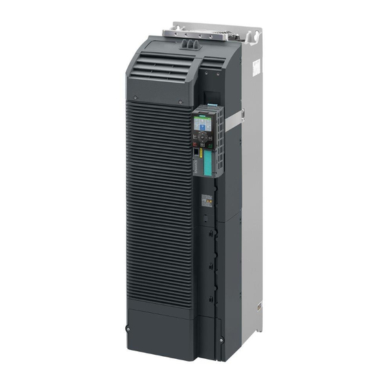
Sinamics g120 built-in unit power module
Hide thumbs
Also See for PM240-2:
- Hardware installation manual (144 pages) ,
- Installation manual (176 pages) ,
- Hardware installation instructions (2 pages)
Table of Contents
Table of Contents

Related Manuals for Siemens PM240-2


Summary of Contents for Siemens PM240-2
- Page 3 ___________________ Power Module PM240-2 Changes in this manual ___________________ Fundamental safety instructions ___________________ SINAMICS Introduction ___________________ Installing/mounting SINAMICS G120 Power Module PM240-2 ___________________ Connecting-up ___________________ Service and maintenance Hardware Installation Manual ___________________ Technical data ___________________ Spare parts and accessories ___________________...
- Page 4 Note the following: WARNING Siemens products may only be used for the applications described in the catalog and in the relevant technical documentation. If products and components from other manufacturers are used, these must be recommended or approved by Siemens. Proper transport, storage, installation, assembly, commissioning, operation and maintenance are required to ensure that the products operate safely and without any problems.
-
Page 5: Table Of Contents
Avoiding electromagnetic interference ..................50 5.3.2 Avoiding electromagnetic influence (EMI) ................50 5.3.3 Installing the converter in compliance with EMC rules ............53 5.3.4 EMC-compliant cabinet design ....................54 5.3.5 Equipotential bonding ......................55 Power Module PM240-2 Hardware Installation Manual, 12/2015, A5E33294624B AD... - Page 6 Fan replacement FSA … FSC ....................62 6.3.2 Fan replacement FSD … FSF ....................63 Technical data ............................65 High overload - low overload PM240-2 .................. 66 Cable cross-sections and tightening torques ................. 68 Technical data, 200 V inverters ..................... 69 7.3.1 General data, 200 V inverters ....................
- Page 7 Manuals and technical support ..................... 123 A.1.1 Manuals for your inverter ...................... 123 A.1.2 Configuring support ....................... 124 A.1.3 Product Support ........................125 Disposal ..........................125 Standards ..........................126 Abbreviations ........................127 Index..............................129 Power Module PM240-2 Hardware Installation Manual, 12/2015, A5E33294624B AD...
- Page 8 Table of contents Power Module PM240-2 Hardware Installation Manual, 12/2015, A5E33294624B AD...
-
Page 9: Changes In This Manual
Changes in this manual With respect to the PM240-2 Power Modules Manual, Edition 07/2015 The manual was expanded to include FSF Power Modules. 690 V inverters: 75 kW … 132 kW 400 V inverters: 75 kW … 132 kW 200 V inverters: 37 kW … 55 KW... - Page 10 Changes in this manual Power Module PM240-2 Hardware Installation Manual, 12/2015, A5E33294624B AD...
-
Page 11: Fundamental Safety Instructions
Touching live components can result in death or severe injury. • Only use power supplies that provide SELV (Safety Extra Low Voltage) or PELV- (Protective Extra Low Voltage) output voltages for all connections and terminals of the electronics modules. Power Module PM240-2 Hardware Installation Manual, 12/2015, A5E33294624B AD... - Page 12 • Install devices without a protective housing in a metal control cabinet (or protect the device by another equivalent measure) in such a way that contact with fire is prevented. • Ensure that smoke can only escape via controlled and monitored paths. Power Module PM240-2 Hardware Installation Manual, 12/2015, A5E33294624B AD...
- Page 13 Power Module PM240-2 Hardware Installation Manual, 12/2015, A5E33294624B AD...
- Page 14 Note Important safety notices for Safety Integrated functions If you want to use Safety Integrated functions, you must observe the safety notices in the Safety Integrated manuals. Power Module PM240-2 Hardware Installation Manual, 12/2015, A5E33294624B AD...
-
Page 15: Safety Instructions For Electromagnetic Fields (Emf)
– Wearing ESD shoes or ESD grounding straps in ESD areas with conductive flooring • Only place electronic components, modules or devices on conductive surfaces (table with ESD surface, conductive ESD foam, ESD packaging, ESD transport container). Power Module PM240-2 Hardware Installation Manual, 12/2015, A5E33294624B AD... -
Page 16: Industrial Security
Siemens recommends strongly that you regularly check for product updates. For the secure operation of Siemens products and solutions, it is necessary to take suitable preventive action (e.g. cell protection concept) and integrate each component into a holistic, state-of-the-art industrial security concept. -
Page 17: Residual Risks Of Power Drive Systems
Inverters of the Open Type/IP20 degree of protection must be installed in a metal control cabinet (or protected by another equivalent measure) such that contact with fire inside and outside the inverter is not possible. Power Module PM240-2 Hardware Installation Manual, 12/2015, A5E33294624B AD... - Page 18 Assuming that conductive contamination at the installation site can definitely be excluded, a lower degree of cabinet protection may be permitted. For more information about residual risks of the components in a drive system, see the relevant sections in the technical user documentation. Power Module PM240-2 Hardware Installation Manual, 12/2015, A5E33294624B AD...
-
Page 19: Introduction
Manuals for your inverter (Page 123) STO independent of the Control Unit Using the PM240-2 Power Modules, frame sizes FSD, FSE and FSF, you can implement the "Safe Torque Off" safety function (STO), corresponding to PL e according to EN 13849-1 and SIL 3 according to IEC61508. -
Page 20: Component Specification According To Ul
Motors for 690 V Power Modules For the 690 V Power Modules, induction motors are permissible in the range from 50 % … 150 % of the inverter power without any restrictions. Power Module PM240-2 Hardware Installation Manual, 12/2015, A5E33294624B AD... -
Page 21: Installing/Mounting
Inverters for systems in the United States / Canada (UL/cUL) ● For configurations in conformance with UL/cUL, use the UL/cUL-approved fuses, Class J or Siemens 3NE1 semiconductor fuses, which are specified in this manual. Fuse types and characteristic values are described in the following sections:... - Page 22 = 2000 V ● Suitable for SPD applications, type 1 or type 2 Alternatively, use a surge protection device, article number 5SD7 424-1 from Siemens AG. Frame sizes FSD … FSF Overvoltage category OVC III must be ensured for all connections of the power circuit. This can mean that a surge suppressor must connected upstream on the line side.
-
Page 23: Power Losses And Air Cooling Requirements
4. Ensure that the components have the specified clearances with respect to one another. 5. Ensure that the components are provided with adequate cooling air through the cooling openings. 6. Use the appropriate air barriers to prevent cooling air short circuits Power Module PM240-2 Hardware Installation Manual, 12/2015, A5E33294624B AD... - Page 24 When you use PT Power Modules, the majority of the power loss is dissipated through the heatsink located outside the control cabinet. The following losses occur in the cabinet ● FSA: 0.02 kW ● FSB: 0.045 kW ● FSC: 0.075 kW Power Module PM240-2 Hardware Installation Manual, 12/2015, A5E33294624B AD...
-
Page 25: Mounting The Power Modules
If you do not use the optional mounting frames, then you must ensure that the required degree of protection is complied with using other appropriate measures. You must mount the inverter on unpainted metal surfaces in order to comply with EMC requirements. Power Module PM240-2 Hardware Installation Manual, 12/2015, A5E33294624B AD... - Page 26 IEC 60529 or NEMA 12. Further measures may be necessary for particularly critical operating conditions. If condensation or conductive pollution can be excluded at the installation site, a lower degree of control cabinet protection may be permitted. Power Module PM240-2 Hardware Installation Manual, 12/2015, A5E33294624B AD...
-
Page 27: Dimension Drawings And Drilling Dimensions For Ip20 Power Modules
Module at the bot- 707.5 83.5 1107 The Power Modules can be mounted and operated side-by-side. For tolerance reasons, we rec- ommend a lateral clearance of approx. 1 mm. Power Module PM240-2 Hardware Installation Manual, 12/2015, A5E33294624B AD... - Page 28 With Control Unit: • + 26.5 + 8.5 + 29.5 With Control Unit and blanking cover / BOP-2: • + 37.5 + 19.5 + 40.5 With Control Unit and IOP: • Power Module PM240-2 Hardware Installation Manual, 12/2015, A5E33294624B AD...
-
Page 29: Hoisting Gear Fsd
Hoisting gear FSD ... PSF Hoisting gear When mounting Power Modules FSD and FSE, use crane lifting lugs and the appropri- ate hoisting gear. Weight of the Power Modules: Technical data (Page 65). Power Module PM240-2 Hardware Installation Manual, 12/2015, A5E33294624B AD... -
Page 30: Mounting Shield Plates
If you are using a brake relay to control a motor brake, then mount the brake relay at the rear of the lower shield plate before you attach the shield module to the inverter. Mounting and connecting the brake relay (Page 117) Power Module PM240-2 Hardware Installation Manual, 12/2015, A5E33294624B AD... - Page 31 If you are using the inverter without filter, then you do not require the EMC connecting bracket. In this case, you can attach the shield plate using three screws without the EMC connecting bracket. Power Module PM240-2 Hardware Installation Manual, 12/2015, A5E33294624B AD...
-
Page 32: Dimension Drawings And Drilling Dimensions For Pt Power Modules
117.7 53.1 117.7 53.1 The Power Modules can be mounted side-by-side. For tolerance reasons, we recommend a lateral clearance of 1 mm. Wall thickness of the control cabinet ≤ 3.5 mm Power Module PM240-2 Hardware Installation Manual, 12/2015, A5E33294624B AD... - Page 33 Drilling dimensions and dimensions for Cooling air clearances Fixing the control cabinet cutout (mm) (mm) Bottom Front 8 x M5 / 3.5 147.5 34.5 8 x M5 / 3.5 30.5 10 x M5 / 3.5 Power Module PM240-2 Hardware Installation Manual, 12/2015, A5E33294624B AD...
-
Page 34: Mounting The Shield Plate
Depending on the particular application, additional components may be required for your system. Information about additional components is provided in the following Sections: Connection overview (Page 42) Optional accessories (Page 99). Power Module PM240-2 Hardware Installation Manual, 12/2015, A5E33294624B AD... -
Page 35: Connecting-Up
To protect against indirectly touching part of the motor circuit of an inverter and to automatically shut down in the case of a fault according to DIN EN 60364-4-41 (VDE 0100- 410). (http://support.automation.siemens.com/WW/view/en/103474630) Power Module PM240-2 Hardware Installation Manual, 12/2015, A5E33294624B AD... - Page 36 (RCM) with the following properties and secondary conditions: – You are using a super-resistant RCD/RCM, type B with a tripping current of 300 mA. e.g. a SIQUENCE circuit breaker from Siemens. – Only one inverter is supplied from each RCD/RCM –...
-
Page 37: Line And Motor Connection
The machine manufacturer must ensure that in operation the voltage drop between the transformer input terminals and the inverter with rated values is less than 4%. The inverter is designed for the following power distribution systems according to IEC 60364- 1 (2005). Power Module PM240-2 Hardware Installation Manual, 12/2015, A5E33294624B AD... - Page 38 – Operation on TN line systems > 600 V and grounded line conductor not permissible. Examples for inverters connected to a TN line system Figure 5-1 TN line supply with separate transfer of N and PE and with a grounded neutral point Power Module PM240-2 Hardware Installation Manual, 12/2015, A5E33294624B AD...
- Page 39 UL, operation on a TT line system is not permissible. Examples for inverters connected to a TT line system Figure 5-2 TT line system with neutral conductor N and with grounded neutral point Power Module PM240-2 Hardware Installation Manual, 12/2015, A5E33294624B AD...
- Page 40 In some instances, even for a ground fault, the inverter should still remain functional. In cases such as these, you must install an output reactor. This prevents an overcurrent trip or damage to the drive. Power Module PM240-2 Hardware Installation Manual, 12/2015, A5E33294624B AD...
-
Page 41: Dimensioning The Protective Conductor
For a cross-section of the line supply cable ≥ 6 mm², cross-section = 6 mm² suffices for the protective con- ductor. ④ The protective conductor must have at least the same cross-section as the motor cable of the inverter. Power Module PM240-2 Hardware Installation Manual, 12/2015, A5E33294624B AD... -
Page 42: Connection Overview
FSA … FSC, 3 AC 400 V, there are external filters (Class B) for increased EMC requirements. Line filter (Page 107) Figure 5-4 Block diagram of the inverter Figure 5-5 Connecting PM240-2 Power Modules, 3 AC 200 V / 400 V /690 V Power Module PM240-2 Hardware Installation Manual, 12/2015, A5E33294624B AD... -
Page 43: Motor Cable Length
Connecting-up 5.1 Line and motor connection Figure 5-6 Connecting PM240-2 Power Modules, 200 V to 1 AC - only FSA ... FSC Note Connecting PM240-2 Power Modules, 200 V to 1 AC - only FSA ... FSC For the 200 V versions and single-phase line systems, connect the phase conductor and neutral conductor to any two of the terminals L1, L2, L3. -
Page 44: Motor Connection
Power Module with an external Class B line filter and an output reactor. 5.1.5 Motor connection Star and delta connection Siemens motors have a diagram inside the terminal box showing both connection meth- ods: • Star connection (Y) •... -
Page 45: Connection Terminals At The Inverter
The connectors are designed so that they cannot be accidentally interchanged. ① Line connectors ② Motor connection plug ③ Connection plug for a braking resistor ④ Release lever Power Module PM240-2 Hardware Installation Manual, 12/2015, A5E33294624B AD... - Page 46 Removing covers Frame size FSF: Use a suitable tool to knock out the openings for the power connection. We we recommend side cutters or a saw with a fine saw blade. Power Module PM240-2 Hardware Installation Manual, 12/2015, A5E33294624B AD...
- Page 47 5.1 Line and motor connection Terminal arrangement Figure 5-7 Line and motor connection PM240-2, FSF Connecting DC link or braking resistor You can use rubber cable glands when connecting the DC link and braking resistor. A cable gland is already integrated to connect the braking resistor. For the DC link connection, open the knockout opening and insert the cable gland.
- Page 48 1. Ensure that the device is in a no-voltage condition and the DC link is discharged. 2. When available, remove the covers. 3. Establish the connections. 4. Reattach the covers before you connect the power. You have established the connections. Power Module PM240-2 Hardware Installation Manual, 12/2015, A5E33294624B AD...
-
Page 49: Sto Via Power Module Terminals
Connecting-up 5.2 STO via Power Module terminals STO via Power Module terminals Safe Torque Off (STO) for the PM240-2 Using the PM240-2 Power Modules, frame siz- es FSD, FSE and FSF, you can implement the "Safe Torque Off" safety function (STO), corre- sponding to PL e according to EN 13849-1 and SIL 3 according to IEC61508. -
Page 50: Emc-Compliant Installation
● For screw connections onto painted or anodized surfaces, establish a good conductive contact using one of the following methods: – Use special (serrated) contact washers that cut through the painted or anodized surface. – Remove the insulating coating at the contact locations. Power Module PM240-2 Hardware Installation Manual, 12/2015, A5E33294624B AD... - Page 51 ● Route signal and data cables as well as the associated equipotential bonding cables parallel and as close to one another as possible. ● Connect the cable shields as closely as possible to the point where the cable enters the control cabinet. Power Module PM240-2 Hardware Installation Manual, 12/2015, A5E33294624B AD...
- Page 52 ● Only use metallic or metallized connectors for the plug connections for shielded data cables (e.g. PROFIBUS connection). Further information You can find additional information about the EMC installation guidelines under (http://support.automation.siemens.com/WW/view/en/60612658): Power Module PM240-2 Hardware Installation Manual, 12/2015, A5E33294624B AD...
-
Page 53: Installing The Converter In Compliance With Emc Rules
② shielded motor cable with hose clamp for shielding and strain relief ③ Shielded cable for the Control Unit with shielding using a serrated strip on the CU shield plate. Power Module PM240-2 Hardware Installation Manual, 12/2015, A5E33294624B AD... -
Page 54: Emc-Compliant Cabinet Design
Connect the shields to the cabinet ground through a large surface area and low ohmic connection. Ensure that there are no potential differences between these zones, to avoid inadmissibly high equalization currents flowing through the cable shields. Power Module PM240-2 Hardware Installation Manual, 12/2015, A5E33294624B AD... -
Page 55: Equipotential Bonding
Route finely stranded or braided copper conductors in parallel to the motor cable with the shortest possible distance between them: ● in older systems with already existing unshielded cables ● for cables with poor high-frequency properties of the shield ● for poor grounding systems Power Module PM240-2 Hardware Installation Manual, 12/2015, A5E33294624B AD... - Page 56 Connect the shield through a large contact surface and ground ⑤ Connect the shield through an electrically conductive heavy-gauge threaded joint (gland) and ground Figure 5-9 Grounding and high-frequency equipotential bonding measures in the drive system and in the plant Power Module PM240-2 Hardware Installation Manual, 12/2015, A5E33294624B AD...
- Page 57 The following diagram shows the additional measures for high-frequency equipotential bonding Figure 5-10 Additional measures for high frequency equipotential bonding of the drive system Further information You can find additional information about the EMC installation guidelines at (https://support.industry.siemens.com/cs/ww/de/view/60612658/en): Power Module PM240-2 Hardware Installation Manual, 12/2015, A5E33294624B AD...
- Page 58 Connecting-up 5.3 EMC-compliant installation Power Module PM240-2 Hardware Installation Manual, 12/2015, A5E33294624B AD...
-
Page 59: Service And Maintenance
WARNING Danger due to incorrect repair Repairs may only be carried out by Siemens Service, by repair centers authorized by Siemens or by authorized personnel who are thoroughly acquainted with all the warnings and operating procedures contained in this manual. -
Page 60: Maintenance
Note The actual maintenance intervals depend on the installation and operating conditions. Siemens offers its customers support in the form of service contracts. For further information, contact your Siemens regional office or sales office. Power Module PM240-2... -
Page 61: Commissioning After A Long Storage Time
The date of manufacture of the inverter is encrypted in positions 3 - 6 of the serial number. Figure 6-2 Data of manufacture in the serial number (example, April 21, 2013) Power Module PM240-2 Hardware Installation Manual, 12/2015, A5E33294624B AD... -
Page 62: Replacing A Fan
3. Remove the shield plate from the Power Module. 4. Remove the fan module from the Power Module as shown in the diagram. 5. Install the new fan module in the inverse sequence. You have replaced the fan module. Power Module PM240-2 Hardware Installation Manual, 12/2015, A5E33294624B AD... -
Page 63: Fan Replacement Fsd
2. Remove the fan module from the Power Module as shown in the diagram. 3. Install the new fan module in the inverse sequence. You have replaced the fan module Power Module PM240-2 Hardware Installation Manual, 12/2015, A5E33294624B AD... - Page 64 Service and maintenance 6.3 Replacing a fan Power Module PM240-2 Hardware Installation Manual, 12/2015, A5E33294624B AD...
-
Page 65: Technical Data
Power loss for Power Modules FSD and FSF The values specified for the power loss are typical values at 90% of the rated speed and 100% of the load corresponding to Low Overload. Power Module PM240-2 Hardware Installation Manual, 12/2015, A5E33294624B AD... -
Page 66: High Overload - Low Overload Pm240-2
Technical data 7.1 High overload - low overload PM240-2 High overload - low overload PM240-2 Typical inverter load cycles Figure 7-1 "Low Overload" and "High Overload" load cycles Overload capability is the property of the inverter to temporarily supply a current that is higher than the rated current to accelerate a load. - Page 67 Technical data 7.1 High overload - low overload PM240-2 Load cycles and typical applications: "Low Overload" load cycle "High Overload" load cycle The "Low Overload" load cycle assumes a The "High Overload" load cycle permits, for uniform base load with low requirements reduced base load, dynamic accelerating placed on brief accelerating p phases.
-
Page 68: Cable Cross-Sections And Tightening Torques
1 … 2*4/0 AWG: 210 lbf.in -- DC link with cable lugs according to SN71322 Braking resistor 25 … 70 mm : 8 … 10 Nm 6 … 3/0 AWG: 88.5 lbf in 25 mm Power Module PM240-2 Hardware Installation Manual, 12/2015, A5E33294624B AD... -
Page 69: Technical Data, 200 V Inverters
Branch protection and short-circuit strength according to UL and IEC (https://support.industry.siemens.com/cs/ww/en/view/109479152) Electromagnetic compati- Devices with integrated filter are suitable for Category C2 environments. bility according to IEC/EN 61800-3 Braking methods DC braking, compound braking, dynamic braking with integrated braking chopper Power Module PM240-2 Hardware Installation Manual, 12/2015, A5E33294624B AD... - Page 70 4000 m above sea level Restrictions for special ambient conditions (Page 92) Approvals FSA … FSC cULus, CE, C-tick, KCC FSD … FSF cULus, CE, C-tick, SEMI F47, KCC, WEEE, RoHS, EAC Power Module PM240-2 Hardware Installation Manual, 12/2015, A5E33294624B AD...
-
Page 71: Specific Technical Data, 200 V Inverters
Additional components for branch protection: Branch protection and short-circuit strength according to UL and IEC (https://support.industry.siemens.com/cs/ww/en/view/109479152) Table 7- 2 PM240-2, IP20, frame sizes A, 1 AC / 3 AC 200 V … 240 V Article No. - without filter 6SL3210… …1PB13-0UL0 …1PB13-8UL0 Article No. - Page 72 Technical data 7.3 Technical data, 200 V inverters Table 7- 3 PM240-2, PT, frame sizes A, 1 AC / 3 AC 200 V … 240 V Article No. - without filter 6SL3211… …1PB13-8UL0 Article No. - with filter 6SL3211… …1PB13-8AL0 LO base load power 0.75 kW...
- Page 73 3.4 kg Weight with filter 3.7 kg 1) approx. 0.08 through the heatsink Table 7- 6 PM240-2, IP 20, frame sizes C, 1 AC / 3 AC 200 V … 240 V Article No. - without filter 6SL3210… ...1PB21-4UL0 …1PB21-8UL0 Article No.
- Page 74 Technical data 7.3 Technical data, 200 V inverters Table 7- 7 PM240-2, PT, frame sizes C, 1 AC / 3 AC 200 V … 240 V Article No. - without filter 6SL3211… ...1PB21-8UL0 Article No. - with filter …1PB21-8AL0 6SL3211…...
- Page 75 Technical data 7.3 Technical data, 200 V inverters Table 7- 9 PM240-2, IP20, FSD, 3 AC 200 V … 240 V Article No. - without filter 6SL3210-… …1PC24-2UL0 …1PC25-4UL0 …1PC26-8UL0 LO base load power 11 kW 15 kW 18.5 kW...
-
Page 76: Current Derating Depending On The Pulse Frequency, 200 V Inverters
52.0 46.8 41.6 6SL3210-1PC31-3❒L0 110.5 91.0 6SL3210-1PC31-6❒L0 130.9 107.8 6SL3210-1PC31-8❒L0 151.3 124.6 The permissible motor cable length depends on the particular cable type and the pulse frequency that has been selected Power Module PM240-2 Hardware Installation Manual, 12/2015, A5E33294624B AD... -
Page 77: Technical Data, 400 V Inverters
Branch protection and short-circuit strength according to UL and IEC (https://support.industry.siemens.com/cs/ww/en/view/109479152) Electromagnetic compati- Devices with integrated filter are suitable for Category C2 environments. bility according to IEC/EN 61800-3 Braking methods DC braking, compound braking, dynamic braking with integrated braking chopper Power Module PM240-2 Hardware Installation Manual, 12/2015, A5E33294624B AD... - Page 78 4000 m above sea level Restrictions for special ambient conditions (Page 92) Approvals FSA … FSC cULus, CE, C-tick, KCC FSD … FSF cULus, CE, C-tick, SEMI F47, KCC, WEEE, RoHS, EAC Power Module PM240-2 Hardware Installation Manual, 12/2015, A5E33294624B AD...
-
Page 79: Specific Technical Data, 400 V Inverters
The fuses listed in the following tables are examples of suitable fuses. Additional components for branch protection: Branch protection and short-circuit strength according to UL and IEC (https://support.industry.siemens.com/cs/ww/en/view/109479152) Table 7- 12 PM240-2, IP20, frame sizes A, 3-phase 380 … 480 VAC Article no. - without filter 6SL3210… …1PE11-8UL1 …1PE12-3UL1 …1PE13-2UL1 Article no. - Page 80 Technical data 7.4 Technical data, 400 V inverters Table 7- 13 PM240-2, IP20, frame sizes A, 3-phase 380 … 480 VAC Article no. - without filter 6SL3210… …1PE14-3UL1 …1PE16-1UL1 …1PE18-0UL1 Article no. - with filter 6SL3210… …1PE14-3AL1 …1PE16-1AL1 …1PE18-0AL1 LO base load power 1.5 kW...
- Page 81 Technical data 7.4 Technical data, 400 V inverters Table 7- 15 PM240-2, IP20, frame sizes B, 3-phase 380 … 480 VAC Article no. - without filter 6SL3210… …1PE21-1UL0 …1PE21-4UL0 …1PE21-8UL0 Article no. - with filter 6SL3210… …1PE21-1AL0 …1PE21-4AL0 …1PE21-8AL0 LO base load power 4.0 kW...
- Page 82 Technical data 7.4 Technical data, 400 V inverters Table 7- 17 PM240-2, IP20, frame sizes C, 3-phase 380 … 480 VAC Article no. - without filter 6SL3210… …1PE22-7UL0 …1PE23-3UL0 Article no. - with filter 6SL3210… …1PE22-7AL0 …1PE23-3AL0 LO base load power 11.0 kW...
- Page 83 Technical data 7.4 Technical data, 400 V inverters Table 7- 19 PM240-2, IP20, FSD, 3 AC 380 V … 480 V Article No. - without filter 6SL3210-… …1PE23-8UL0 …1PE24-5UL0 …1PE26-0UL0 Article No. - with filter 6SL3210-… …1PE23-8AL0 …1PE24-5AL0 …1PE26-0AL0 LO base load power 18.5 kW...
- Page 84 Technical data 7.4 Technical data, 400 V inverters Table 7- 21 PM240-2, IP20, FSE, 3 AC 380 V … 480 V Article No. - without filter 6SL3210-… …1PE28-8UL0 …1PE31-1UL0 Article No. - with filter 6SL3210-… …1PE28-8AL0 …1PE31-1AL0 LO base load power...
- Page 85 Technical data 7.4 Technical data, 400 V inverters Table 7- 23 PM240-2, IP20, FSF, 3 AC 380 V … 480 V Article No. - without filter 6SL3210-… …1PE32-5UL0 Article No. - with filter 6SL3210-… …1PE32-5AL0 LO base load power 132 kW...
-
Page 86: Current Derating Depending On The Pulse Frequency, 400 V Inverters
40.5 6SL3210-1PE31-1❒L0 93.5 49.5 6SL3210-1PE31-5❒L0 123.25 108.75 6SL3210-1PE31-8❒L0 151.3 133.5 6SL3210-1PE32-1❒L0 6SL3210-1PE32-5❒L0 The permissible motor cable length depends on the particular cable type and the pulse frequency that has been selected Power Module PM240-2 Hardware Installation Manual, 12/2015, A5E33294624B AD... -
Page 87: Technical Data, 690 V Inverters
Protected against damaging chemical substance, according to environmental Class 3C3 ing to EN 60721-3-3 Temperature during stor- -40 °C … +70 °C age according to EN 60721-3-3 Cooling air clean and dry air Relative humidity < 95% Power Module PM240-2 Hardware Installation Manual, 12/2015, A5E33294624B AD... - Page 88 4000 m above sea level Restrictions for special ambient conditions (Page 92) Approvals cULus, CE, C-tick, SEMI F47, KCC,WEEE, RoHS, EAC Dependent on the input voltage and output power 690 V inverters Power Module PM240-2 Hardware Installation Manual, 12/2015, A5E33294624B AD...
-
Page 89: Specific Technical Data, 690 V Inverters
The fuses listed in the following tables are examples of suitable fuses. Additional components for branch protection: Branch protection and short-circuit strength according to UL and IEC (https://support.industry.siemens.com/cs/ww/en/view/109479152) Table 7- 24 PM240-2, IP20, FSD, 3 AC 500 V … 690 V Article No. - without filter 6SL3210-… …1PH21-4UL0 …1PH22-0UL0 …1PH22-3UL0 Article No. - Page 90 Technical data 7.5 Technical data, 690 V inverters Table 7- 26 PM240-2, IP20, FSE, 3 AC 500 V … 690 V Article No. - without filter 6SL3210-… …1PH25-2UL0 …1PH26-2UL0 Article No. - with filter 6SL3210-… …1PH25-2AL0 …1PH26 -2AL0 LO base load power...
-
Page 91: Current Derating Depending On The Pulse Frequency, 690 V Inverters
Technical data 7.5 Technical data, 690 V inverters Table 7- 28 PM240-2, IP20, FSF, 3 AC 500 V … 690 V Article No. - without filter 6SL3210-… …1PH31-4UL0 Article No. - with filter 6SL3210-… …1PH31 4AL0 LO base load power... -
Page 92: Restrictions For Special Ambient Conditions
Operating state that is permissible for less than 1 % of the operating time. Current de-rating depending on the ambient operating temperature The Control Unit and operator panel can restrict the maximum permissible operating ambient temperature of the Power Module. Power Module PM240-2 Hardware Installation Manual, 12/2015, A5E33294624B AD... - Page 93 TN line supply for 690 V Power Modules for installation attitudes extending from 2000 m to 4000 m For 690 V Power Modules, the TN line system must be established with grounded neutral point through an isolating transformer. Power Module PM240-2 Hardware Installation Manual, 12/2015, A5E33294624B AD...
-
Page 94: Electromagnetic Compatibility Of The Inverter
Drive systems with a rated voltage ≥ 1,000 V, with an LO output current ≥ 400 A, or for use in complex systems in the second environment Drive systems which correspond to category C4 may only be installed in the second environment. Power Module PM240-2 Hardware Installation Manual, 12/2015, A5E33294624B AD... - Page 95 Note Expert An expert is a person or organization with the necessary experience for installing and/or commissioning drive systems (Power Drive Systems - PDS), including the associated EMC aspects. Power Module PM240-2 Hardware Installation Manual, 12/2015, A5E33294624B AD...
-
Page 96: Assigning The Inverter To Emc Categories
C3 (field-based high-frequency disturbance variables). Second environment - category C2 Inverters with integrated filter are suitable for use in the second environment, Category C2. Power Module PM240-2 Hardware Installation Manual, 12/2015, A5E33294624B AD... -
Page 97: Harmonics
FSD … FSF, 200 V FSD … FSF, 400 V FSD … FSF, 690 V Typical harmonic currents as a % referred to the LO input current for U Typical harmonic currents as a % Power Module PM240-2 Hardware Installation Manual, 12/2015, A5E33294624B AD... -
Page 98: Emc Limit Values In South Korea
Please note that the final statement on compliance with the standard is given by the respective label attached to the individual unit. You can find the Configuration Manual "EMC installation guidelines" under (http://support.automation.siemens.com/WW/view/en/60612658) Power Module PM240-2 Hardware Installation Manual, 12/2015, A5E33294624B AD... -
Page 99: Spare Parts And Accessories
● Line reactor - only frame sizes FSA … FSC ● Line filter ● Braking resistor ● Brake Relay and Safe Brake Relay ● Output reactors Connection components Connection overview for the electrical components Connection overview (Page 42). Power Module PM240-2 Hardware Installation Manual, 12/2015, A5E33294624B AD... -
Page 100: Mounting Frames For Pt Power Modules
The IP55 degree of protection for the PT devices can only be guaranteed, if the applicable Siemens mounting frame is used and this is correctly installed. The specified tightening torque for the fixing screws (3.5 Nm) is also only valid for Siemens mounting frames. Power Module PM240-2... - Page 101 Spare parts and accessories 8.2 Optional accessories Dimension drawings Figure 8-1 Mounting frames_FSA - FSB Power Module PM240-2 Hardware Installation Manual, 12/2015, A5E33294624B AD...
- Page 102 Spare parts and accessories 8.2 Optional accessories Figure 8-2 Mounting frames_FSC Power Module PM240-2 Hardware Installation Manual, 12/2015, A5E33294624B AD...
-
Page 103: Line Reactor
If the line impedance is below 1%, you must install a line reactor to achieve the optimum service life of your inverter. 8.2.2.1 Line reactors for PM240-2, 400 V Mounting position Clearances to other devices For a line reactor, a minimum clearance to other devices must be maintained on all sides. - Page 104 Spare parts and accessories 8.2 Optional accessories Dimensions and drilling patterns 0.55 kW … 1.1 kW Dimensions [mm] Drilling pattern [mm] 1.5 kW … 4.0 kW Dimensions [mm] Drilling pattern [mm] Power Module PM240-2 Hardware Installation Manual, 12/2015, A5E33294624B AD...
- Page 105 M4 (3 Nm / 26.5 lbf in) M5 (5 Nm / 44.3 lbf in) M5 (5 Nm / 44.3 lbf in) Degree of protection IP20 IP20 IP20 IP20 Weight 1.1 kg 2.1 kg 2.95 kg 7.80 kg Power Module PM240-2 Hardware Installation Manual, 12/2015, A5E33294624B AD...
-
Page 106: Line Reactors For Pm240-2, 200 V
6SL3210-1PE22-7☐L0, 6SL321☐-1PC22-2☐L0 6SL321☐-1PE23-3☐L0 6SL3210-1PC22-8☐L0 8.2.2.2 Line reactors for PM240-2, 200 V We recommend the following or similar products as line reactors for inverters with input voltages 1 AC 200 V: ● FSA: NKE 10 / 2.93 (Block company) ● FSB NKE 25 / 1.17 (Block company) -
Page 107: Line Filter
Line filter (Class B) 400 V Power Modules 6SL3203-0BE17-7BA0 6SL3210-1PE11-8UL1 6SL3210-1PE12-3UL1 6SL3210-1PE13-2UL1 6SL3210-1PE14-3UL1 6SL3210-1PE16-1UL1 6SL321☐-1PE18-0UL1 6SL3203-0BE21-8BA0 6SL3210-1PE21-1UL0 6SL3210-1PE21-4UL0 6SL321☐-1PE21-8UL0 6SL3203-0BE23-8BA0 6SL3210-1PE22-7UL0 6SL321☐-1PE23-3UL0 ☐Stands for 1 or 2: 1: Chassis device 2: PT device Power Module PM240-2 Hardware Installation Manual, 12/2015, A5E33294624B AD... -
Page 108: Braking Resistor
The following data are applicable for devices, frame sizes FSA … FSC. The clearances for braking resistors for devices, frame sizes FSD … FSF are specified in the documentation, which is supplied with the braking resistor. Power Module PM240-2 Hardware Installation Manual, 12/2015, A5E33294624B AD... - Page 109 Minimum clearances for the braking resistor when mounting on a flat surface and for wall/panel mounting Keep shaded areas free of any devices and components. Dimensions and drilling patterns Figure 8-5 Braking resistor Power Module PM240-2 Hardware Installation Manual, 12/2015, A5E33294624B AD...
- Page 110 M5 / 6 Nm 13.5 (FSE) Use the screws, nuts and washers when fixing the braking resistors *) This braking resistor comprises two components, which must be connected in parallel on the plant/system side Power Module PM240-2 Hardware Installation Manual, 12/2015, A5E33294624B AD...
-
Page 111: Connect The Temperature Contact Of The Braking Resistor
Note Braking resistors FSD … FSF Only use braking resistors that are UL approved, and have successfully passed the "Abnormal Operation Test" according to UL 508. Power Module PM240-2 Hardware Installation Manual, 12/2015, A5E33294624B AD... - Page 112 Spare parts and accessories 8.2 Optional accessories Braking resistors for PM240-2, 200 V Table 8- 6 Technical data Article No. Maximum Connection Degree of Power Module sistance power, P protection Rated power Weight Article Nos. Frame size JJY:023146720008 200 Ω...
- Page 113 Spare parts and accessories 8.2 Optional accessories Braking resistors for PM240-2, 400 V Table 8- 7 Technical data Article number Maximum Connection Degree of Power Module sistance power, P R1 / R2 protection Rated power Weight Article Nos. Frame size 6SL3201-0BE14-3AA0 370 Ω...
- Page 114 Spare parts and accessories 8.2 Optional accessories Braking resistors for PM240-2, 690 V Table 8- 8 Technical data Article number Maximum Connection Degree of Power Module sistance power, P R1 / R2 protection Rated power Weight Article Nos. Frame size JJY:023424020002 31 Ω...
-
Page 115: Connecting A Motor Holding Brake
Brake Module and to the inverter as shown below. If you are using your own cable, ensure that the cable is insulated and rated for 600 V. Power Module PM240-2 Hardware Installation Manual, 12/2015, A5E33294624B AD... -
Page 116: Mounting And Connecting The Brake Relay
PELV circuit. 8.2.5.2 Mounting and connecting the brake relay The Brake Relay must be connected to the protective conductor if the motor brake is supplied from a PELV circuit. Power Module PM240-2 Hardware Installation Manual, 12/2015, A5E33294624B AD... -
Page 117: Technical Data Of The Brake Relay
Connecting the Brake Relay to the inverter The connector for the Brake Relay is located at the front of the Power Module. Lay the cable harness for the Brake Relay in the cable routing. Power Module PM240-2 Hardware Installation Manual, 12/2015, A5E33294624B AD... -
Page 118: Output Reactor
Output reactor - clearances Mounting position Clearances to other devices Keep shaded areas free of any devices and components. Figure 8-8 Minimum clearances of the output reactor to other devices, space-saving mounting examples Power Module PM240-2 Hardware Installation Manual, 12/2015, A5E33294624B AD... - Page 119 Spare parts and accessories 8.2 Optional accessories Dimensions and drilling patterns 0.55 kW … 2.2 kW Dimensions [mm] Drilling pattern [mm] 3.0 kW … 4.0 kW Dimensions [mm] Drilling pattern [mm] Power Module PM240-2 Hardware Installation Manual, 12/2015, A5E33294624B AD...
- Page 120 Spare parts and accessories 8.2 Optional accessories 5.5 kW … 7.5 kW Dimensions [mm] Drilling pattern [mm] 11 kW … 18.5 kW Dimensions [mm] Drilling pattern [mm] Power Module PM240-2 Hardware Installation Manual, 12/2015, A5E33294624B AD...
- Page 121 400 V Power Modules 200 V Power Modules 6SL3202-0AE16-1CA0 6SL3210-1PE11-8☐L1 6SL3210-1PB13-0☐L0 6SL3210-1PE12-3☐L1 6SL321☐-1PB13-8☐L0 6SL3210-1PE13-2☐L1 6SL3210-1PB15-5☐L0 6SL3210-1PE14-3☐L1 6SL3210-1PE16-1☐L1 6SL3202-0AE18-8CA0 6SL321☐-1PE18-0UL1 6SL3210-1PB17-4☐L0 6SL3202-0AE21-8CA0 6SL3210-1PE21-1☐L0 6SL321☐-1PB21-0☐L0 6SL3210-1PE21-4☐L0 6SL3210-1PB21-4☐L0 6SL321☐-1PE21-8☐L0 6SL321☐-1PB21-8☐L0 6SL3202-0AE23-8CA0 6SL3210-1PE22-7☐UL0 6SL321☐-1PC22-2☐L0 6SL321☐-1PE23-3☐L0 6SL3210-1PC22-8☐L0 Power Module PM240-2 Hardware Installation Manual, 12/2015, A5E33294624B AD...
- Page 122 Spare parts and accessories 8.2 Optional accessories Power Module PM240-2 Hardware Installation Manual, 12/2015, A5E33294624B AD...
-
Page 123: Appendix
The technical overviewEMC - elec- 103704610 Guidelines and standards, tromagnetic compatibility EMC-compliant control cabi- net design Configuration ManualEMC installation 60612658 EMC-compliant control cabi- guideline net design, potential equaliza- tion and cable routing Power Module PM240-2 Hardware Installation Manual, 12/2015, A5E33294624B AD... -
Page 124: Configuring Support
Ordering data and technical information for SINAMICS G inverters. Available languages: Catalog D31 for download or online catalog (Industry Mall): All about SINAMICS G120 (www.siemens.com/sinamics-g120) SIZER The configuration tool for SINAMICS, MICROMASTER and DYNAVERT T drives, motor starters, as well as SINUMERIK, SIMOTION controllers and SIMATIC technology... -
Page 125: Product Support
Disposal Protecting the environment and preserving its resources are corporate goals of the highest priority for Siemens. Our worldwide environmental management system according to ISO 14001 ensures compliance with legislation and sets high standards in this regard. Environmentally friendly design, technical safety and health protection are always firm goals, even at the product development stage. -
Page 126: Standards
EMC Directive as defined by the EMC Product Standard for Power Drive Systems EN 61800-3. ISO 9001 Siemens I DT MC operates a quality management system which complies with the requirements of ISO 9001. Underwriters Laboratories The device is listed by UL and CUL for power conversion in an environment with the pollution degree 2. -
Page 127: Abbreviations
Operating instructions PELV Protective extra low voltage Power Module Personnel protective equipment Push-through technology RCCB Residual-current operated circuit breaker Residual current device Radio frequency interference SELV Safety extra-low voltage Variable torque Power Module PM240-2 Hardware Installation Manual, 12/2015, A5E33294624B AD... -
Page 129: Index
Disposal, 125 Download manuals, 123 Drilling pattern, 104, 109, 119 Maintenance Cleaning, 60 Dirt, 60 Pollution, 60 Terminals, 60 Electrical installation, 35 Ventilation, 60 EMC, 54 Manual Collection, 123 Manuals, overview, 123 Power Module PM240-2 Hardware Installation Manual, 12/2015, A5E33294624B AD... - Page 130 Second environment, 94 Service life of the fan, 62 SIZER, 124 Standards EN 61800-3, 94, 96 EN 61800-3, 94, 96 Star/delta connection, 44 Support, 125 TN line system, 37 TT line system, 37 Power Module PM240-2 Hardware Installation Manual, 12/2015, A5E33294624B AD...