
Related Manuals for Siemens SICAM RTU


Summary of Contents for Siemens SICAM RTU
- Page 1 Preface, Table of Contents SICAM RTUs Installation System Components SICAM AK 3 Prepare Engineering User Manual Engineering via SICAM TOOLBOX II Service Automation Units and Automation Net- works Licensing Agreement DC2-028-2.03...
- Page 2 Disclaimer of Liability Copyright Although we have carefully checked the contents of this publication Copyright © Siemens AG 2016 for conformity with the hardware and software described, we cannot The reproduction, transmission or use of this document or its guarantee complete conformity since errors cannot be excluded.
- Page 3 References to Third-Party Web Sites Siemens is not responsible for the contents of third-party websites mentioned in this docu- ment, as well as the correctness of the publications and links. For all product information the respective manufacturer is responsible.
- Page 4 DC0-046-2 SICAM RTUs MODBUS Interoperability DC0-073-2 Ax 1703 IEC 60870-5-101/104 Interoperability DA0-046-2 You find current product information on our website: www.siemens.com/sicam. Further Support For more information, please contact our Customer Support Center: Phone: +49 (0)180 524 70 00 Fax: +49 (0)180 524 24 71...
- Page 5 Preface Notes on Safety This manual does not constitute a complete catalog of all safety measures required for operat- ing the equipment (module, device) in question because special operating conditions might require additional measures. However, it does contain notes that must be adhered to for your own personal safety and to avoid damage to property.
- Page 6 The equipment (device, module) must not be used for any other purposes than those de- scribed in the Catalog and the Technical Description. If it is used together with third-party de- vices and components, these must be recommended or approved by Siemens. Correct and safe operation of the product requires adequate transportation, storage, installa- tion, and mounting as well as appropriate use and maintenance.
-
Page 7: Open Source Software
Insofar as the applicable Open Source Software License Conditions provide for it you can or- der the source code of the Open Source Software from your Siemens sales contact - against payment of the shipping and handling charges - for a period of at least 3 years since purchase of the Product. - Page 8 Open Source Software SICAM RTUs, SICAM AK 3 User Manual Edition 07.2016, DC2-028-2.03...
-
Page 9: Table Of Contents
Table of Contents Open Source Software ....................7 Installation ........................17 Mechanical Design ..................18 1.1.1 CM-2844 Basic Board Rack, 9 Slots ............19 1.1.2 CM-2846 Basic Board Rack, 17 Slots ............19 1.1.3 CM-2848 Basic Board Rack, 17 Slots ............20 1.1.4 CM-2843 Expansion Board Rack, 16 Slots.......... - Page 10 Table of Contents 1.4.5.1.5 Dial-Up Traffic GSM................. 54 1.4.5.1.6 Serial communication with DMS (Digital Multiplex System) ....56 1.4.5.1.7 Serial communication – Direct connection with RS-232 ....58 1.4.5.2 LAN Communication (Ethernet TCP/IP) ..........60 1.4.5.3 Field bus Communication (PROFIBUS-DP) .......... 61 1.4.6 Cable Routing ...................
- Page 11 Table of Contents 2.2.1.2 Block Diagram ..................91 2.2.1.3 Pin Assignment ..................92 2.2.1.4 LED Display ..................94 2.2.2 CP-2019/PCCX26 ..................95 2.2.2.1 Front Panel ................... 95 2.2.2.2 Block Diagram ..................96 2.2.2.3 Pin Assignment ..................97 2.2.2.4 LED Displays: ..................98 Migration-Basic System Element ..............
- Page 12 Table of Contents 2.5.3 DO-2201/BISO25 ..................118 2.5.3.1 Front Panel..................118 2.5.3.2 Block Diagram ..................119 2.5.3.3 Pin Assignment .................. 120 2.5.3.4 External Circuitry ................121 2.5.3.5 I/O Assignment ................... 124 2.5.3.5.1 Outputs ..................124 2.5.4 DO-2210/PCCO2x, DO-2211/PCCO2x ............ 125 2.5.4.1 Front Panel..................
- Page 13 Table of Contents 2.8.1.1 Front Panel ..................158 2.8.1.2 Block Diagram ..................159 2.8.1.3 Pin Assignment and Display ............... 160 2.8.1.4 Configuration (Example) ..............161 2.8.2 CM-0842 ....................162 2.8.2.1 Front Panel ..................162 2.8.2.2 Configuration Switch S1 ..............162 2.8.2.3 Pin Assignment and Display ...............
- Page 14 Table of Contents 4.1.5.2 System-Technical Settings ..............189 4.1.5.2.1 Communication................189 4.1.5.2.2 Periphery ..................189 4.1.5.3 Process-Technical Settings ..............190 4.1.5.3.1 Levels .................... 190 4.1.5.3.2 Types .................... 190 4.1.5.3.3 Images ..................191 4.1.5.4 Decentralized Archiving (DEAR) ............192 4.1.6 Transform Parameters ................192 4.1.7 Import, Export and Backup of Engineering Data ........
- Page 15 Table of Contents Checks And System Displays ............... 213 5.2.1 Basic System Elements ................213 5.2.2 Protocol Elements ................... 217 5.2.3 Peripheral Elements ................218 Diagnosis ..................... 219 5.3.1 Distinction of the Error Types ..............219 5.3.2 Connection Possibilities for the Service............ 219 5.3.3 System Diagnosis ..................
- Page 16 Table of Contents 6.2.4 SICAM AK 3 as Telecontrol Substation with integrated Switch for External System connection .................. 248 6.2.5 SICAM AK 3 as Telecontrol Substation with integrated Switch for SICAM TOOLBOX II connection ................249 Application/Configuration of Static Routes ........... 250 6.3.1 General ....................
-
Page 17: Installation
Installation Contents Mechanical Design ..................18 Board rack Installation ..................22 Installation and Removal of Modules .............. 36 Setup of external Communication Connections ..........40 Wiring for the Reception of Time Signals ............64 Wiring Watchdog and Error ................70 Power Supply .................... -
Page 18: Mechanical Design
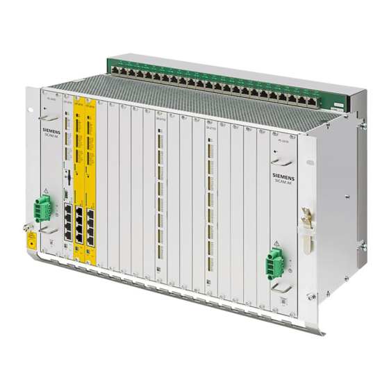
Installation Mechanical Design The system SICAM AK 3 consists of a board rack in double euro format with slots for the seat- ing of modules and power supplies. Mounting rack CM-2844 Mounting rack CM-2846 PS-263x CP-2016 DI-2110 DI-2 110 CP-2019 DI-2110 DO-221 0 AI-230 1 AI-2300... -
Page 19: Cm-2844 Basic Board Rack, 9 Slots
Installation 1.1.1 CM-2844 Basic Board Rack, 9 Slots The basic board rack CM-2844 has 9 slots for modules and 2 slots for power supplies in dou- ble euro format. It serves for the equipment of basic modules and peripheral modules. It can be used for rear panel assembly. -
Page 20: Cm-2848 Basic Board Rack, 17 Slots
Installation 1.1.3 CM-2848 Basic Board Rack, 17 Slots The basic board rack CM-2846 has 17 slots for modules and 2 slots for power supplies in double euro format. It serves for the equipment of basic modules and peripheral modules. It can be used for 19" (swing-)frame installation and rear panel assembly. This example shows a board rack for the 19"... -
Page 21: Cm-2847 Migration Board Rack, 17 Slot
Installation 1.1.5 CM-2847 Migration Board Rack, 17 Slot The migration board rack CM-2847 has 17 slots for modules and 2 slots for power supplies in double-Europe format. It serves for the equipment of basic modules and peripheral modules. The board rack is designed for 19“ (swing-) frame installation. In section 1.2.2, Space Requirement you can find information on the dimensions. -
Page 22: Board Rack Installation
Installation Board Rack Installation 1.2.1 Installation Location The system SICAM AK 3 can be used for the installation in a cabinet. Systems, which use a CM-2846 board rack, are primarily designed for the 19" (swing-) frame installation, but can optionally be expanded for rear panel installation. Systems, which use a CM-2844 board rack, are designed for the rear panel installation. -
Page 23: Cm-2844 - Rear Panel Installation
Installation 1.2.2.1 CM-2844 - Rear Panel Installation Cabinet rear panel Space needed for cabling PS-263x CP-2016 DI-2110 DO-2210 CP-2019 AI-2300 AI-2301 AI-2301 PS-263x SICAM AK SICAM AK minimum free space SICAM RTUs, SICAM AK 3 User Manual DC2-028-2.03, Edition 07.2016... -
Page 24: Cm-2846 - Rear Panel Installation
Installation 1.2.2.2 CM-2846 - Rear Panel Installation Cabinet rear panel Space needed for cabling PS-263x CP-2016 DI-2110 DI-2110 DI-2110 DI-2110 CP-2019 DO-2210 AI-2301 AI-2300 AI-2300 CP-2019 DI-2110 DI-2110 DI-2110 DO-2210 AI-2301 PS-263x SICAM AK SICAM AK minimum free space SICAM RTUs, SICAM AK 3 User Manual Edition 07.2016, DC2-028-2.03... -
Page 25: Cm-2848 - Rear Panel Installation
Installation 1.2.2.3 CM-2848 – Rear Panel Installation Cabinet rear panel Space needed for cabling PS-263x CP-2016 DI-2110 DI-2110 DI-2110 DI-2110 CP-2019 DO-2210 AI-2301 AI-2300 AI-2300 CP-2019 DI-2110 DI-2110 DI-2110 DO-2210 AI-2301 PS-263x SICAM AK SICAM AK minimum free space SICAM RTUs, SICAM AK 3 User Manual DC2-028-2.03, Edition 07.2016... -
Page 26: Cm-2846, Cm-2847, Cm-2848 - 19" (Swing-) Frame Installation
Installation 1.2.2.4 CM-2846, CM-2847, CM-2848 - 19" (Swing-) Frame Installation Frame Space needed for cabling PS-263x CP-2016 DI-2110 DI-2110 DI-2110 DI-2110 CP-2019 DO-2210 AI-2301 AI-2300 AI-2300 CP-2019 DI-2110 DI-2110 DI-2110 DO-2210 AI-2301 PS-263x SICAM AK SICAM AK SICAM RTUs, SICAM AK 3 User Manual Edition 07.2016, DC2-028-2.03... -
Page 27: Cm-2843 - Rear Panel Installation
Installation 1.2.2.5 CM-2843 - Rear Panel Installation Cabinet rear panel Space needed for cabling PS-263x CP-2016 DI-2110 DI-2110 DI-2110 DI-2110 DI-2110 CP-2019 DI-2110 DO-2210 AI-2301 AI-2300 AI-2300 DI-2110 DI-2110 DI-2110 DI-2110 DO-2210 AI-2301 DI-2110 PS-263x SICAM AK SICAM AK minimum free space SICAM RTUs, SICAM AK 3 User Manual DC2-028-2.03, Edition 07.2016... -
Page 28: Cm-2843 - 19" (Swing-) Frame Installation
Installation 1.2.2.6 CM-2843 - 19" (Swing-) Frame Installation Frame Space needed for cabling PS-263x CP-2016 DI-2110 DI-2110 DI-2110 DI-2110 DI-2110 CP-2019 DI-2110 DO-2210 AI-2301 AI-2300 AI-2300 DI-2110 DI-2110 DI-2110 DI-2110 DO-2210 AI-2301 DI-2110 PS-263x SICAM AK SICAM AK SICAM RTUs, SICAM AK 3 User Manual Edition 07.2016, DC2-028-2.03... -
Page 29: Examples For 19" (Swing-) Frame Installation Of 2 Board Racks
Installation 1.2.2.7 Examples for 19" (Swing-) Frame Installation of 2 Board Racks 3-6HU PS-263x CP-20 16 DI -2110 DO-2210 AI-23 00 DI-211 0 CP-2019 AI-23 01 DI-2 110 DI -2110 CP-2 019 DI -2110 DO-2210 AI-23 00 DI-2110 DI-2110 PS-263 x AI-230 1 AI-2301 SICAM AK... -
Page 30: Install Board Rack Cm-2844
Installation 1.2.3 Install Board Rack CM-2844 The board rack CM-2844 is supplied as set with wall bracket and cable strain relief. Proceed as follows: · remove the wall bracket from the board rack · Mark out the drill holes for the wall bracket on the rear panel of the cabinet according to the enclosed drilling diagram (DC2-000-1) DEVICE EDGE WITHOUT WALL BRACKET... - Page 31 Installation · fasten the wall bracket Mounting with self-tapping screws Cabinet rear panel Cabinet rear panel Rear cover Contact washer Self-tapping screw (DIN7500 5x12) Mounting with conventional screws Nut M5 Cabinet rear panel Rear cover Contact washer Screw M5x12 or 16 Rear cover (DIN933 or DIN84) TC2-087...
-
Page 32: Install Board Rack Cm-2846, Cm-2843 And Cm-2848
Installation 1.2.4 Install Board Rack CM-2846, CM-2843 and CM-2848 The board racks CM-2846, CM-2843 and CM-2848 are primarily designed for 19" (swing-)frame installation. The wall fastening kit (TC2-702 / 6MF13130CH020AA0), which is necessary for rear panel in- stallation, must be ordered separately. The board rack CM-2847 is only designed for 19"... - Page 33 Installation · To mount the optional wall bracket you have to screw the supplied screws (M6x12) half „ way into the board rack, hang the wall bracket on the board rack and tighten the fas- … tening screws Wall bracket TC2-011 PS-263x CP-2016...
-
Page 34: Rear Panel Assembly
Installation 1.2.4.2 Rear Panel Assembly Note The wall fastening kit (TC2-702 / 6MF13130CH020AA0) is necessary for rear panel installation of CM-2846 and CM-2843. Proceed as follows: · Mark out the drill holes for the wall bracket on the rear panel of the cabinet according to the enclosed assembly instruction (C53207-A5703-E421-1A-7431) ·... - Page 35 Installation · Fasten the wall bracket Mounting with conventional screws Mounting with self-tapping screws Cabinet rear panel Nut M5 Cabinet rear panel Rear cover Rear cover Contact washer Contact washer Self-tapping screw Screw M5x12 or 16 (DIN7500 5x12) (DIN933 or DIN84) Cabinet rear panel Caution The board rack must be fastened with at least 6 screws.
-
Page 36: Installation And Removal Of Modules
Installation Installation and Removal of Modules Warning The activities described in this section presume that the grounding connection between SICAM AK 3 and cabinet or rack has been properly carried out and that these are earthed. 1.3.1 Preparations 1.3.1.1 Connect and put on Grounding Strap ACHTUNG HANDHABUNGS- VORSCHRIFTEN... -
Page 37: Removing Front Panel
Installation 1.3.1.2 Removing Front Panel Proceed as follows: • · Open the screws of the front panel which you want to remove. ‚ · Take hold of the front panel at the screws and remove it PS- 263x CP-2016 DI-2110 DI-2110 CP-2019 DI-2110 DO-2210 AI- 2301... -
Page 38: Removal
Installation · Connect/put on grounding strap and remove front panel · Place the module in the guide bracket of the desired slot • and push it carefully up to the connectors located at the bottom ‚. · Then apply the same pressure at both unlocking blocks ƒ in order to connect the module with backplane (and peripheral cable). -
Page 39: Mounting Front Panel
Installation Unlocking block Profile rail Unlocking tool Designation Item-Number/MLFB Extracting Tool for SICAM RTUs TA2-105 boards 6MF13110CB050AA0 1.3.4 Mounting Front Panel Proceed as follows: · Position the front panel · Tighten the screws SICAM RTUs, SICAM AK 3 User Manual DC2-028-2.03, Edition 07.2016... -
Page 40: Setup Of External Communication Connections
Installation Setup of external Communication Connections 1.4.1 General In SICAM AK 3 each BSE supplies up to 4 communication interfaces. While 2 of these are fix integrated LAN-Interfaces, the others can be expanded with corresponding modules for follow- ing kind of communication: ·... -
Page 41: Installation Of A Serial Interface Module
Installation 1.4.2 Installation of a Serial Interface Module ACHTUNG HANDHABUNGS- VORSCHRIFTEN BEACHTEN ELEKTROSTATISCH GEFÄHRDETE BAUELEMENTE One SIM can be installed on a central module or processing- and communication element. The installation can only take place with the module removed. CP-2019 processing- and CP-2016 Central processor communication element Serial interface module... -
Page 42: Assignment Of The Communication Interfaces
Installation An exception is SM-0551. It is not mounted directly on a basic system element like the other SIM, it must be mounted on a SM-2558 before. SM-2558 SM-0551 1.4.3 Assignment of the Communication Interfaces 4 interfaces are supplied on a BSE. Their usage and assignment is as follows: CP-2016 with SIM CP-2019 with SIM CP-2016... -
Page 43: Glue Serial Number On Front Panel
Installation 1.4.4 Glue Serial Number on Front Panel The serial number of each SIM, which get mounted on a BSE, must be glued on the front panel of the carrier module. A label with the serial number is part of the SIM. This label must be placed as shown in following example: 1.4.5 Communication Cabling... -
Page 44: Serial Communication
Installation 1.4.5.1 Serial Communication 1.4.5.1.1 Point-to-Point Traffic/Multi-Point Traffic Standard Modem and Cable for Multi-Point- and Point-to-Point Traffic Designation Item-Number/MLFB CE-0700 G21-200 V.23 dedicated line modem f. SICAM 6MF11020BC000AA0 RTUs Patch cable cat.5 (4x2) T41-255 AWG26/7 6MF13040BC550AA0 T41-251 6MF13040BC510AA0 T41-252 6MF13040BC520AA0 T41-253 6MF13040BC530AA0 10 m... - Page 45 Installation Cabling with External Power Supply of the Modem CP-2019 with SM-2551 (or CP-2019 with SM-0551 on SM-2558) CP-2016 with SM-0551 on SM-2558 (or CP-2016 with SM-2551) CP-2016 CP-2019 Supply cable TA4-051 HSA50 CE-0700 PS-4620 Power Supply HSA 50S24-P Patch cable max. 15 m 100...240 VAC 100...353 VDC V.24/V.28 (X1)
- Page 46 Installation Caution The succession of the modules, from right to left, must be absolutely followed during configuration. Fur- ther, pay attention to the maximal power consumption. Accessories for External Power Supply of the Receiver Designation Item-Number/MLFB PS-4620 Additional power supply GA4-620 24…60 VDC 6MF11110EG200AA0...
-
Page 47: 1.4.5.1.2 Multi-Point Traffic Via Glass Fiber Optic And Star Connection
Installation 1.4.5.1.2 Multi-Point Traffic via Glass Fiber Optic and Star Connection CP-2019 with SM-2551 (or CP-2019 with SM-0551 on SM-2558) CP-2016 with SM-0551 on SM-2558 (or CP-2016 with SM-2551) CP-2016 CP-2019 Fibre optics max. 1.5 km CM-0847 PS-66xx CM-0822 Designation Item-Number/MLFB CM-0847 Fiber optical interface (el.- GC0-847... -
Page 48: 1.4.5.1.3 Analog Dial-Up Traffic
Installation 1.4.5.1.3 Analog Dial-Up Traffic Eurocom 24 Modem with external Power Supply CP-2019 with SM-2551 (or CP-2019 with SM-0551 on SM-2558) CP-2016 with SM-0551 on SM-2558 (or CP-2016 with SM-2551) CP-2016 CP-2019 Eurocom 24 Power supply max. 5 m +5 V Accessories see SICAM AK 3 System Description. - Page 49 Installation Cable Circuitry: Connection Board – Eurocom 24 Modem Modem CP-2016 Eurocom CP-2019 +5VDC Screen Screen +5VDC SICAM RTUs, SICAM AK 3 User Manual DC2-028-2.03, Edition 07.2016...
- Page 50 Installation Westermo TD36 Modem with external Power Supply CP-2019 with SM-2551 (or CP-2019 with SM-0551 on SM-2558) CP-2016 with SM-0551 on SM-2558 (or CP-2016 with SM-2551) CP-2016 CP-2019 max. 25 m Westermo TD-36 WESTERMO TD-36 POWER 20...264 VAC / 14...300 VDC (TD-36 AV) 10...30 VAC / 10...60 VDC (TD-36 LV) Power supply...
- Page 51 Installation Cable Circuitry: Connection Board – Westermo TD-36 Modem CP-2016 Westermo CP-2019 TD-36 Screen 12-48VDC; 12-27VAC (TD36LV) 20-250VDC; 24-240VAC (TD36AV) TXR+ TXR- SICAM RTUs, SICAM AK 3 User Manual DC2-028-2.03, Edition 07.2016...
-
Page 52: 1.4.5.1.4 Dial-Up Traffic Analog/Gsm/Isdn
Installation 1.4.5.1.4 Dial-up Traffic Analog/GSM/ISDN CP-2019 with SM-2551 (or CP-2019 with SM-0551 on SM-2558) CP-2016 with SM-0551 on SM-2558 (or CP-2016 with SM-2551) CP-2016 CP-2019 Westermo IDW-90 max. 25 m Power supply 12...48 VAC / 12...34 VAC (IDW-90 LV) Accessories see SICAM AK 3 System Description. SICAM RTUs, SICAM AK 3 User Manual Edition 07.2016, DC2-028-2.03... - Page 53 Installation Cable Circuitry Connection Board – ISDN Modem Modem CP-2016 Westermo CP-2019 IDW-90 Screen Screen 12-48VDC; 12-34 VAC (IDW90LV) n.c. n.c. n.c. n.c. n.c. n.c. n.c. n.c. Screen Screen SICAM RTUs, SICAM AK 3 User Manual DC2-028-2.03, Edition 07.2016...
-
Page 54: 1.4.5.1.5 Dial-Up Traffic Gsm
Installation 1.4.5.1.5 Dial-Up Traffic GSM CP-2019 with SM-2551 (or CP-2019 with SM-0551 on SM-2558) CP-2016 with SM-0551 on SM-2558 (or CP-2016 with SM-2551) CP-2016 CP-2019 8...30 VDC (Cinterion MC52i) GSM Modem Power supply max. 25 m Accessories see SICAM AK 3 System Description. SICAM RTUs, SICAM AK 3 User Manual Edition 07.2016, DC2-028-2.03... - Page 55 Installation Cable Circuitry Connection Board – GSM Modem Variant for the deactivation function of the MC52i GSM modem controlled by SICAM RTUs. Modem CP-2016 CP-2019 Screen Screen PD_IN U =8 ... 30 VDC IGT_IN Screen Variant without the deactivation function of the MC52i GSM modem controlled by SICAM RTUs.
-
Page 56: Serial Communication With Dms (Digital Multiplex System)
Installation 1.4.5.1.6 Serial communication with DMS (Digital Multiplex System) CP-2019 with SM-2551 (or CP-2019 with SM-0551 on SM-2558) CP-2016 with SM-0551 on SM-2558 (or CP-2016 with SM-2551) CP-2016 CP-2019 DMS-UI/A Interface 1,2 SICAM RTUs, SICAM AK 3 User Manual Edition 07.2016, DC2-028-2.03... - Page 57 Installation Cable Circuitry Connection Board – DMS CP-2016 CP-2019 Screen SICAM RTUs, SICAM AK 3 User Manual DC2-028-2.03, Edition 07.2016...
-
Page 58: Serial Communication - Direct Connection With Rs-232
Installation 1.4.5.1.7 Serial communication – Direct connection with RS-232 Serial communication connection between SICAM AK 3 and other automation units with a cross-over RS-232 connection cable. The "cross-over" of the RS-232 interface signals can be made on SICAM AK 3 with the long “RJ45 Cable assembly 10m“... - Page 59 Installation Cross Over Adapter RJ45 RJ45 Cable Assembly 10 m SICAM RTUs, SICAM AK 3 User Manual DC2-028-2.03, Edition 07.2016...
-
Page 60: Lan Communication (Ethernet Tcp/Ip)
Installation 1.4.5.2 LAN Communication (Ethernet TCP/IP) CP-2019 with SM-2558 CP-2016 CP-2016 CP-2019 Patch cable Ethernet TCP/IP 60870-5-104 Switch Designation Item-Number/MLFB Patch cable Cat.5 (4x2) T41-255 AWG26/7 6MF13040BC550AA0 T41-251 6MF13040BC510AA0 T41-252 6MF13040BC520AA0 T41-253 6MF13040BC530AA0 10 m T41-254 6MF13040BC540AA0 (for cabinet-internal wirings) Patch cable Cat.5 (4x2x0,5) 1,5 m TF5-200 AWG24... -
Page 61: Field Bus Communication (Profibus-Dp)
Installation 1.4.5.3 Field bus Communication (PROFIBUS-DP) CP-2019 with SM-2558 CP-2016 with SM-2558 PS-263x CP-2016 CP-2019 SICAM AK Hilscher netHOST Patch cable Fieldbus/ Profibus cable For details about this kind of communication see following document: SICAM RTUs SM-2558/DPMiA0 PROFIBUS-DP Master with external Fieldbus Gateway netHOST DC0-139-2 SICAM RTUs, SICAM AK 3 User Manual DC2-028-2.03, Edition 07.2016... - Page 62 Installation Designation Item-Number/MLFB Hilscher netHOST PROFIBUS Master www.hilscher.com NHST-T100-DP/DPM Art.Nr.:1890.410 (red) Art.Nr.:1891.410 (dark gray) Patch cable Cat.5 (4x2) AWG26/7 T41-255 6MF13040BC550AA0 T41-251 6MF13040BC510AA0 T41-252 6MF13040BC520AA0 T41-253 6MF13040BC530AA0 T41-254 10 m 6MF13040BC540AA0 (for cabinet-internal wirings) SICAM RTUs, SICAM AK 3 User Manual Edition 07.2016, DC2-028-2.03...
-
Page 63: Cable Routing
Installation 1.4.6 Cable Routing It is recommended to fasten the communication cables to the cable strain relief by means of a cable fastener. PS-263x CP-2016 DI-2110 DI-2110 CP-2019 DO-2210 AI-2301 AI-2300 SICAM AK cable strain relief Cable fastener Communication cables In a (swing-) frame Installation the communication cables must be lead through the cable en- try panel and tightened to the cable clamp rail by means of cable fastener. -
Page 64: Wiring For The Reception Of Time Signals
Installation Wiring for the Reception of Time Signals 1.5.1 DCF77 Receiver CP-2016 DCF77 rod antenna PS-263x CP-2016 SICAM AK Lightning protection N connector RG58 CM-2890 SYNC1+ X100:a2 SYNC_GND ye/whbu Supply cable X100:a4 TA4-051 bk/whbu SYNC2+ DCF77 PS-4620 X100:c2 SYNC_GND gn/whbu) X100:c4 bu/whye) connector... - Page 65 Installation Standard DCF77 Receiver Designation Item-Number/MLFB DCF77 receiver for DIN rail GA0-806 6MF11110AJ060AA0 Cable Designation Item-Number/MLFB CM-2890 Periphery cable Crimp 5 m TC2-890 100 pins 6MF13131CJ000AA0 Accessories for External Power Supply of the Receiver PS-4620 Additional power supply GA4-620 24…60 VDC 6MF11110EG200AA0 Supply cable for modem TA4-051...
-
Page 66: Gps Satellite Receiver
Installation 1.5.2 GPS Satellite Receiver The GPS164 satellite receiver offers a minute pulse and a serial time signal. The settings are made with software GPSMON32. This software is delivered with the GPS164 receiver. 1.5.2.1 Wiring for the Receipt of the Minute Pulse The minute pulse is supplied on the screw terminal on the front panel of the GPS164 receiver. -
Page 67: Wiring For The Receipt Of The Serial Time Signal
Installation 1.5.2.2 Wiring for the Receipt of the Serial Time Signal The serial time signal is supplied on the COM 0 interface on the front panel of the GPS164 re- ceiver. The necessary adjustments for the SAT-STRING must be made with software GPSMON32 as follows: Format Baud Rate... - Page 68 Installation Cable circuitry: GPS164 - CP-2016 9 pol. CM-2890 GPS164 X100 CP-2016 DSUB 100 pol. (COM 0) male SYNC1+ X100:a2 ye/whbu (or SYNC2+ X100:c2 gn/whbu) SYNC_GND X100:a4 bk/whbu (or SYNC_GND X100:c4 bu/whye) SICAM RTUs, SICAM AK 3 User Manual Edition 07.2016, DC2-028-2.03...
-
Page 69: Lan Time Server
Installation 1.5.3 LAN Time Server NTP Server in 19" case for TCP/IP networks with integrated HTTP-Server. The internal refer- ence time is derived from a built-in GPS receiver of the type GPS167. CP-2019 with SM-2558 CP-2016 PS-263x CP-2016 CP-2016 SICAM AK Patch cable Ethernet TCP/IP 60870-5-104... -
Page 70: Wiring Watchdog And Error
Installation Wiring Watchdog and Error 1.6.1 General The relay contacts (open- and closed contact) of watchdog and error are available on the pe- ripheral cable CM-2890. CP-2016 PS-263x CP-2016 SICAM AK CM-2890 bk/rdye= ER_NO X100:a24 gn/whbk = WD_NO X100:a16 gn/rdgn = ER_COM X100:a26 bu/rdbu= WD_COM X100:a18 bu/rdgn = ER_NC X100:c24... -
Page 71: Power Supply
Installation Power Supply 1.7.1 General SICAM AK 3 can be supplied with the power supplies PS-2630 and PS-2632. Depending on requirements a differing number are used. Designation Item-Number/MLFB PS-2630 Power supply GC2-630 24-60 VDC AK 3 6MF11130CG300AA0 PS-2632 Power supply 110-220 VDC, GC2-632 230 VAC AK 3 6MF11130CG320AA0... -
Page 72: Install Power Supply
Installation Board Rack CM-2846 and CM-2843 In the basic configuration the board rack is fitted with one power supply. PS-2 6 3 x CP-2 0 1 6 DI-2 1 1 0 DO-2 2 1 0 AI-2 3 0 0 DI-2 1 1 0 CP-2 0 1 9 AI-2 3 0 1 DI-2 1 1 0... -
Page 73: Installing Second Power Supply
Installation 1.7.3.2 Installing Second Power Supply The second power supply is only for redundancy and not for increasing the power. It is in- stalled in the right slot. It needs to be pushed into the compartment • and fastened with screws ‚. -
Page 74: Wiring Process Peripherals
Installation Wiring Process Peripherals 1.8.1 General The process peripherals are connected with the system by means of prefabricated peripheral cables. Designation Item-Number/MLFB CM-2890 Periphery cable Crimp 5 m TC2-890 100 pins 6MF13131CJ000AA0 1.8.2 Fitting Peripheral Cable Caution The peripheral modules must NOT be installed in the board rack during the fitting of the associated pe- ripheral cable. - Page 75 Installation ‚ · Then swing the peripheral cable forwards up to the stop , Thereby the hook of the grip flap must be guided through the unlocking lever. Hook Unlocking lever · Now push the peripheral cable upwards. Thereby grip flap and seating frame are finally ƒ...
-
Page 76: Removing Peripheral Cable
Installation 1.8.3 Removing Peripheral Cable Caution The peripheral modules must NOT be installed in the board rack during the fitting of the associated pe- ripheral cable. · Push the unlocking lever of the seating frame slightly forwards and hold it in this position •... -
Page 77: Pin Assignment Peripheral Cable
Installation 1.8.4 PIN Assignment Peripheral Cable wsbl/bl whbu/bu IN D00 OUT D00+ a1 CA00 IN V00+ IN V00+ bl/wsbl bu/whbu IN D01 OUT D00- CA01 IN V00- IN V00- wsbl/ge whbu/ye IN D02 OUT D01+ c1 CA02 IN V01+ IN V01+ ge/wsbl ye/whbu IN D03... - Page 78 Installation ge/wsgn ye/whgn no con. no con. no con. no con. IN IREF03- wsgn/gn whgn/gn IN D16 OUT D10+ a9 CB08 IN V04+ IN V08+ gn/wsgn gn/whgn IN D17 OUT D10- CB09 IN V04- IN V08- wsgn/br whgn/bn IN D18 OUT D11+ c9 CB10 IN V05+...
- Page 79 Installation rtbl/bl rdbu/bu c17 IN D34 c17 OUT D21+ c17 CA18 c17 IN V09+ c17 IN V17+ bl/rtbl bu/rdbu a18 IN D35 a18 OUT D21- a18 CA19 a18 IN V09- a18 IN V17- a18 WD_COM rtbl/ge rdbu/ye b18 IN D36 b18 OUT D22+ b18 CA20 b18 no con.
- Page 80 Installation br/rtgn bn/rdgn c26 IN D53 c26 OUT D32- c26 CB29 c26 no con. c26 IN IREF12- c26 ER_COM rtgn/sw rdgn/bk a27 IN D54 a27 OUT D33+ a27 CB30 a27 IN V14+ a27 IN V26+ sw/rtgn bk/rdgn b27 IN D55 b27 OUT D33- b27 CB31 b27 IN V14-...
-
Page 81: Shielding And Protective Earthing
Installation Shielding and Protective Earthing 1.9.1 Shielding Normally, shielded cables are strain-relieved directly after the cabinet/rack entry and then grounded on a large-surface screening rail installed for this purpose. 1.9.2 Protective Earthing / Grounding When installing a SICAM AK 3 system, attention is to be paid, that the cabinet or rack used, features a proper protective earthing / grounding. -
Page 82: Labeling
Installation 1.10 Labeling 1.10.1 General This section shows how an SICAM AK 3 system is to be labeled according to Standard. The following labels are provided: · Region- and Component Number · Plant Designation · Equipment Identification PS-263x CP-2016 DI-2110 DI-2110 CP-2019 DO-2210... -
Page 83: Switching The System On And Off
Installation 1.11 Switching the System On and Off 1.11.1 Switching On Before switching the system on, all system elements must be connected to a power supply. Switching on takes place by connecting the voltage, as for example by switching on a minia- ture circuit breaker. - Page 84 Installation SICAM RTUs, SICAM AK 3 User Manual Edition 07.2016, DC2-028-2.03...
-
Page 85: System Components
System Components Contents Power Supply ....................86 Basic System Elements .................. 90 Protocol Elements ..................98 Peripheral Elements ..................111 Migration-Peripheral Elements ..............146 Submodules ....................147 Bus Interface Modules .................. 158 This chapter describes the mechanical design of the modules of the system SICAM AK 3, connector pin assignments, lighted display, as well as block diagrams and external circuitries. -
Page 86: Power Supply
System Components Power Supply 2.1.1 PS-2630, PS-2632 The voltage is supplied on the front side of the housing The voltage output (5 V) is galvanically insulated and protected against continued short circuit, and is monitored on failure. The power supplies can be connected in parallel to increase the operation reliability (redun- dancy). -
Page 87: Block Diagram
System Components 2.1.1.2 Block Diagram PS-2630 SVCC SVCC PS-2630 Synchonous rectification VDCout 5V/24A OR-ing main DC/DC + caps V_Sense+ V_Sense- Secondary Control & ADR0 ADR1 ADR2 SVCC galvanical insulation Auxiliary- Supply PVCC Primary PVCC Control Booster Input Filter Main VDCin Holdup +Fuse DC/DC... - Page 88 System Components PS-2632 SVCC SVCC PS-2632 Synchonous rectification Vout 5V/24A OR-ing main DC/DC + caps V_Sense+ V_Sense- Secondary Control & ADR0 ADR1 ADR2 SVCC galvanical insulation Auxiliary- Supply PVCC Primary PVCC Control Bridge+ Booster PFC + Holdup Main VACin Caps DC/DC Input Filter +Fuse...
-
Page 89: Pin Assignment
System Components 2.1.1.3 Pin Assignment The power supply connector X1 is assigned according to the following table. PS-2630 PS-2632 Signal Signal The abbreviations have the following meaning: + ........ Power Supply + (24 to 60 VDC) - ......... Power Supply- (24 to 60 VDC) L/+ ...... -
Page 90: Basic System Elements
System Components Basic System Elements 2.2.1 CP-2016/CPCX26 2.2.1.1 Front Panel CP-2016 Front panel CP-2016 AK3 Security CP-2016 Board ready Error Warning BBD: Module failure INT: Internal error EXT: External error ACT: CPU active CPY: Parameter safety operation / Firmware is loaded LK X0 PK X0 ACT0... -
Page 91: Block Diagram
System Components 2.2.1.2 Block Diagram Backplane X100 CP-2016 Time- Node- Ax-PE-Bus Ax-PE-Bus Error Watchdog internal sync external HSL-Bus HSL-Bus SYS-IO external internal internal FPGA, CPLD Submodule SM-25xx PPC440EP (optional) 2V5 1V25 1V2 OVER/UNDER- VOLTAGE Memory Ethernet switch Status/Alarm LEDs Reset SD-Card Engineering PRE0... -
Page 92: Pin Assignment
System Components 2.2.1.3 Pin Assignment Peripheral connector (X100) Signal Signal Signal SYNC1+ SYNC2+ SYNC_GND SYNC_GND WD_N/O WD_N/C WD_COM WD_COM ER_NO ER_NC ER_COM ER_COM The abbreviations have the following meaning: ....SYNC1+ Synchronization input for <32 V ....SYNC2+ Synchronization input for 33 V to 72 V .... - Page 93 System Components Communication plug, RJ45 (X0, X1, X2, X3) Ethernet V.28, RS232 The abbreviations have the following meaning: ......Transmit data (differential) ......Receive data (differential) ......Clear to Send ......Request to send ......Data Set Ready ......Transmit data ......
-
Page 94: Led Display
System Components 2.2.1.4 LED Display Details about the meaning of the LEDs can be found in chapter Service, section Operation And Display Elements Basic System Elements. SICAM RTUs, SICAM AK 3 User Manual Edition 07.2016, DC2-028-2.03... -
Page 95: Cp-2019/Pccx26
System Components 2.2.2 CP-2019/PCCX26 2.2.2.1 Front Panel Standard Safety CP-2019 CP-2019 Board ready Error Warning BBD: Module failure INT: Internal error EXT: External error LK X0 LK X0 ACT: CPU active PK X0 PK X0 ACT0 ACT0 CPY: Parameter safety operation / FW is loaded LK X1 LK X1 Safety Function... -
Page 96: Block Diagram
System Components 2.2.2.2 Block Diagram Backplane X100 CP-2019 Node- Ax-PE-Bus Ax-PE-Bus internal external HSL-Bus HSL-Bus SYS-IO external internal internal FPGA, CPLD Submodule SM-25xx PPC440EP (optional) 2V5 1V25 1V2 OVER/UNDER- VOLTAGE Memory Ethernet switch Status/Alarm LEDs Reset PRE0 PRE1 PRE2 PRE3 Local Ethernet interface Usage depends on the equipped SM-25xx SICAM RTUs, SICAM AK 3 User Manual... -
Page 97: Pin Assignment
System Components 2.2.2.3 Pin Assignment Communication plug, RJ45 (X0, X1, X2, X3) Ethernet V.28, RS232 The abbreviations have the following meaning: ......Transmit data (differential) ......Receive data (differential) ......Clear to Send ......Request to send ......Data Set Ready ...... -
Page 98: Led Displays
System Components 2.2.2.4 LED Displays: Details about the meaning of the LEDs can be found in chapter Service, section Operation And Display Elements Basic System Elements. SICAM RTUs, SICAM AK 3 User Manual Edition 07.2016, DC2-028-2.03... -
Page 99: Migration-Basic System Element
System Components Migration-Basic System Element 2.3.1 CP-2017/PCCX25 The basic system element CP-2017/PCCX25 is the processing and communication element of the product family SICAM AK. It can be expanded with up to 4 serial interfaces by equipping serial interface modules and the appropriate connection board. This function can also be used in SICAM AK 3 when the SICAM AK 3 migration board rack CM-2847 is used. -
Page 100: Protocol Elements
System Components Protocol Elements The hardware of the protocol elements, namely serial interface modules (SIM), can be in- stalled on the basic system element. There protocol element itself have neither a front panel nor LEDs to display status and functions. Therefore they use the LEDs and front panel of the basic system elements. -
Page 101: Block Diagram
System Components 2.4.1 SM-2551 Installable serial interface module (SIM) for CP-2016 and CP-2019. 2.4.1.1 Block Diagram Basic system element Supplementary system element-BUS SM-2551 +5 V PowerSupply +3,3 V XC164 CPU- XC164 CPU- Basic system Basic system galvanic insulation local ethernet interfaces electical serial interfaces (PRE2, PRE3) SICAM RTUs, SICAM AK 3 User Manual... -
Page 102: Pin Assignment
System Components 2.4.1.2 Pin Assignment The serial interface module SM-2551 uses the plugs X2 and X3 of CP-2016 and CP-2019. The pin assignment depends on the operation mode of the supported protocols. You find the information thereto in the SICAM AK 3 System Description, chapter “System Components and Technical Data”, section “Protocol Elements”. -
Page 103: Balanced Interface Eia-485
System Components 2.4.1.2.3 Balanced Interface EIA-485 V.11 asynchronous 2.4.1.2.4 Balanced Interface EIA-422 V.11 asynchronous 2.4.1.2.5 Optical Interface (Multimode Fiber Optics) with CM-0821 SICAM RTUs, SICAM AK 3 User Manual DC2-028-2.03, Edition 07.2016... -
Page 104: Optical Interface (Multimode Fiber Optics) With Cm-0847
System Components 2.4.1.2.6 Optical Interface (Multimode Fiber Optics) with CM-0847 RJ45 plug (8-pole) RS232 (V.24) electrical interface Signal Meaning … not connected … not connected … +5V Versorgung RxD- … Receive Data - TxD- … Transmit Data - … Ground …... -
Page 105: Block Diagram
System Components 2.4.2 SM-0551 Serial interface module (SIM), installable on SM-2558. 2.4.2.1 Block Diagram Basic system element ZBG-BUS SM-2558 Power +5 V Supply SM-0551 (optional) Crypto XC164 CPU- Chip Cortex A9 Basic system Ethernet PHY galvanic insulation local local ethernet ethernet interface interface... -
Page 106: Pin Assignment
System Components 2.4.2.2 Pin Assignment The serial interface module SM-0551 uses the plug X2 of CP-2016 and CP-2019. The pin assignment depends on the operation mode of the supported protocols. You find the information thereto in the SICAM AK 3 System Description, chapter “System Components and Technical Data”, section “Protocol Elements”. -
Page 107: Balanced Interface Eia-485
System Components 2.4.2.2.3 Balanced Interface EIA-485 V.11 asynchronous 2.4.2.2.4 Balanced Interface EIA-422 V.11 asynchronous 2.4.2.2.5 Optical Interface (Multimode Fiber Optics) with CM-0821 SICAM RTUs, SICAM AK 3 User Manual DC2-028-2.03, Edition 07.2016... -
Page 108: Optical Interface (Multimode Fiber Optics) With Cm-0847
System Components 2.4.2.2.6 Optical Interface (Multimode Fiber Optics) with CM-0847 RJ45 plug (8-pole) RS232 (V.24) electrical interface Signal Meaning … not connected … not connected … +5V Versorgung RxD- … Receive Data - TxD- … Transmit Data - … Ground …... -
Page 109: Block Diagram
System Components 2.4.3 SM-2558 Installable serial interface module (SIM) for CP-2016 and CP-2019. 2.4.3.1 Block Diagram Basic system element ZBG-BUS SM-2558 +5 V Power Supply SM-0551 (optional) Crypto XC164 CPU- Chip Cortex A9 Basic system Ethernet PHY galvanic insulation local local ethernet ethernet... -
Page 110: Pin Assignment
System Components 2.4.3.2 Pin Assignment 2.4.3.2.1 Ethernet Interface RJ45 socket connector on CP-2016 and CP-2019 Signal Meaning TxD+ … Transmit Data + TxD- … Transmit Data - RxD+ … Receive Data + … not used … not used RxD- … Receive Data - …... -
Page 111: Peripheral Elements
System Components Peripheral Elements 2.5.1 Setting the Module Address The peripheral element is coupled to the basic system element via the Ax 1703 peripheral bus. The address of the peripheral element on the Ax 1703 peripheral bus is determined in SICAM TOOLBOX II when defining the Ax 1703 peripheral bus configuration. -
Page 112: Di-211X/Bisx26
System Components 2.5.2 DI-211x/BISX26 2.5.2.1 Front Panel DI-2112 DI-2113 DI-2114 DI-2115 DI-2112 DI-2113 DI-2114 DI-2115 Board ready Error > binary inputs (0-63) SICAM RTUs, SICAM AK 3 User Manual Edition 07.2016, DC2-028-2.03... -
Page 113: Block Diagram
System Components 2.5.2.2 Block Diagram AX peripheral bus X100 Power Supply + Monitor +Power-up reset Reset RESET AxPE slave controller Blackfin CPU configuration I/O controller SDRAM Flash FPGA Group 0 Gr. 1 Gr. 2 Gr. 3 Gr. 4 Gr. 5 Gr. -
Page 114: Pin Assignment
System Components 2.5.2.3 Pin Assignment A 96-pin male connector according to DIN 41612 type C is used. The peripheral connector's pin assignment is described in the following table. The "DI/X2" column refers to the male connector of the peripheral connectors. The abbreviations have the following meaning: SICAM RTUs, SICAM AK 3 User Manual Edition 07.2016, DC2-028-2.03... -
Page 115: External Circuitry
System Components 2.5.2.4 External Circuitry Input with switched plus or minus A double-point information occupies two binary inputs. The order is important:: double-point information D00/D01 double-point information D02/D03 Zn.Nr.: DI2100_EBE.WMF Note The above figure shows one example of the assignment of inputs and/or outputs as well as their external circuitry. -
Page 116: I/O Assignment
System Components 2.5.2.5 I/O Assignment The assignment of the HW pins to the data points is done according to the following scheme. 2.5.2.5.1 Inputs HW pin Data Point Single-point information IN D00 Single-point information D00 IN D01 Single-point information D01 IN D63 Single-point information D63 Double-point information... -
Page 117: Return Information To Pulse Command Assignment
System Components 2.5.2.6 Return Information to Pulse Command Assignment Predefined assignment to PCCO26 (assigning commands without building groups) Type Predefined assignment Single information to single SI D00…command CA00 command SI D01...command CA01 (1-pole, 1.5-pole) SI D31…command CA31 SI D32…command CB00 SI D33…command CB01 ... -
Page 118: Do-2201/Biso25
System Components 2.5.3 DO-2201/BISO25 2.5.3.1 Front Panel DO-2201 D0-2201 Board ready Error > binary outputs (0-39) S/N: Serial number SICAM RTUs, SICAM AK 3 User Manual Edition 07.2016, DC2-028-2.03... -
Page 119: Block Diagram
System Components 2.5.3.2 Block Diagram SICAM RTUs, SICAM AK 3 User Manual DC2-028-2.03, Edition 07.2016... -
Page 120: Pin Assignment
System Components 2.5.3.3 Pin Assignment A 96-pin male connector according to DIN 41612 type C is used. The peripheral connector's pin assignment is described in the following table. The "DO-2201/X2" column refers to the male connector of the peripheral connectors. The abbreviations have the following meaning: SICAM RTUs, SICAM AK 3 User Manual Edition 07.2016, DC2-028-2.03... -
Page 121: External Circuitry
System Components 2.5.3.4 External Circuitry 1-pole output, load on the plus pole DO-2201 OUT D00+ OUT D00- EXT+ OUT D39+ OUT D39- EXT- SICAM RTUs, SICAM AK 3 User Manual DC2-028-2.03, Edition 07.2016... - Page 122 System Components 1-pole output, load on the minus pole DO-2201 OUT D00+ OUT D00- EXT+ OUT D39+ OUT D39- EXT- SICAM RTUs, SICAM AK 3 User Manual Edition 07.2016, DC2-028-2.03...
- Page 123 System Components 2-pole output DO-2201 OUT D00+ OUT D00- OUT D01+ OUT D01- OUT D38+ OUT D38- OUT D39+ EXT+ OUT D39- EXT- SICAM RTUs, SICAM AK 3 User Manual DC2-028-2.03, Edition 07.2016...
-
Page 124: I/O Assignment
System Components 2.5.3.5 I/O Assignment The assignment of the HW pins to the data points and the partitioning into groups is done ac- cording to the following scheme. 2.5.3.5.1 Outputs HW Pin Data Point Group OUT D00+ Binary information D00 OUT D02+ Binary information D02 OUT D03+... -
Page 125: Do-2210/Pcco2X, Do-2211/Pcco2X
System Components 2.5.4 DO-2210/PCCO2x, DO-2211/PCCO2x 2.5.4.1 Front Panel DO-2210 DO-2211 D0-2210 D0-2211 Board ready Error > Command relay (0-31) Command group A Command group B Output relay 0 Output relay 1 Error Position for label with serial number of submodule SM-2506 S/N: Serial number SICAM RTUs, SICAM AK 3 User Manual... -
Page 126: Block Diagram
System Components 2.5.4.2 Block Diagram Warning An insulation plate must be installed left and right of the module DO-2111. One insulation plate is included to this board. Further can be ordered with following number: Insulation plate double-Euro format T12-001 / 6MF13010CA010AA0 Insulation plate holder .... -
Page 127: Pin Assignment
System Components 2.5.4.3 Pin Assignment A 96-pin male connector according to DIN 41612 type C is used. The peripheral connector's pin assignment is described in the following table. The "DO/X2" column refers to the male connector of the peripheral connectors. The abbreviations have the following meaning: SICAM RTUs, SICAM AK 3 User Manual DC2-028-2.03, Edition 07.2016... -
Page 128: External Circuitry
System Components 2.5.4.4 External Circuitry 32 2-pole commands, measuring in the minus circuit DO-2210 CA00 CB00 CA31 CB31 COMB position A only G R A ext+ U ext- Note The fused circuit with output relay OR0 must be used before the fused circuit with output relay OR1. SICAM RTUs, SICAM AK 3 User Manual Edition 07.2016, DC2-028-2.03... - Page 129 System Components 32 2-pole commands, measuring in the plus circuit DO-2210 CA00 CB00 CA31 CB31 COMB position B only ref: inverted ext- U ext+ Note The fused circuit with output relay OR0 must be used before the fused circuit with output relay OR1. SICAM RTUs, SICAM AK 3 User Manual DC2-028-2.03, Edition 07.2016...
- Page 130 System Components 64 1½-pole commands, relay common return on minus pole with 2-rail system DO-2210 CA00 CB00 CA31 CB31 COMB with 2-rail system ref: inverted ext- U ext+ Note The fused circuit with output relay OR0 must be used before the fused circuit with output relay OR1. SICAM RTUs, SICAM AK 3 User Manual Edition 07.2016, DC2-028-2.03...
- Page 131 System Components 64 1½-pole commands, relay common return on minus pole with 1-rail system DO-2210 CA00 CB00 CA31 CB31 COMB mit 1-Schienen System Ref: invertiert ext- U ext+ Note The fused circuit with output relay OR0 must be used before the fused circuit with output relay OR1. SICAM RTUs, SICAM AK 3 User Manual DC2-028-2.03, Edition 07.2016...
- Page 132 System Components 64 1½-pole commands, relay common return on plus pole with 2-rail system DO-2210 CA00 CB00 CA31 CB31 COMB ext+ U ext- Note The fused circuit with output relay OR0 must be used before the fused circuit with output relay OR1. SICAM RTUs, SICAM AK 3 User Manual Edition 07.2016, DC2-028-2.03...
- Page 133 System Components 64 1½-pole commands, relay common return on plus pole with 1-rail system DO-2210 CA00 CB00 CA31 CB31 CO M B with 1-rail system ext+ U ext- Note The fused circuit with output relay OR0 must be used before the fused circuit with output relay OR1. SICAM RTUs, SICAM AK 3 User Manual DC2-028-2.03, Edition 07.2016...
- Page 134 System Components 64 1-pole commands, relay common return on minus pole DO-2210 CA00 CB00 CA31 CB31 COMB ref: inverted ext- U ext+ Note The fused circuit with output relay OR0 must be used before the fused circuit with output relay OR1. SICAM RTUs, SICAM AK 3 User Manual Edition 07.2016, DC2-028-2.03...
- Page 135 System Components 64 1-pole commands, relay common return on plus pole DO-2210 CA00 CB00 CA31 CB31 COMB ext+ U ext- Note The fused circuit with output relay OR0 must be used before the fused circuit with output relay OR1. SICAM RTUs, SICAM AK 3 User Manual DC2-028-2.03, Edition 07.2016...
- Page 136 System Components Mixed circuitry: 1-pole and 2-pole commands, with one fused circuit each, and measur- ing in the minus circuit DO-2210 CA00 CB00 CA01 CB01 CA30 CB30 CA31 CB31 COMA COMB position A only ext+ 2-pole output circuit U ext- 1-pole output circuit U ext- Note...
- Page 137 System Components Mixed circuitry: 1-pole and 2-pole commands, with one fused circuit each, and measur- ing in the plus circuit DO-2210 CA00 CB00 CA01 CB01 CA30 CB30 CA31 CB31 COMA COMB position B only ref.: inverted ext- 2-pole output circuit U ext+ 1-pole output circuit U ext+...
-
Page 138: I/O Assignment
System Components 2.5.4.5 I/O Assignment The assignment of the HW pins to the data points is done according to the following scheme. 2.5.4.5.1 Outputs Pulse Commands - PCCO26 HW pin Data point Single command 1-pole and 1½-pole CA00 Command CA00 (RI:SI D00) CA01 Command CA01 (RI:SI D01) CA02... - Page 139 System Components Pulse Commands - PCCO27 Single command 1-pole and 1½-pole CA00 Command CA00 (CSI:SI D00) CB00 Command CB00 (CSI:SI D01) CA01 Command CA01 (CSI:SI D02) CB01 Command CB01 (CSI:SI D03) CA31 Command CA31 (CSI:SI D62) CB31 Command CB31 (CSI:SI D63) Single command 2-pole CA00 / CB00 Command CA00/CB00 (CSI:SI D00)
-
Page 140: Return Information To Pulse Command Assignment
System Components 2.5.4.6 Return Information to Pulse Command Assignment Assignment BISX26 to PCCO26 (assigning commands without building groups) Type Assignment Single information to single SI D00…command CA00 command SI D01...command CA01 (1-pole, 1.5-pole) SI D31…command CA31 SI D32…command CB00 SI D33…command CB01 SI D63…command CB31 Single information to single SI D00…command CA00/CB00... -
Page 141: Ai-2300/Pasi25, Ai-2302/Pasi25, Ai-2303/Pasi25
System Components 2.5.5 AI-2300/PASI25, AI-2302/PASI25, AI-2303/PASI25 2.5.5.1 Front Panel AI-2300 AI-2302 AI-2303 AI-2300 AI-2302 AI-2303 Board ready Error > Analog inputs 0 … 15 (LED activation from 3% of full scale value) > Analog inputs 16 … 23 (LED activation from 3% of full scale value) valid temperature value or setpoint value output) IOM0 IOM0... -
Page 142: Block Diagram
System Components 2.5.5.2 Block Diagram SICAM RTUs, SICAM AK 3 User Manual Edition 07.2016, DC2-028-2.03... -
Page 143: Pin Assignment
System Components 2.5.5.3 Pin Assignment A 96-pin male connector according to DIN 41612 type C is used. The peripheral connector's pin assignment is described in the following table. The "AI/X2" column refers to the male connector of the peripheral connector. The abbreviations have the following meaning: SICAM RTUs, SICAM AK 3 User Manual DC2-028-2.03, Edition 07.2016... -
Page 144: External Circuitry
System Components 2.5.5.4 External Circuitry AI-2300 IN V00+ IN V00- IN V01+ IN V01- IN V02+ IN V02- IN V03+ IN V03- IN V04+ IN V04- IN V05+ IN V05- IN V06+ IN V06- IN V07+ IN V07- IN V08+ IN V08- IN V09+ IN V09-... -
Page 145: I/O Assignment
System Components 2.5.5.5 I/O Assignment The assignment of the HW pins to the data points is done according to the following scheme. 2.5.5.5.1 Inputs HW pin Data point Measured values on AI-2300 (±20 mA), AI-2302 (±6 mA), AI-2303 (±24 mA) IN V00+ / IN V00- Measured value V00 IN V01+ / IN V01-... -
Page 146: Migration-Peripheral Elements
System Components Migration-Peripheral Elements Following peripheral elements of the product family SICAM AK can be used in SICAM AK 3, if required. · DI-2100 · DI-2110 · DI-2111 · MX-2400 When using these peripheral elements in SICAM AK 3 you need the belonging front panels: Designation Item-Number/MLFB Front panel MX-2400... -
Page 147: Submodules
System Components Submodules 2.7.1 Glue Serial Number on Front Panel The serial number of each submodule in- stalled on a peripheral element must be glued on the front panel of the carrier mod- ule. The label with the serial number is part of the submodule. -
Page 148: Block Diagram
System Components 2.7.2.1 Block Diagram 2.7.2.2 Connector to Carrier Module The pin assignment of the connector is described as follows: Alias Signal Alias Signal I/O 0 IN V0+ I/O 1 IN V0- I/O 2 I/O 3 I/O 4 IN V1+ I/O 5 IN V1- I/O 6... -
Page 149: External Circuitry
System Components 2.7.2.3 External Circuitry Current Input AI-2300 SM-0570 IN V00+ I/O 0 IN V00- I/O 1 I/O 4 IN V01+ IN V01- I/O 5 2.7.3 SM-0571 The SM-0571 submodule (analog input extension 2xPt100) provides 2 resistance thermome- ter inputs for Pt100 or Ni100. internal interface 2 analog inputs... -
Page 150: Block Diagram
System Components 2.7.3.1 Block Diagram 2.7.3.2 Connector to Carrier Module The pin assignment of the connector is described as follows: Alias Signal Alias Signal I/O 0 IN IREF0- I/O 1 IN IREF0+ I/O 2 IN V0- I/O 3 IN V0+ I/O 4 IN V1- I/O 5... -
Page 151: External Circuitry
System Components 2.7.3.3 External Circuitry Connecting Resistance Thermometers in 2-Wire Technology SICAM RTUs Pt100 / Ni100 SM-0571 IN IREF0+ I/O 1 IN V0+ I/O 3 IN V0- I/O 2 IN IREF0- I/O 0 Pt100 / Ni100 IN IREF1+ I/O 7 IN V1+ I/O 5 IN V1-... -
Page 152: Sm-0572
System Components Connecting Resistance Thermometers in 4-Wire Technology SICAM RTUs Pt100 / Ni100 SM-0571 IN IREF0+ I/O 1 IN V0+ I/O 3 IN V0- I/O 2 IN IREF0- I/O 0 Pt100 / Ni100 IN IREF1+ I/O 7 IN V1+ I/O 5 IN V1- I/O 4 IN IREF1-... -
Page 153: Block Diagram
System Components 2.7.4.1 Block Diagram 2.7.4.2 Connector to Carrier Module The pin assignment of the connector is described as follows: Alias Signal Alias Signal I/O 0 I/O 1 I/O 2 OUT V0+ I/O 3 OUT V0- I/O 4 I/O 5 I/O 6 OUT V1+ I/O 7... -
Page 154: External Circuitry
System Components 2.7.4.3 External Circuitry Current Output SICAM RTUs SM-0572 OUT V0+ I/O 2 OUT V0- (500 max) I/O 3 OUT V1+ I/O 6 (500 max) OUT V1- I/O 7 Voltage Output SICAM RTUs SM-0572 OUT V0+ I/O 2 (1 k min) OUT V0- I/O 3... -
Page 155: Sm-0574
System Components 2.7.5 SM-0574 The SM-0574 submodule (count pulse input extension 2x 24…60 VDC) provides 2 pulse in- puts (can be used as 2 counter inputs or 1 counter input plus 1 control input) in order to drive up to 2 counters (pulse counting). It is used for modular extension of peripheral modules. internal interface 2 pulse inputs... -
Page 156: Block Diagram
System Components 2.7.5.1 Block Diagram 2.7.5.2 Connector to Carrier Module The pin assignment of the connector is described as follows: Alias Signal Alias Signal I/O 0 IN IC0+ I/O 1 IN IC0- I/O 2 I/O 3 I/O 4 IN IC1+ I/O 5 IN IC1- I/O 6... -
Page 157: External Circuitry
System Components 2.7.5.3 External Circuitry Count pulse input SICAM RTUs SM-0574 I/O 0 IN IC0+ 5 9 3 7 I/O 1 IN IC0- I/O 4 IN IC1+ 5 9 3 7 IN IC1- I/O 5 SICAM RTUs, SICAM AK 3 User Manual DC2-028-2.03, Edition 07.2016... -
Page 158: Bus Interface Modules
System Components Bus Interface Modules 2.8.1 CM-0843 The bus interface module CM-0843 serves for the electrical connection of up to 4 remotely in- stalled SICAM TM peripheral elements. 2.8.1.1 Front Panel SICAM RTUs, SICAM AK 3 User Manual Edition 07.2016, DC2-028-2.03... -
Page 159: Block Diagram
System Components 2.8.1.2 Block Diagram SICAM RTUs, SICAM AK 3 User Manual DC2-028-2.03, Edition 07.2016... -
Page 160: Pin Assignment And Display
System Components 2.8.1.3 Pin Assignment and Display The pin assignment of the connector is The abbreviations have the following meaning: described as follows: SICAM RTUs, SICAM AK 3 User Manual Edition 07.2016, DC2-028-2.03... -
Page 161: Configuration (Example)
System Components 2.8.1.4 Configuration (Example) 16 Peripheral Elements, electrically connected PS-263x CP-2016 DI-2110 DI-2110 CP-2019 DO-2210 AI-2301 AI-2300 SICAM AK Ax 1703 peripheral bus (electrical) 16 Mbps patch cable, length up to 3 m 1 . . . 4 CM-0843 Ax 1703 peripheral bus (electrical) 16 Mbps USB cable, length up to 3 m... -
Page 162: Front Panel
System Components 2.8.2 CM-0842 The bus interface module CM-0842 serves for the optical connection of up to 4 remotely in- stalled SICAM TM peripheral elements. 2.8.2.1 Front Panel 2.8.2.2 Configuration Switch S1 Note In SICAM AK 3, the Ax 1703 peripheral bus is operated exclusively with 16 Mbps. The bit rate must be set accordingly. -
Page 163: Pin Assignment And Display
System Components 2.8.2.3 Pin Assignment and Display The pin assignment of the connector is described as follows: The abbreviations have the following meaning: Note · The address bits of the segments A0_2, A1_2 and A2_2 are not used in SICAM AK 3 ·... -
Page 164: Configuration (Examples)
System Components 2.8.2.4 Configuration (Examples) 16 Peripheral Elements, electrically and optically connected PS-263x CP-2016 DI-2110 DI-2110 CP-2019 DO- 2210 AI-2301 AI-2300 SICAM AK 1 . . . 4 CM-0843 Ax 1703 peripheral bus (electrical) 16 Mbps USB cable, length up to 3 m Ax 1703 peripheral bus (electrical) 16 Mbps patch cable, length up to 3 m... - Page 165 System Components Note Fiber optics, by means of those the connection between bus interfaces and peripheral elements is set up, must be between 20 and 200 m long. Patch cables, by means of those the connection between basic system element and bus interfaces or peripheral elements is set up, may be maximum 3 m long each.
- Page 166 System Components SICAM RTUs, SICAM AK 3 User Manual Edition 07.2016, DC2-028-2.03...
-
Page 167: Prepare Engineering
Prepare Engineering Contents Engineering Tool SICAM TOOLBOX II ............168 Connect Engineering PC with a Target System ..........170 Integrated Protocol SNMPv3 ................ 173 SD Card ....................... 176 Loadable Firmwares ..................177 Working with the SICAM TOOLBOX II ............178 This chapter describes with which methods the system SICAM AK 3 can be parameterized and programmed, and which tools are designed for that. -
Page 168: Engineering Tool Sicam Toolbox Ii
The toolsets are also available as “Light” version. With this version, the engineering is limited to maximal 100 system elements and 2000 data points. The toolsets are available individually. You find information and updates for the individual toolsets, as well as numerous licenses, in the Internet under www.siemens.com/sicam. Document Designation... -
Page 169: Prerequisites
PC Products Preference List (D95-003). Should that be not at your disposal, please consult your contact person at Siemens. For the installation of the SICAM TOOLBOX II the following preconditions are required: · DVD or BlueRay drive must be existing ·... -
Page 170: Connect Engineering Pc With A Target System
Prepare Engineering Connect Engineering PC with a Target System For the transmission of engineering data to a system SICAM AK 3 the engineering PC must be connected with the target system, and a SD card must be equipped on the master control element. -
Page 171: Remote Operation, Lan/Wan Via Ethernet (Tcp/Ip)
DI- 211 0 CP-2 01 9 D O- 221 0 AI -2 301 A I -2 30 0 TOOLBOX II Revision: License Pak: SICAM A K X0, X1 Version 5 | Siemens AG LAN/WAN, Ethernet (TCP/IP) SICAM RTUs, SICAM AK 3 User Manual DC2-028-2.03, Edition 07.2016... -
Page 172: Logical Connection
AU engineering SICAM AK TOOLBOX II Revision: License Pak: local AU engineering Version 5 | Siemens AG physical connection SICAM AK 3 oder andere SICAM RTUs PS- 26 3x CP- 20 16 D I-2 110 D I-2 110 C P-2 019 DO -2 210 AI- 23 01... -
Page 173: Integrated Protocol Snmpv3
3. Import of RFC1213.mib (optional) 4. Import of rfc2790.mib (optional) 5. Import of rfc3635.mib (optional) Beside a standard MIB-browser you can load the MIB-files also with following Siemens prod- ucts: SICAM RTUs, SICAM AK 3 User Manual DC2-028-2.03, Edition 07.2016... -
Page 174: Display Of Snmp-Variables In Mib-Browser
Prepare Engineering · SICAM 230 · 250 SCALA 3.3.3 Display of SNMP-Variables in MIB-Browser Example 1: SNMP-Variable plant Example 2: SNMP-Variable classInternal. SICAM RTUs, SICAM AK 3 User Manual Edition 07.2016, DC2-028-2.03... - Page 175 Prepare Engineering Example 3: SNMP-Variable sysUpTime. Example 4: SNMP-Variable ipInReceives. SICAM RTUs, SICAM AK 3 User Manual DC2-028-2.03, Edition 07.2016...
-
Page 176: Sd Card
Prepare Engineering SD Card SICAM AK 3 uses a SD card for the storage of engineering data and firmware codes for the used system elements (e.g. master control element, protocol elements). This is located on the master control element. Designation Item-Number/MLFB SD Card CC6-095... -
Page 177: Loadable Firmwares
For the implementation of the respective functions, special firmwares are provided. The func- tionality of each system element is adjustable by means of parameters. As a partner of Siemens you are able to download all the current firmware revisions for your system via the internet under www.siemens.com/sicam. -
Page 178: Working With The Sicam Toolbox Ii
Prepare Engineering Working with the SICAM TOOLBOX II For the engineering of SICAM AK 3 serves the SICAM TOOLBOX II installed on the engineer- ing PC. Before you start with the engineering, the predefined configuration parameters of the SICAM TOOLBOX II must be checked and changed, if necessary (see section 4.1.1, Presets). The system-technical and process-technical parameterization is performed with the tool "OPM II". -
Page 179: Structure Of The User Interface
Prepare Engineering 3.6.2 Structure of the User Interface The single tools of the SICAM TOOLBOX II have a design oriented according to Microsoft Windows ® . After successful installation they can be started from the Windows start menu Start | All Programs | SICAM TOOLBOX II , or via the Toolbox shortcut on the desktop. The tools most frequently needed (Load Parameters, CAEx plus, etc.) can be started also di- rectly from the central engineering tool "OPM II". - Page 180 Prepare Engineering SICAM RTUs, SICAM AK 3 User Manual Edition 07.2016, DC2-028-2.03...
-
Page 181: Engineering Via Sicam Toolbox Ii
Engineering via SICAM TOOLBOX II Contents Telecontrol ....................182 Automation ....................199 This chapter is a guideline for the work with the SICAM TOOLBOX II. You find the details for the engineering in the SICAM TOOLBOX II Online Help. SICAM RTUs, SICAM AK 3 User Manual DC2-028-2.03, Edition 07.2016... -
Page 182: Telecontrol
Engineering via SICAM TOOLBOX II Telecontrol The acquisition parameter setting and documentation of the process-technical process and its associated data points is enabled in the SICAM TOOLBOX II mainly with the help of the tool "OPM II" (Object Orientated Process Data Manager). Overview of the Tasks Task Meaning... - Page 183 Engineering via SICAM TOOLBOX II Fundamental Procedure of the Parameterization customer define customer ans process technical plant process technical branch plant (with wizard) number configure plant system technical plant define customer OPM II process technical region plant (with wizard) basic system elements configure AU protocol elements with modules...
-
Page 184: Presets
Engineering via SICAM TOOLBOX II 4.1.1 Presets Before you begin with the engineering of SICAM AK 3, several basic settings are to be per- formed for the work with the SICAM TOOLBOX II: · User and rights ─ User-specific settings ·... -
Page 185: Password
Engineering via SICAM TOOLBOX II Note From SICAM TOOLBOX II V5.11 it is possible to create domain users. Such a domain user does not use a specific SICAM TOOLBOX II user role to start SICAM TOOLBOX II, but he uses the user account for the logon on his workstation.. -
Page 186: Logoff
Engineering via SICAM TOOLBOX II 4.1.2.2 Logoff A user logoff is possible with the tool "SICAM TOOLBOX II Presets" (menu Authorization | Logout ). You can continue to operate tools that are still active, but the activation of tools re- quires another login. -
Page 187: Import Firmware
You can import the required firmwares - if not yet present - into the data base of the SICAM TOOLBOX II with the tool "Master Data Update". You find the corresponding files in the internet under www.siemens.com/sicam (see section 3.5, Loadable Firmwares). -
Page 188: Hardware Configuration
Engineering via SICAM TOOLBOX II 4.1.5.1 Hardware Configuration Before the parameterization of the functionality, the target system must be configured with the required system elements: · Master control element · Processing and communication elements · Protocol elements · Peripheral elements Note The firmware codes of the corresponding system elements must exist in the target system You find an overview of the available system elements and their technical specification in the... -
Page 189: System-Technical Settings
Engineering via SICAM TOOLBOX II 4.1.5.2 System-Technical Settings The system-technical configuration of the system elements can be opened via the menu item Tools | System technique . The parameter setting is carried out in the menu tree, respectively below the selected basic system element: ·... -
Page 190: Process-Technical Settings
Engineering via SICAM TOOLBOX II 4.1.5.3 Process-Technical Settings 4.1.5.3.1 Levels The process-technical plant can be structured in freely-definable hierarchy levels. The follow- ing graphic shows an example: You find the instruction to create levels in the SICAM TOOLBOX II Online Help, chapter “OPM II”, section “Levels”. -
Page 191: 4.1.5.3.3 Images
Engineering via SICAM TOOLBOX II 4.1.5.3.3 Images Images are real objects of the plant with parameters and signals (examples: feeder north, cir- cuit breaker Q00, disconnector Q10). · Typified images Typified images can be created from the defined types, that means, each images is as- signed to a type. -
Page 192: Decentralized Archiving (Dear)
Engineering via SICAM TOOLBOX II 4.1.5.4 Decentralized Archiving (DEAR) The Decentralized Archive serves for the archiving of events during a communication fault. Here all the data points used in an automation unit can be acquired. You can configure the archive in the system technique of the "OPM II" (parameter group of the respective automation unit). -
Page 193: Hardware Configuration
Engineering via SICAM TOOLBOX II 4.1.8.1 Hardware Configuration You can initiate the documentation of the system elements in the plant tree of the menu System technique , via the context menu of the automation unit. The output takes place as a table in a file (format .csv) or to a printer. With the tool "HW-FW Configuration"... -
Page 194: Telecontrol Function
Engineering via SICAM TOOLBOX II 4.1.8.4 Telecontrol Function 4.1.8.4.1 System-technical Parameter You can initiate the documentation of the system-technical configuration in the menu System technique , via the context menu of an automation unit or of a specific system element. The output takes place as a spreadsheet, optionally as preview on the screen or to a printer. -
Page 195: Parameter Comparison
Engineering via SICAM TOOLBOX II All settings that have been performed in the SICAM TOOLBOX II are thereby saved jointly on the SD card of the target system: · Configuration parameters · System-technical parameters · Process-technical parameters (if they have been transformed previously) ·... -
Page 196: Test Functions
Engineering via SICAM TOOLBOX II 4.1.9.3 Test Functions For the examination of the parameterized automation units and their data flows, the following test functions are available: · Data flow test · Message simulation · Topology test define TOOLBOX filters start record select test points select message State of... -
Page 197: 4.1.9.3.2 Simulation Of Spontaneous Data Points
Engineering via SICAM TOOLBOX II 4.1.9.3.2 Simulation of Spontaneous Data Points With the tool "Message Simulation", messages can be transmitted from the SICAM TOOLBOX II to automation units. Just one message or up to 100 messages in suc- cession can be transmitted; in addition sequential delays and message repetitions can be de- fined. -
Page 198: Displaying Decentral Archive (Dear)
Engineering via SICAM TOOLBOX II 4.1.9.4 Displaying Decentral Archive (DEAR) The current contents of DEAR can be displayed with the tool "OPM II". Via the context menu of the automation unit, submenu Display decentral archiving… , you get to the file directory. Then select a file and click on the button Display archives to display the respective rec- ords. -
Page 199: Automation
Engineering via SICAM TOOLBOX II Automation For the implementation of freely definable open-/closed-loop control functions you can option- ally create an application program as function diagram (FUD). The application program processes process information from the peripheral elements con- nected to the basic system element and/or from other system elements in the automation network of the specific process-technical plant. -
Page 200: Create Function Diagram (Fud)
Engineering via SICAM TOOLBOX II 4.2.1 Create Function Diagram (FUD) For the creation of a function diagram the tool "CAEx plus" is required. 4.2.1.1 Configuring External Signals The I/O's are integrated into the Function Diagram via the Signal List. Dependent from the fact, whether the target system is engineered via the SICAM TOOLBOX II or via the web browser, the Signal List can be alternatively ·... -
Page 201: Tool Caex Plus
Engineering via SICAM TOOLBOX II 4.2.1.2 Tool CAEx plus The tool "CAEx plus" provides various editors and standard libraries for the creation of the open-/closed-loop control functions. The process-technical functions of a plant are created with the function diagram editor (FBD- Editor). -
Page 202: Generate Code
Engineering via SICAM TOOLBOX II 4.2.1.3 Generate Code Before the loading of the open-/closed-loop control functions into the target system, the appli- cation program code must be generated. The code generation can be started via the CAEx plus Transformer or from "CAEx plus" via the context menu of the basic system element (right mouse button). -
Page 203: Documentation
Engineering via SICAM TOOLBOX II 4.2.2 Documentation 4.2.2.1 Cross Reference List With the tool "CAEx plus" a cross reference list over the project hierarchy can be generated, displayed on the screen, or printed. The cross reference list extends alternatively over a ·... -
Page 204: Commissioning And Test
Engineering via SICAM TOOLBOX II 4.2.3 Commissioning and Test 4.2.3.1 Loading Program Code To load the program code (compiled FUD) into the target system, the engineering PC must be connected with the target system (see 3.2, Connect Engineering PC with a Target System). -
Page 205: 4.2.3.2.2 Caex Plus Online Test
Engineering via SICAM TOOLBOX II 4.2.3.2.2 CAEx plus Online Test With the tool "CAEx plus", all open- and closed-loop technical tasks in processing elements of the SICAM AK 3 system can be tested online (selection of the basic system element, context menu ONLINE Test). - Page 206 Engineering via SICAM TOOLBOX II CAEx plus Online Test (Example) CAEx plus Oscilloscope (Example) SICAM RTUs, SICAM AK 3 User Manual Edition 07.2016, DC2-028-2.03...
-
Page 207: Service
Service Contents Operation And Display Elements ..............208 Checks And System Displays ............... 213 Diagnosis ..................... 219 Maintenance of the Hardware ............... 227 Firmware Update ..................230 Remote Maintenance ................... 234 Configuration of Automation Units..............236 This chapter describes the internal checks and displays of the system SICAM AK 3, which di- agnosis options are available, what is to be considered with the exchange of modules, and how functional updates can be loaded into the system. -
Page 208: Operation And Display Elements
Service Operation And Display Elements Meaning of the LED Symbols Symbol State Symbol State ˜ § lights up flash pulse regularly ™ dark flash pulse irregularly ž flickering (data transfer) not relevant 5.1.1 Power Supply The LED “RY” on the front panel displays the operating state (see 2.1.1, PS-2630, PS-2632). - Page 209 Service System Display Elements Name Color Function Meaning ˜ yellow Ready Master control element ready · Sum error (internal error, external error, ˜ Error warning, module failure, failure; includ- ing peripheral elements) · Startup ˜ yellow Warning Warning ˜ yellow Board breakdown Module failure ˜...
- Page 210 Service Display elements of the protocol element equipped with submodule SM-2558 without SM-0551 Name Color Function LED Meaning OH X2 yellow RTX X2 yellow ACT2 yellow yellow ˜ PRE3 Link physical connection to OH X3 yellow Protocol element 3, switch/remote station ˜...
- Page 211 Service ˜ PRE3 request to OH X3 yellow Protocol element 3, Send request to transmis- sion facility send ˜ RTX X3 yellow PRE3 TXD/RXD activity on trans- Protocol element 3, mit/receive direction ˜ ACT3 yellow PRE3 Active active - redun- Protocol element 3, interface dancy yellow...
-
Page 212: Peripheral Elements
Service 5.1.3 Peripheral Elements LEDs on the front panel (refer to 2.5, Peripheral Elements ) display various states. The arrangement of the LEDs comprises · System display elements Display of operating- and error states · Function display elements Display of the state of the I/Os Which states are displayed, is determined by ·... -
Page 213: Checks And System Displays
Service Checks And System Displays During startup of the SICAM AK 3 system, checks of the hardware and the software are performed by the individual system elements. If an error is detected, this leads · to a signaling via the LED-displays (an overview can be found below) ·... - Page 214 Service Startup (step) Error ™ ˜ ™ ™ ™ ™ ™ ™ ™ Check, whether firmware code of If not, the load firmware is loaded at a later time the lower-level system elements (processing and communication elements , protocol elements, peripheral elements) is current ™...
- Page 215 Service Error (startup canceled) BBD INT Note ™ ˜ ™ ™ ™ ™ ™ ™ ˜ Module defect Exchange system element ™ ˜ ™ ™ ™ ™ ™ ™ ™ PROM error (code) Exchange system element ™ ˜ ™ ™ ™...
- Page 216 Service System element load firmware Note code ˜ ˜ ˜ ˜ ™ System element is shutdown and ˜ the firmware code is loaded from ™ flash card ˜ ˜ ˜ ˜ ™ ™ Initiation of the startup of the newly loaded system elements (basic system elements , proto- col elements, peripheral elements)
-
Page 217: Protocol Elements
Service 5.2.2 Protocol Elements Startup (step) Error Reset, power up or startup initiat- ˜ Module defect ed by the higher-level system element Check code memory (flash PROM error (code) ˜ PROM) · Module is shutdown · Startup is aborted Check data memory (RAM) ˜... -
Page 218: Peripheral Elements
Service 5.2.3 Peripheral Elements Startup (step) Error ™ Reset, power up or startup initiat- ˜ Module defect ed by the higher-level system element ™ Check code memory (flash PROM error (code) ˜ PROM) · Module is shutdown · Startup is aborted ™... -
Page 219: Diagnosis
Service Diagnosis 5.3.1 Distinction of the Error Types The following listing explains the different error types and how errors are recorded. · System errors ─ Supervision of the system, communication, time synchronization by the firmware of the configured system elements −... - Page 220 SICAM AK SI C AM AK TOOLBOX II Revision: Licens e P ak: Vers ion 5 | Siemens A G P S - 2 63x CP - 2 016 DI -2110 DI - 21 10 C P -20 19 DO-22 10 A I -230 1...
- Page 221 Remote Connection via Ethernet/WAN SICAM TOOLBOX II TOOLBOX II Revision: Licens e P ak: Vers ion 5 | Siemens A G Ethernet (TCP/IP) P S -263 x CP -20 16 DI - 2 110 DO-221 0 A I -230 0...
-
Page 222: System Diagnosis
Service 5.3.3 System Diagnosis SICAM AK 3 contains extensive diagnostic functions for monitoring the system. Since the firmware automatically executes the appropriate error monitoring routines, for this no settings of any kind by the user are necessary. time display memory check data processing capacity system... - Page 223 Service Automatic Diagnosis (Example) Errors that are recorded in the diagnosis table contain details about the possible error cause, as well as indications for the error solution (“cause”, “solution”). The indication in the diagnosis table distinguishes the following classes: · A...failure Signals that an automation unit is no longer available ·...
-
Page 224: System Performance
Service · W...warning Signals that the system features restricted functionality or availability (e.g. outage of mi- nute pulse, but quartz accuracy still sufficient) · T...test Signals that a function for test purposes has been affected specifically (e.g. block of input information items in the function diagram) You find further details on the diagnosis functions in the SICAM TOOLBOX II Online Help, chapter "Diagnosis". -
Page 225: Diagnosis Of The Open-/Closed-Loop Control Function
Service 5.3.5 Diagnosis of the Open-/Closed-Loop Control Function With the tool "CAEx plus" the following status information can be displayed for each task with the function ONLINE-Test: · Parameterized cycle time · Current runtime · Minimum/maximum runtime · Number of runtime time-outs ·... - Page 226 Service Errors with the Target System Connection Errors that can occur with the target system connection are displayed centrally in the "Error- state viewer" of "CAEx plus". It concerns thereby notifications of · the target system connection · the code generator ·...
-
Page 227: Maintenance Of The Hardware
Service Maintenance of the Hardware 5.4.1 Recognition of Hardware Errors 5.4.1.1 Modules With startup and during the operation SICAM AK 3 supervises the equipped hardware. A faulty or failed system element is signaled as follows: · Red ER-LED on the master control element ·... -
Page 228: Guideline For The Replacement Of Modules
The SD card can be removed from the removed master control element, and be inserted into the new master control element. After inserting the new master control element, this performs a startup. New SD cards can be ordered at Siemens (see “SICAM AK 3 System Description", chapter "Order Information"). Caution Insert or remove the SD card only in the de-energized master control module. -
Page 229: Processing And Communication Element(S)
Service 5.4.2.2 Processing and Communication Element(s) After removing the processing and communication element from the board rack, the function of the affected subsystem is naturally not present. Since for the replacement of a processing and communication element a shutoff of the power supply is not required, the function of other basic system elements and their subordinate sys- tem elements is maintained. -
Page 230: Firmware Update
The updating of a system takes place in the following steps: 1. Download firmware code(s) and Toolbox update(s) from internet under www.siemens.com/sicam 2. Import firmware code(s) and Toolbox update(s) into the SICAM TOOLBOX II 3. Load firmware(s) into the target system... -
Page 231: Interrogation Of Firmware Revision
Service 5.5.1.1 Interrogation of Firmware Revision The firmware revisions of all configured system elements (basic system element, peripheral element, protocol elements) can be displayed and printed with the tool "Revision Interrogation and Display" for a selected automation unit. You find further details on the tool in the SICAM TOOLBOX II Online Help, chapter "Service Programs", section "Revision Interrogation and Display". -
Page 232: 5.5.1.3.1 Load Firmware Online
Service 5.5.1.3.1 Load Firmware Online Thereto the SICAM TOOLBOX II PC must be connected with the target system. For the exe- cution, the configuration possibilities listed under section 3.2, Connect Engineering PC with a Target System are applicable. With the tool "Load Firmware" ( SICAM TOOLBOX II | Service Programs ) you can load firmware codes into the target system. -
Page 233: Errors With Loading Of Firmware
HLT LED do not turn off any more. An access with the SICAM TOOLBOX II is no longer possible in this case. In this case please consult: SIEMENS AG Energy Customer Support Center Phone: + 49 180 524 70 00 Fax:+ 49 180 524 24 71 mailto:[email protected]... -
Page 234: Remote Maintenance
Service Remote Maintenance By means of the option "web.engineering", you can remotely operate (remote maintenance session) a remote SICAM TOOLBOX II that can be reached via a data connection (modem, ISDN, LAN/WAN) with a controlling PC (remote maintenance center). Engineering data in plant PC (Client) Ethernet (TCP/IP) Firewall... -
Page 235: Automation Units And Automation Networks
Automation Units and Automation Net- works Contents Configuration of Automation Units..............236 Application/Configuration of the local Ethernet Interfaces ......244 Application/Configuration of Static Routes ............ 250 Application/Configuration of IPSEC VPN............253 This chapter describes the recommended configurations for the system SICAM AK 3. It shows illustrations of configurations, information about used cable types and cable length and lists the used modules and cables with order numbers. -
Page 236: Configuration Of Automation Units
Automation Units and Automation Networks Configuration of Automation Units 6.1.1 SICAM AK3 Basic Unit with Peripheral Elements 6.1.1.1 SICAM AK 3, local PE Local peripheral elements in an SICAM AK 3 base unit SICAM AK 3 base unit PS -263x CP-2016 DI -2110 DO-2210... -
Page 237: Sicam Ak 3 - Sicam Ak 3 Pe, Electrically Connected
Automation Units and Automation Networks 6.1.1.2 SICAM AK 3 - SICAM AK 3 PE, electrically connected Basic unit SICAM AK 3 to peripheral elements in SICAM AK 3 expansion board rack; electri- cally connected Ax 1703 peripheral bus SICAM AK 3 (electrical) base unit 16 Mbps... -
Page 238: Sicam Ak 3 - Sicam Tm Pe, Optically Connected
Automation Units and Automation Networks 6.1.1.3 SICAM AK 3 - SICAM TM PE, optically connected Basic unit SICAM AK 3 to SICAM TM peripheral elements, optically connected Ax 1703 peripheral bus (electrical) SICAM AK 3 16 Mbps base unit patch-cable, length up to 3 m P S-263x PS -263x CP -2016... - Page 239 Automation Units and Automation Networks · Each bus interface module CM-0842 has to be supplied separately. (18 VDC ... 78 VDC) · Configuration switch CM-0842 F1/F2 16 MBit LINE2 PE(A) CM-0842 inactive LINE1 Necessary modules and cables Designation Item-Number/MLFB Basic unit CP-2016 BC2-016 / 6MF10130CA160AA0 SICAM AK 3...
-
Page 240: Sicam Ak 3 - Sicam Tm Pe, Optical, Multi-Hierarchical
Automation Units and Automation Networks 6.1.1.4 SICAM AK 3 - SICAM TM PE, optical, multi-hierarchical Basic unit SICAM AK 3 to SICAM TM peripheral elements, optically, multi-hierarchical con- nected Ax 1703 Peripheral bus (electrical) SICAM AK 3 16 Mbps base unit patch-cable, length up to 3 m Bus Interface Modules CM-0842... - Page 241 Automation Units and Automation Networks · Each bus interface module CM-0842 has to be supplied separately. (18 VDC ... 78 VDC) · Settings A on the Configuration switch CM-0842 1 F1/F2 ON 16 MBit 2 LINE2 OFF PE(A) 3 AS2 4 AS1 5 AS0 6 RED OFF...
-
Page 242: Sicam Ak 3 - Sicam Ak 3 Pe, Electrical And Optical
Automation Units and Automation Networks 6.1.1.5 SICAM AK 3 - SICAM AK 3 PE, electrical and optical Basic unit SICAM AK 3 to SICAM TM peripheral elements, electrically and optically connected Settings on the Ax 1703 peripheral bus (electrical) configuration switch S1 16 Mbps patch-cable, length up to 3 m SICAM AK 3... - Page 243 Automation Units and Automation Networks · In configurations with optical remoted SICAM TM peripheral elements, PE 1000µm-fiber cables cannot be used! · The bus interface modules CM-0843 are supplied by the power supplies PS-663x. The power consumption of the CM-0843 (see technical data in data sheet) has to be consid- ered on the PS-663x.
-
Page 244: Application/Configuration Of The Local Ethernet Interfaces
Automation Units and Automation Networks Application/Configuration of the local Ethernet Interfac- MAC addresses of the Ethernet Interfaces The local ethernet interfaces X0 and X1 of CP-2016 and CP-2019 have, depending on the version of the module, either 1 or 2 MAC addresses. Description Item number MLFB... -
Page 245: Sicam Ak 3 „Stand-Alone" Telecontrol Station
Automation Units and Automation Networks 6.2.1 SICAM AK 3 „Stand-alone“ Telecontrol Station The communication to the process takes place with local peripherals or serial communications protocols (e.g.: MODBUS, …) The local ethernet ports on CP-2016 or CP-2019 are not used in this application and thus must be deactivated for security reasons. -
Page 246: Sicam Ak 3 As Telecontrol Substation
Automation Units and Automation Networks 6.2.2 SICAM AK 3 as Telecontrol Substation · Serial communication with the control system via IEC 60870-5-101 · The communication to the process takes place with local peripherals or serial communica- tions protocols (e.g.: MODBUS, …) The local ethernet ports on CP-2016 or CP-2019 are not used in this application and thus must be deactivated for security reasons. -
Page 247: Sicam Ak 3 As Telecontrol Substation With Node Function (Protocol Converter)
Automation Units and Automation Networks 6.2.3 SICAM AK 3 as Telecontrol Substation with Node Function (Pro- tocol Converter) · Communication with the control system via IEC 60870-104 (Ethernet-Interface, X0 or X1, can be set with parameter) · Communication with the protective devices via IEC 61850 (Ethernet-Interface, X0 or X1, can be set with parameter) Features of the Ethernet Ports: ·... -
Page 248: Sicam Ak 3 As Telecontrol Substation With Integrated Switch For External System Connection
Automation Units and Automation Networks 6.2.4 SICAM AK 3 as Telecontrol Substation with integrated Switch for External System connection · Communication with the control system via IEC 60870-104 (Ethernet-Interface, X0 or X1, can be set with parameter) · Communication with the external system via IEC 60870-104 (Ethernet-Interface, X0 or X1, can be set with parameter) ·... -
Page 249: Sicam Ak 3 As Telecontrol Substation With Integrated Switch For Sicam Toolbox Ii Connection
Automation Units and Automation Networks 6.2.5 SICAM AK 3 as Telecontrol Substation with integrated Switch for SICAM TOOLBOX II connection · Communication with the control system via IEC 60870-104 (Ethernet-Interface, X0 or X1, can be set with parameter) · Communication with SICAM TOOLBOX II via http/https (Ethernet-Interface, X0 or X1, can be set with parameter) ·... -
Page 250: Application/Configuration Of Static Routes
Automation Units and Automation Networks Application/Configuration of Static Routes 6.3.1 General Static routing is based on a fixed definition of the path of data packages between two end sys- tems. This definition is written down by administrators in a routing table. This kind of routing serves for security, respectively is used in network configurations, if several default gateways are used. -
Page 251: Example A
Automation Units and Automation Networks 6.3.3 Example A This example shows the usage of 2 static routes from a SICAM AK 3 via 2 gateways to control center in different IP networks. Office Zone Office Zone Control Center Zone 1 Control Center Zone 2 Control Center A Control Center B... -
Page 252: Example B
Automation Units and Automation Networks 6.3.4 Example B Office Zone Office Zone Control Center Zone 1 Control Center Zone 2 Control Center A Control Center B Control Center C Control Center D IP address: 172.16.50.2 Destination IP address - Route 0 Destination IP address - Route 1 172.16.51.2 IP address:... -
Page 253: Application/Configuration Of Ipsec Vpn
Automation Units and Automation Networks Application/Configuration of IPSEC VPN IPSec VPN (Internet Protocol Security – Virtual Private Network) is an extension of the Inter- net Protocol (IP) for encryption and authentication mechanisms. IPSec actively establishes a VPN tunnel (initiator), which guarantees the required confidentiality, authenticity and integrity of data transmission in IP networks. -
Page 254: Sicam Ak 3 As Telecontrol Substation With Ipsec Vpn Via Fixed Network254
Automation Units and Automation Networks 6.4.1 SICAM AK 3 as Telecontrol Substation with IPSec VPN via fixed Network Office Zone Office Zone Control Center Zone 1 Control Center Zone 2 SICAM SICAM Control system or SICAM AK 3 Control system or SICAM AK 3 IP address: 172.17.0.22 IP address:... -
Page 255: Sicam Ak 3 As Telecontrol Substation With Ipsec Vpn Via Gprs Router And Adsl Network
IP adress: 40.40.40.82 (public) static IP adress: 50.50.50.82 (public) ADSL GSM/GPRS Substation Zone GPRS Modem Siemens Scalance M874-2 2.5G-Router dynamic IP address: 90.90.90.82 (public) internal 2nd IP address: 192.168.1.2 SICAM AK 3 CP-2016 or CP-2019 SICA M AK SICA M AK... -
Page 256: Sicam Ak 3 As Telecontrol Substation With Ipsec Vpn Via Gprs Network256
IPSec VPN tunnel remote PEER subnet mask 255.255.248.0 IP address: 172.17.0.254 Router Cisco 1941 IPSec VPN tunnel remote gateway IP address 192.168.1.151 GPRS Modem Siemens Scalance M874-2 2.5G-Router static IP address: 90.90.90.81 (GPRS-VPN) GSM/GPRS Substation Zone GPRS Modem Siemens Scalance M874-2 2.5G-Router static IP address: 90.90.90.82 (GPRS-VPN) -
Page 257: A Licensing Agreement
Insofar as the applicable Open Source Software License Conditions provide for it you can or- der the source code of the Open Source Software from your Siemens sales contact - against payment of the shipping and handling charges - for a period of at least 3 years since purchase of the Product. - Page 258 Licensing Agreement Click in the menu bar on Download Pool and choose on tab Products & Systems following options: ─ Product Family: SICAM RTUs ─ Product / Version: General Infomation Click on Search Click on SICAM RTUs OSS Extractor in the result list to start the download. When the download is finished you will get the file SICAMOSS.zip.
- Page 259 Licensing Agreement Start now SICAMRTUS.exe. During the readout process you can see a DOS-window. If the line note: All files processed is displayed you can close the DOS-window by press- ing any key. Now you can find on the SD-card the folder OSS with several subfolders. One single folder for each firmware which uses open source components.
- Page 260 Licensing Agreement --- End of document --- SICAM RTUs, SICAM AK 3 User Manual Edition 07.2016, DC2-028-2.03...