Table of Contents
Quick Links
800-18819 4/15 Rev. A
I
n
t
e
l
l
i
P
a
t
h
T
M
I
n
t
e
l
l
i
P
a
t
h
T
M
I
n
I
n
S
e
r
i
e
s
C
D
M
S
e
r
i
e
s
C
D
M
s
t
a
l
l
a
t
i
o
n
a
s
t
a
l
l
a
t
i
o
n
a
A
C
o
m
m
u
n
A
C
o
m
m
u
n
C
D
M
C
D
M
s
u
p
p
o
r
t
s
t
w
o
-
w
a
s
u
p
p
o
r
t
s
t
w
o
-
w
a
n
d
S
e
t
u
p
G
n
d
S
e
t
u
p
G
i
c
a
t
o
r
i
c
a
t
o
r
A
-
X
A
-
X
y
v
o
i
c
e
y
v
o
i
c
e
u
i
d
e
u
i
d
e
Table of Contents

Related Manuals for Honeywell CDMA-X


Summary of Contents for Honeywell CDMA-X
- Page 1 800-18819 4/15 Rev. A...
-
Page 2: Table Of Contents
Contents General Information ............................1 Features ..............................1 Modes of Operation ........................... 1 Supervision and Fault Detection ......................1 Specifications ............................. 2 Data Encryption ............................2 Remote Services Features ......................... 2 Testing the System............................ 2 Compatibility ............................. 3 Compliance ..............................3 Mount and Wire the Module ......................... -
Page 3: General Information
The CDMA-X communicates with AlarmNet using the CDMA 1X RTT cellular network as a means of data transfer. In addition to alarm reporting, the communicator provides two-way voice communications with the central station (when used with Honeywell’s AVS Audio Verification System) and provides upload/downloading capability of Honeywell's control... -
Page 4: Specifications
Remote Services Features NOTE Remote Access and Multi-Mode have not been evaluated by compliance agency. Honeywell offers secure web based services that enable users to remotely monitor and control their security system. These web services enable users to: Monitor and control their security system from a website •... -
Page 5: Compatibility
CDMA-X Installation and Setup Guide Compatibility The communicator functions with any control panel that utilizes a Honeywell ECP bus and supports a communicator (or LRR). Compliance This device has been tested by ETL to meet the following standards: • UL985 – Residential Fire •... -
Page 6: Mounting The Module On The Control Panel
CDMA-X Installation and Setup Guide SIGNAL STRENGTH LED (green) ON - Satisfactory Signal OFF - Unsatisfactory Signal Verify the SIGNAL STRENGTH LED (green) remains steady for a few minutes, then mark that mounting position. Turn power off. Mounting the Module on the Control Panel Ensure power to the control panel (both AC and battery) is off, then remove the knockout on the top right of the control panel cabinet. -
Page 7: Wiring The Module For Two-Way Voice
Ensure the audio cable ends are secured with tie wraps to reduce strain. NOTE: For compliance agency, CDMA-X and AVS must be located in the same room or within 3 feet of one another. Mounting the Module on the Wall Ensure control panel power (both AC and battery) is off, then remove a suitable knockout on the top or side of the control panel cabinet. -
Page 8: Programming The Module
Secure the wiring with ties as necessary. Programming the Module The CDMA-X requires an AlarmNet account. For new installations, please obtain the account information from the central station prior to programming. You can program the communicator by one of the following methods: Using the AlarmNet Direct website. -
Page 9: Using The Alarmnet Direct Website
CDMA-X Installation and Setup Guide Using the AlarmNet Direct Website To program the communicator via the website (if you are already signed up for this service), go to: https://services.alarmnet.com/AlarmNetDirect/ If you are not signed up for this service, click on “Dealer Sign-Up" and follow the instructions. Log in and follow the on- screen prompts. -
Page 10: Programming Conventions
4204s are enabled in the communicator, it acts as two 4204s using consecutive device addresses. The compatible Honeywell VISTA series or First Alert control panel sends data (triggers) to the communicator as if it were a 4204 module. (The control panel must be configured to recognize one or two 4204 relay modules accordingly.) On VISTA-32FB (or higher) control panels and First Alert equivalents, addresses 6 and 13 should not be used when the secondary 4204 is enabled. -
Page 11: Programming Options
CDMA-X Installation and Setup Guide 4204 Relay Outputs map to zones First 4204 Zones (device address Second 4204 Zones (device address entered in Prompt 16): entered in Prompt 16, plus 1): Relay 1 = Zone 1 Relay 1 = Zone 5... - Page 12 2-4204-Sourced so the user can be notified of up to eight system events. • The 4204 relay events used to trigger email notifications are defined on the Honeywell Total Connect website, and must correspond to outputs (relays) programmed in the control panel through Output Device programming.
- Page 13 (or LRR) device (e.g., VISTA-128BP, FA1660C, etc.). Used if reporting to a second central station is desired. [01-30] The CDMA-X communicates with the control panel as Device Address a communicator (or LRR) device. Enter the ECP (03)_ device address.
- Page 14 CDMA-X Installation and Setup Guide ENTRY OPTIONS DESCRIPTION PROMPTS only See "Important Information Regarding Zone Input 4204: [1-4] Telco Zone Options" on previous page. 4204 2-4204: (0)_ 2-4204 Enter the zone number to be used for Telco line fault [1-8] reports.
- Page 15 CDMA-X Installation and Setup Guide ENTRY OPTIONS DESCRIPTION PROMPTS Reports alarms on zone 3 ONLY if the conditional zone only [Y], [N] Rpt Zn3 ONLY if (zone 4 in 4204 mode; or zone 8 in 2-4204 mode) is Armed 4204 triggered (armed).
-
Page 16: Ecp Status Codes
CDMA-X Installation and Setup Guide ENTRY OPTIONS DESCRIPTION PROMPTS [01-15] only Defines the reporting delay in seconds for zone 8. Delay Zn8 (secs) 2-4204 [00] = no delay (00) [Y] = review Reviewing Programming Mode Entries Review? Y/N [N] = exit To review the programming options (to ensure that the correct entries have been made), press [Y]. -
Page 17: Setting Factory Defaults
CDMA-X Installation and Setup Guide Setting Factory Defaults To reset the programming options to factory-default values, press [ESC] at the "Exit Prog Mode?" prompt. Set Default? Press [Y] to reset factory default values. Press [N] to cancel this function. Y/N_ If you press [Y], all programmed values and password are reset to the original factory settings. -
Page 18: Registering Using The Test Message/Registration Switch
CDMA-X Installation and Setup Guide Once the dealer assigns a login name and password, the customer will receive a “Welcome” e-mail message with their login name along with some helpful information. The customer will receive another e-mail message with their password. They will then be able to receive notifications, and access their system via the Total Connect website or using their cell phone/Smartphone that supports GPRS and Text Messaging (SMS). -
Page 19: Replacing An Existing Communicator
CDMA-X Installation and Setup Guide Replacing an existing communicator This prompt appears after pressing the down arrow [↓] on the 7720P. Enter a 4-digit Enter PIN# alphanumeric PIN number provided by your central station, your dealer or an authorized AlarmNet representative. -
Page 20: Status Displays
CDMA-X Installation and Setup Guide Status Displays Service Status Display Screen 1 RSSI 1X/EVDO RSSI – RSSI level in dBm. -xxxdbm stat Communicator is on 1X/EVDO network where “stat” can be: Good RSSI –20 to –90 dBm RSSI –91 to –100 dBm Marginal RSSI –101 to –106 dBm... -
Page 21: Central Station Messages
CDMA-X Installation and Setup Guide Program Mode Displays either ECP mode or the zones if 4204 / two-4204 was chosen. Displays the communicator fault status. OK = Normal, No fault. G = No network connectivity over CDMA and fault time has expired. -
Page 22: Glossary
Cyclic Redundancy Check used to confirm validity of MAC ID. Enhanced Console Protocol, is a proprietary bus used in Honeywell control panels to communicate with keypads and peripheral devices. It uses four wires; power, ground, data in, data out. -
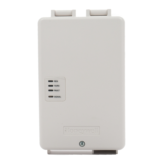
Page 23: Led And Wiring Information
LED and Wiring Information DESCRIPTION ON – Module is NOT registered with AlarmNet. (green) OFF – Module is registered with AlarmNet. FAST BLINK – Download session with Compass in progress. SLOW BLINK – In unison with yellow LED – Registration in progress. PERIODIC FLASH –... - Page 24 If an external cellular radio antenna is used, the antenna may be installed or replaced ONLY by a professional installer. TO THE INSTALLER For the CDMA-X, the external antenna must not exceed a maximum directional gain (including cable loss) of 3.2 dBi at 850 MHz and 2.3 dBi at 1900 MHz SUPPORT &...