
Related Manuals for Honeywell 7847i-E


Summary of Contents for Honeywell 7847i-E
- Page 1 Installation and Setup Guide Requires Compass Version 1.5.8.54A (or higher) for IP Downloading 800-19325 2/15 Rev B...
-
Page 2: Glossary
Glossary AES – Advanced Encryption Standard DHCP – Dynamic Host Configuration Protocol. Provides a mechanism for allocating IP addresses dynamically so that addresses can be reused when hosts no longer need them. DNS – Domain Name System. A distributed hierarchical naming system used to resolve domain names (e.g., www.yahoo.com) into numerical IP addresses (e.g., 204.17.25.1.). -
Page 3: Table Of Contents
Power Connections and Options .......................... 2-4 Ethernet Connections ............................. 2-4 Initial Power-Up Sequence ........................2-4 SECTION 3: Programming the 7847i/7847i-E ....................3-1 General Information ..............................3-1 Using a 7720P Programming Tool ......................3-1 Using the Control Panel Programming Mode ..................3-2 Programming Conventions ........................ - Page 4 SECTION 5: Programmer Keyboard Commands ..................5-1 Programmer Keyboard Commands ........................5-1 System Status Displays ........................... 5-2 Running Network Diagnostics on the 7847i-E ....................6-1 Possible Errors Running Network Diagnostics ..................6-2 Appendices ..............................A-1 Appendix A : Summary of LED Operation ......................A-1 Status Display Operation .........................
-
Page 5: Section 1: General Information
• About Private Network Application The 7847i-E transmits signals within a private network application to a 7810PC or 7810iR-ent receiver. Up to 300 7847i-E Intranet Communication Modules may be routed to a single receiver. For receivers: MX8000: UL/ULC. can be used for secondary reporting in ECP. Required for Zone Trigger or Passive Channel Security. -
Page 6: Encryption
Only ECP Mode has been approved for ULC installations. ECP and Zone Trigger have been approved for UL installations The 7847i-E provide four modes of operation so they can be used with various types of control panels, as summarized below: ECP Mode •... -
Page 7: Zone Trigger Mode
• Reports are sent in ADEMCO High-Speed format Module Supervision Features The 7847i-E provides the following types of supervision and module fault detection: • Network communication failure: In the event the receiver does not hear a supervisory message from the module within a specified time (“Supervision” option), it notifies the central station of a communication failure. -
Page 8: Programming For Ul864 Compliance
7847i-E Installation and Setup Guide Programming for UL864 Compliance The 7847i-E provides a programmable supervision features that allows the system to meet the UL864 Commercial Fire requirements. These requirements are in the following table. This product incorporates field-programmable software. In order for the product to comply with the requirements in the Standard for Control Units and Accessories for Fire Alarm Systems, UL 864, certain programming features or options must be limited to specific values or not used at all as indicated below. -
Page 9: Section 2: Mounting And Wiring
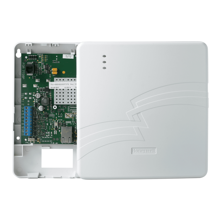
For Commercial Fire the communicator must be mounted to a single or double gang box. The 7847i-E must be mounted indoors. To mount the unit, see Figure 2 and complete the following steps: 1. Unpack the unit and detach the case back by pushing up into the two tabs located at the bottom of the 7847i-E module with the blade of a screwdriver while pulling the case back and case front apart. -
Page 10: Wiring The 7847I-E
Figure 3. Wiring a Vista for ECP Mode Wiring for Zone Trigger Mode To trip the zone on the 7847i-E in V+ trigger mode, the positive triggering voltage from the control panel must be within 2.0V-14V. Trigger levels above this range may cause permanent damage to the unit. -
Page 11: Wiring The Fault Relay
(-V) Trigger Notes for Trigger Mode with Non- Honeywell Controls: • Commercial Fire: a) Assign one zone (3-7) between the 7847i-E and triggering device for each of the following conditions: alarm, trouble, & supervisory events. See Summary of Connections diagram on inside back cover for wiring detail and refer to the control panel’s instructions for specific control panel wiring terminals. -
Page 12: Power Connections And Options
7847i-E Installation and Setup Guide Power Connections and Options Primary power for the 7847i-E is provided by the auxiliary power output of the control panel 9.6V –13.8V, typical, or other external power source. When calculating the total load on the auxiliary power output of the control panel, 20mA must be budgeted for the 7847i-E. -
Page 13: General Information
General Information To the control panel, the 7847i-E Intranet Communication Module, when in ECP Mode, is treated as a long-range radio device. The 7847i-E can be configured to deliver alarms via a Private LAN directly to a 7810PC or 7810iR-ent receiver. -
Page 14: Using The Control Panel Programming Mode
7847i-E Installation and Setup Guide Using the Control Panel Programming Mode Some control panels support programming of the 7847i-E through the control panel programming mode (e.g., Vista-128BP). If programming through the control panel, only the ECP Mode programming options are available. The "mode" questions will not be displayed, and the mode cannot be changed. - Page 15 Section 3: Programming the 7847i-E PROMPTS ENTRY OPTIONS DESCRIPTION then press the [Enter] key when prompted for the new password and its confirmation. [0-9, A-F, N, S, This prompt is displayed if [Y] was pressed in Prompt 4 or Enter Password T, X, Y] Enter a 4-digit password (0-9, A-F, N, S, T, X, Y).
- Page 16 Enter the 4-digit subscriber account number for the Primary Sub ID [0001-9999] primary central station, 0001-9999 (decimal). (????) In ECP mode, the 7847i-E communicates with the panel Device Address [01-30] as a communication (LRR) device. Enter the appropriate (03)_ ECP device address. For VISTA-10 and VISTA-20 series control panels, use address 03.
- Page 17 00 if you do not want the unit to alert the control panel of loss of contact with the network. The 7847i-E will alert the control panel of the loss of contact via a dedicated status message.
- Page 18 7847i-E Installation and Setup Guide PROMPTS ENTRY OPTIONS DESCRIPTION • (V+) Selects the triggering method for this zone input. Zn6 Trigger Type • (V–) (V+)_ Press the [space] key to scroll through choices. • (EOLR) UL: V+ must be set as inverted and V- as non-inverted...
-
Page 19: Ecp Status Codes
Alternative Zone Trigger Mode Zone Trigger Mode There are six input zones available on the 7847i-E. Zones 1 and 2 are located on TB1 pin 5 and are selectable for +V, –V, or EOLR modes, which can detect both pulsed and steady signals. - Page 20 7847i-E Installation and Setup Guide ZONE PROMPTS ENTRY OPTIONS DESCRIPTION TRIG. Y/N_ prompt. Press [Y] if you want to change the password. NOTE: To clear an existing password, without entering a new one, answer [Y] to the "Change Password?" prompt, then press the [Enter] key when prompted for the new password and its confirmation.
- Page 21 4204/ ZONE PROMPTS ENTRY OPTIONS DESCRIPTION 2-4204 TRIG. If 30 Day or Daily is selected, the 7847i-E will IP2 Supervision • 30 Day send a test alarm to the second CS IP within that 30 Day_ • Daily interval.
- Page 22 [00-99] IP Flt Time 7847i-E notifies the control panel that there is loss (60 mins)_ of contact with the network, or enter 00 if you do not want the unit to alert the control panel of loss of contact with the network. The unit will alert the control panel of the loss of contact via a dedicated status message.
- Page 23 Section 3: Programming the 7847i-E 4204/ ZONE PROMPTS ENTRY OPTIONS DESCRIPTION 2-4204 TRIG. During normal system operation the open Flt Rel ON Y/N [Y], [N] collector fault output will change states (open or (N)_ ground) on a fault condition. The change of state depends on whether (Y) or (N) is used during programming.
- Page 24 7847i-E zone causes a bell fault on the control panel, enable the "Trip Inputs 1or2" option. The 7847i-E reports an alarm on zone 1 (fire) when it detects a pulsed signal and an alarm on zone 2 (burglary) when it detects a steady signal.
- Page 25 Section 3: Programming the 7847i-E 4204/ ZONE PROMPTS ENTRY OPTIONS DESCRIPTION 2-4204 TRIG. [Y], [N] Use if the zone 1 and 2 connection to the control's Trip Inputs 1or2 bell output causes a bell fault on the control panel. w/Bell Out (N)_ NOTES: 1.
- Page 26 7847i-E Installation and Setup Guide 4204/ ZONE PROMPTS ENTRY OPTIONS DESCRIPTION 2-4204 TRIG. [Y], [N] Restore Zn2 Y/N Enables restore reporting for zone 2. (Y)_ [01-15] Defines the reporting delay in seconds for zone 2. Delay Zn2 (secs) ...
- Page 27 Section 3: Programming the 7847i-E 4204/ ZONE PROMPTS ENTRY OPTIONS DESCRIPTION 2-4204 TRIG. Reports alarms on zone 5 ONLY if the conditional [Y], [N] Rpt Zn5 ONLY if zone (zone 7 in zone trigger mode; zone 8 in 2-...
-
Page 28: Exiting Programming Mode
If critical configuration changes were made, such as the mode of operation, the 7847i-E will reset to ensure that the programmed features are enabled. Setting Factory Defaults To reset the programming options to factory-default values, press [ESC] at the "Exit Prog Mode?"... -
Page 29: Section 6: Registration
Registration Registering the 7847i-E Once you have initialized and programmed the 7847i-E, it must be registered to enable the account. An unregistered unit is indicated on the Status Display LEDs as: Status lit, Message slow blinking, and Fault not lit. The Internet Link may be lit or blinking. Refer to Appendix A for a detailed discussion of LED operation. - Page 30 Timed Out This prompt is displayed if the account number programmed in the Registration BAD 7847i-E is already being used for a different 7847i-E in the system. Account Exists! If a replacement is desired, enable Substitution Mode in the receiver.
-
Page 31: Section 5: Programmer Keyboard Commands
"x.x.xx" indicates the installed software Revision. Mm/dd/yy indicates month, day and year of the revision. MAC Address xxxxxxxxxxxx “xxxxxxxxxxxx” indicates the 7847i-E's unique MAC CRC xxxx identification number. "xxxx" indicates the MAC CRC number. This number is also found on the label on the module, as well as the label on the box. -
Page 32: System Status Displays
7847i-E Installation and Setup Guide DHCP (Dynamic Host Configuration Protocol) indicates DHCP server is performing satisfactorily. OK/BAD Press the [space] key to go to the Physical Link display. Run Network Diagnostic Test Testing Gateway Performs a set of network diagnostics that tests the integrity of the links between the unit and the various connection points (Redirs) to the receiver. - Page 33 Pressing [Y] resets the module (blank screen = reset complete). [↑] Registration Registering … Registers a programmed 7847i-E with the receiver. (UP arrow) Enter Program Mode [ENTER] Strt Prog Mode? Press [Y] to enter program mode; otherwise, press [N].
- Page 34 7847i-E Installation and Setup Guide...
-
Page 35: Running Network Diagnostics On The 7847I-E
Network Diagnostics Running Network Diagnostics on the 7847i-E The network diagnostic process tests the integrity of the links between the 7847i-E and the receiver to which it should report. To initiate the network diagnostics, press the [F] key on the 7720P. -
Page 36: Possible Errors Running Network Diagnostics
7847i-E Installation and Setup Guide The service at the receiver on CS IP 3 is functioning. See below for CSIP 3 possible errors that may occur at this stage of testing. Service OK If CS IP 2 and/or CS IP 3 are not programmed, display will read. -
Page 37: Appendices
• • • • • • • • • • • • • • • • • • • • • • • • • • • • • • • • • • • • • • • • • • • • • • • • • Appendix A: Summary of LED Operation Status Display Operation The 7847i-E Status Display has three LEDs used to indicate message and device status: • STATUS, green •... - Page 38 Figure 13. A Registered 7847i-E Status Display (A) and an Unregistered 7847i-E Status Display in Normal Operating State(B) The sequence below illustrates LED operation when 7847i-E transmits a message. Figure 14. LED Sequence for a Registered 7847i-E Message Transmission...
-
Page 39: Network Connectivity Display
Network Connectivity Display The Network Connectivity display can only be viewed with the cover removed. It is used as a visual indication of 7847i-E network activity. Figure 15. 7847i-E Network Connectivity Display The Network Connectivity Display consists of three LEDs. They function as follows:... -
Page 40: Mode And Status Led Display
7847i-E Installation and Setup Guide Mode and Status LED Display The Mode and Status LED Display consists of 4 LEDs. LED 1 (red LED on the left) will be off, LED 2 and 3 (yellow LEDs) indicate operation mode. LED 4 (1 green LED) displays Web connection status;... -
Page 41: Appendix B: Central Station Messages
Appendix B: Central Station Messages The following messages are sent by the 7847i-E module for the conditions listed below. Table 8. Central Station Messages ECP Mode ECP Mode Zone and 4204 Zone and 4204 Alarm Condition Alarm Code Restore Code... - Page 42 7847i-E Installation and Setup Guide...
-
Page 43: Appendix C: Ip Downloading
IP programming is enabled (Direct Wire Y/N), and that the ECP Device Address on which the unit communicates with the control panel as a keypad is entered (Keypad Address). Additionally, the 7847i-E must be connected by cable as shown below to the panels listed. - Page 44 7847i/7847i-E Installation and Setup Guide Prior to IP up/downloading over a Private LAN, setup of the Honeywell Compass Connect Server and Honeywell Compass downloader is required. Refer to the Compass Connect Server Installation and Setup Guide (K10178V1) and the Compass IP Downloading Supplement (K10441V1) for setup instructions.
-
Page 45: Appendix D: 7847I-E Code Updating
To initiate a code update, a compressed code file must be posted to on an IIS server on the same subnet as the 7847i-e. The compressed code file should have the extension .scz and the filename MUST include “7847ie”, otherwise the update will not be attempted. -
Page 46: Summary
7847i/7847i-E Installation and Setup Guide Upon successful completion of downloading the code file, the device sends a “Code Update Successfully Completed” message to the Central Station (R903 00 C803). Once the Code Update message is either delivered central station or the Old Alarm Time has expired for that message, the device will reset. - Page 47 7847i-E Summary of Connections TB1 Wiring for 7847i-E Communication Module 2 x 4204 Mode 4204 Mode Zone Mode ECP Mode Wire Color 12VDC 12VDC 12VDC 12VDC ECP IN ECP IN Z1/Z2 ECP IN ECP OUT ECP OUT ECP OUT NOT USED...
- Page 48 If an external cellular radio antenna is used, the antenna may be installed or replaced ONLY by a professional installer. TO THE INSTALLER For the 7847i-E, the external antenna must not exceed a maximum directional gain (including cable loss) of 3.2 dBi at 850 MHz and 2.3 dBi at 1900 MHz. DOCUMENTATION AND ONLINE SUPPORT For the latest documentation and online support information, please go to: https://mywebtech.honeywell.com/...