Honeywell UDC2300 Product Manual
Universal digital controller
Hide thumbs
Also See for UDC2300:
- Product manual (186 pages) ,
- User manual (82 pages) ,
- Replacement instructions (2 pages)

Related Manuals for Honeywell UDC2300


Summary of Contents for Honeywell UDC2300
- Page 1 UDC2300 Universal Digital Controller Limit Control Model Product Manual Doc. No.: 51-52-25-102 Last Revision Date: 1/01...
- Page 2 About This Document Abstract This document provides descriptions and procedures for the installation, configuration, operation, and troubleshooting of your UDC2300 Limit Controller. UDC2300 Limit Controller Product Manual 1/01...
- Page 3 Chassis Ground. Identifies a connection to the chassis or frame of the equipment shall be bonded to Protective Earth at the source of supply in accordance with national and local electrical code requirements. 1/01 UDC2300 Limit Controller Product Manual...
-
Page 4: Table Of Contents
Lock Set Up Group ........................24 Limit Set Up Group........................25 Input 1 Set Up Group ........................26 Options Set Up Group........................28 Communications Set Up Group ....................29 Alarms Set Up Group........................31 4.10 Configuration Record Sheet......................33 UDC2300 Limit Controller Product Manual 1/01... - Page 5 TROUBLESHOOTING/SERVICE ............... 53 Overview ............................53 Troubleshooting Aids........................54 Power-up Tests..........................56 Status Tests ..........................56 Background Tests......................... 57 Controller Failure Symptoms....................... 58 Troubleshooting Procedures ......................59 PARTS LIST......................63 Exploded View..........................63 INDEX ......................... 65 1/01 UDC2300 Limit Controller Product Manual...
- Page 6 Table 7-6 Troubleshooting Latching Output Relay Failure ___________________________________ 60 Table 7-7 Troubleshooting Alarm Relay Output Failure _____________________________________ 61 Table 7-8 Troubleshooting a Keyboard Failure ____________________________________________ 61 Table 8-1 Parts Identification __________________________________________________________ 63 Table 8-2 Parts Not Shown____________________________________________________________ 64 UDC2300 Limit Controller Product Manual 1/01...
- Page 7 Figures Figure 1-1 UDC2300 Operator Interface __________________________________________________ 2 Figure 2-1 Model Number Interpretation __________________________________________________ 5 Figure 2-2 Jumper Placements __________________________________________________________ 7 Figure 2-3 Mounting Dimensions (not to scale)_____________________________________________ 9 Figure 2-4 Mounting Method __________________________________________________________ 10 Figure 2-5 Composite Wiring Diagram __________________________________________________ 12...
- Page 8 UDC2300 Limit Controller Product Manual 1/01...
-
Page 9: Introduction
1 Introduction 1.1 Overview Introduction UDC2300 Limit Controllers accept input signals from any of several types of external sensors such as Thermocouples (T/Cs) and Resistance Temperature Detectors (RTDs). It conditions these signals, as necessary, to derive the equivalent Process Variable (PV) value that drives various circuits in the controller. -
Page 10: Ce Conformity (Europe)
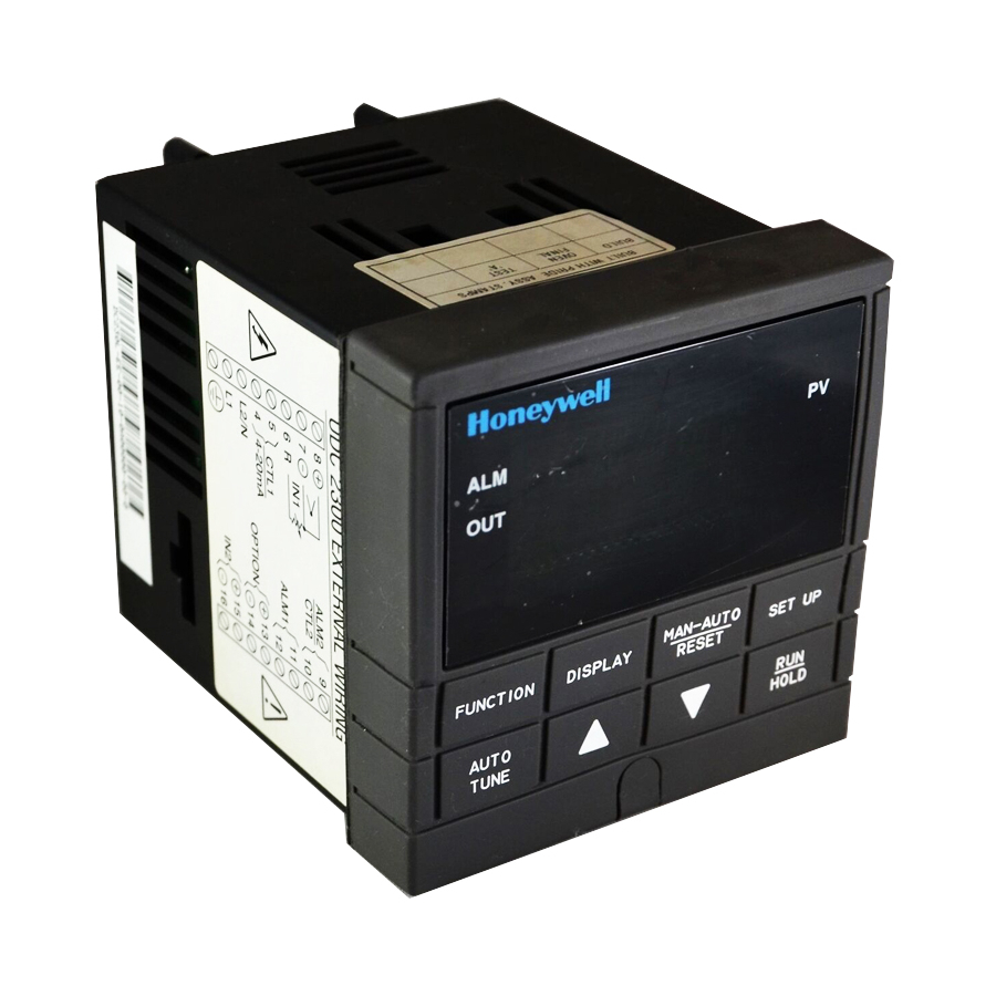
RESET AUTO TUNE HOLD Figure 1-1 UDC2300 Operator Interface 1.2 CE Conformity (Europe) This product is in conformity with the protection requirements of the following European Council Directives: 73/23/EEC, the Low Voltage Directive, and 89/336/EEC, the EMC Directive. Conformity of this product with any other “CE Mark” Directive(s) shall not be assumed. -
Page 11: Installation
2 Installation 2.1 Overview Introduction Installation of the UDC2300 consists of mounting and wiring the controller according to the instructions given in this section. Read the pre-installation information, check the model number interpretation, and become familiar with your model selections, then proceed with installation. -
Page 12: Table 2-1 Condensed Specifications
RTD, thermocouple, dc Millivolts, low level Conditions (Europe) signal, 4-20 mA, digital I/O, and computer interface circuits. Refer to 51-52-05-01, How to Apply Digital Instrumentation in Severe Electrical Noise Environments, for additional information. UDC2300 Limit Controller Product Manual 1/01... -
Page 13: Model Number Interpretation
1 _ = T/C, RTD, Radiamatic, mV, 0-5V, 0-20mA, 4-20mA 2_ = T/C, RTD, Radiamatic, mV, Volts, milliamps, 0-10 Volts Optional Input 2 _ 0 = None _ 1 = 0-5V, 1-5V, 0-20mA, 4-20mA Figure 2-1 Model Number Interpretation 1/01 UDC2300 Limit Controller Product Manual... -
Page 14: Preliminary Checks
See Table 2-3 for Limit Control Relay contact information, and Table 2-4 for Alarm Relay contact information. See Alarm Relay Caution Note, Page 8. Note: Solid State and Open Collector must have jumper set to N.O. (Normally Open). UDC2300 Limit Controller Product Manual 1/01... -
Page 15: Figure 2-2 Jumper Placements
NC (default) Input #1 S101 Position 1: thermocouple (default) Position 2: mV, Volt, RTD Output #1 W101 Position 3: not used Position 4: mA NO (Default) No jumper: 0 -10 volts Figure 2-2 Jumper Placements 1/01 UDC2300 Limit Controller Product Manual... -
Page 16: Limit Control And Alarm Relay Contact Information
Table 2-4 Alarm Relay Contact Information Unit Alarm Relay Variable NOT in Alarm State Variable in Alarm State Power Wiring Relay Indicators Relay Indicators Contact Contact N.O. Open Open N.C. Closed Closed N.O. Closed Open N.C. Open Closed UDC2300 Limit Controller Product Manual 1/01... -
Page 17: Mounting
Panel Cutout 3.780 -0.0 Max Panel 2.62 Max (2) with optional Thickness .945 rear cover .394 .103 90.7 3.57 Dimensions: Millimeters Inches 105.4 21.0 4.19 20751 .826 Figure 2-3 Mounting Dimensions (not to scale) 1/01 UDC2300 Limit Controller Product Manual... -
Page 18: Table 2-5 Mounting Procedure
Insert the prongs of the clips into the two holes in the top and bottom of the case. • Tighten both screws to secure the case against the panel. • Carefully slide the chassis assembly into the case, press to close, and tighten the screw. Replace the screw cover. UDC2300 Limit Controller Product Manual 1/01... -
Page 19: Wiring
Use Suppression Devices—For additional noise protection, you may want to add suppression devices at the external source. Appropriate suppression devices are commercially available. For additional noise information, refer to Document #51-52-05-01, How to Apply Digital Instrumentation in Severe Electrical Noise Environments. 1/01 UDC2300 Limit Controller Product Manual... -
Page 20: Wiring Diagrams
Supply Terminals See Figure 2-6 NOTE1: Electromechanical Relay Output – See Figure 2-8 Solid State Relay Output – See Figure 2-9 Open Collector Output – See Figure 2-10 24855 Figure 2-5 Composite Wiring Diagram UDC2300 Limit Controller Product Manual 1/01... -
Page 21: Figure 2-6 Mains Power Supply
Source specified. You must install it when you wire the controller before start-up. 1 24857 1 These inputs are wired differently than the UDC2000 Figure 2-7 Input 1 Connections 1/01 UDC2300 Limit Controller Product Manual... -
Page 22: Figure 2-8 Electromechanical Relay Output
Amp at 55°C. Customer should size fuse accordingly. See Figure 2-11 for Alarm Output Connections. See Table 2-3 and Table 2-4 for Limit Control and Alarm Relay Contact information. Figure 2-9 Solid State Relay Output UDC2300 Limit Controller Product Manual 1/01... -
Page 23: Figure 2-10 Open Collector Relay Output
See “Preliminary Checks” in this section of the Product Manual for details. Each SPST relay is rated at 5 A, 120 Vac and 30 Vdc, 2.5 A, 240 Vac. Figure 2-11 Alarm Output Connections 1/01 UDC2300 Limit Controller Product Manual... -
Page 24: Figure 2-12 External Interface Option Connections
Do not run these lines in the same conduit as AC power. D– 120 OHMS ON LAST LEG 1 AuxOut , Digital Input and Communications are mutually exclusive. Figure 2-12 External Interface Option Connections UDC2300 Limit Controller Product Manual 1/01... -
Page 25: Limit Control Application Diagram
POWER POWER LOAD LOAD The Limit Controller CANNOT protect The Limit Controller CAN protect against a failure of the Control relay against a failure of the Control relay Figure 2-13 Limit Controller Application Diagram 1/01 UDC2300 Limit Controller Product Manual... - Page 26 Installation UDC2300 Limit Controller Product Manual 1/01...
-
Page 27: Initial Start-Up
“TEST DONE” is displayed. Test Failures If one or more of these tests fail, a message indicating which test failed will appear in the lower display. Then, “DONE” will appear in the lower display. 1/01 UDC2300 Limit Controller Product Manual... -
Page 28: Operator Interface And Key Functions
When a key is pressed and the prompt KEYERR appears in the lower display, it will be for one of the following reasons: • parameter is not available, • not in Set Up mode, press [SET UP] key first, • key malfunction. UDC2300 Limit Controller Product Manual 1/01... -
Page 29: Configuration
4.3 Configuration Procedure 4.4 Lockout Group 4.5 Limit Group 4.6 Input 1 Set Up Group 4.7 Options Set Up Group 4.8 Communications Set Up Group 4.9 Alarms Set Up Group 4.10 Configuration Record Sheet 1/01 UDC2300 Limit Controller Product Manual... -
Page 30: Configuration Prompt Hierarchy
SDENAB SHDTIM PARITY BAUD TX DLY WS FLT UNITS LOOPBK A1S1VA A1S2VA A2S1VA A2S2VA A1S1TY A1S2TY A2S1TY A2S2TY ALARMS A1S1HL A1S1EV A1S2HL A1S2EV A2S1HL A2S1EV A2S2HL A2S2EV ALHYST ALARM1 BLOCK STATUS VERSON FAILSF TESTS UDC2300 Limit Controller Product Manual 1/01... -
Page 31: Configuration Procedure
It stores any changes you have made. If you do not press any keys for 30 seconds, the controller times out and reverts to the mode and display used prior to entry into Set Up mode. 1/01 UDC2300 Limit Controller Product Manual... -
Page 32: Lock Set Up Group
NONE – all parameters are read/write CAL - all parameters are read/write except Calibration CONF – configuration parameters are Read Only; no writes permitted +SP – Only the Lockout group is available for read/write. Setpoint value is Read Only. UDC2300 Limit Controller Product Manual 1/01... -
Page 33: Limit Set Up Group
SP - Setpoint - if configured the setpoint will be displayed in the upper display. “SP” will appear in the lower display. PROC - Process Variable - PV will be displayed in the upper display. 1/01 UDC2300 Limit Controller Product Manual... -
Page 34: Input 1 Set Up Group
NNMH RADI NNML 0-20 N90H 4-20 N90L available on FM Models 0-10 100m Transmitter XMITR1 Characterization Available on Linear actuations only. 100H Not available on FM 100L Models NNMH NNML N90H RADH N90L RADI UDC2300 Limit Controller Product Manual 1/01... - Page 35 For units powered by +24 Vdc, this configuration should be set to the AC Line frequency used to produce the +24 Vdc Supply. Failure to set this parameter properly can cause normal mode noise problems in the input readings. 1/01 UDC2300 Limit Controller Product Manual...
-
Page 36: Options Set Up Group
Low Scaling Factor 100PCT Auxiliary Output Value in Engineering Units High Scaling Factor Digital Input EXTERNAL RESET (DIGITAL INPUT) — resets EXTRST the latching relay on contact closure. DIS – Disable ENAB – Enable UDC2300 Limit Controller Product Manual 1/01... -
Page 37: Communications Set Up Group
Configurable response-delay timer allows you to TX_DLY Response Delay force the UDC to delay its response for a time period of from 1 to 500 milliseconds compatible with the host system hardware/software. Range of Setting: 1 to 500 milliseconds 1/01 UDC2300 Limit Controller Product Manual... - Page 38 The UDC does not have to be connected to the RS-485 link to perform this test. If it is connected, only one UDC2300 should run the loopback test at a time. The computer should not be transmitting on the link while the loopback test is active.
-
Page 39: Alarms Set Up Group
Select whether you want the alarm type chosen in Alarmx Setpoint HIGH AxSxHL prompt "AxSxTY" to alarm High or Low. State A1S1 X = 1 or 2 A1S2 Low Alarm A2S1 HIGH High Alarm A2S2 1/01 UDC2300 Limit Controller Product Manual... - Page 40 The alarm is suppressed until the parameter gets to the non- alarm limit or band. Alarm blocking affects both alarm setpoints. Disable Blocking Block Alarm 1 only Block Alarm 2 only BK12 Blocks both Alarms UDC2300 Limit Controller Product Manual 1/01...
-
Page 41: Configuration Record Sheet
HIGH EMIS _______ A1S2HL _______ HIGH FREQ _______ A2S1HL _______ HIGH DISPLY _______ A2S2HL _______ HIGH ALHYST _______ ALARM1 _______ BLOCK _______ OPTIONS AUXOUT _______ 0 PCT _______ 100 PCT _______ EXT RST _______ 1/01 UDC2300 Limit Controller Product Manual... - Page 42 Configuration UDC2300 Limit Controller Product Manual 1/01...
-
Page 43: Operating The Limit Controller
The following topics are covered in this section. TOPIC See Page 5.2 Operator Interface 5.3 Entering A Security Code 5.4 Lockout Feature 5.5 Monitoring The Limit Controller 5.6 How to Operate Your Limit Controller 5.7 Alarm Setpoints 1/01 UDC2300 Limit Controller Product Manual... -
Page 44: Operator Interface
NONE. Thereafter, that selected number must be used to change the lockout level from something other than NONE. Write the number on the Configuration Record Sheet in the configuration section so you will have a permanent record. UDC2300 Limit Controller Product Manual 1/01... -
Page 45: Lockout Feature
This will be your security code. 5.4 Lockout Feature Introduction The lockout feature in the UDC2300 is used to inhibit changes (via keyboard) of certain functions or parameters by unauthorized personnel. Lockout levels There are different levels of Lockout depending on the level of security required. These levels are: •... -
Page 46: Monitoring Your Limit Controller
You can press to change the value of this parameter. Timing out from lower display The normal variable display will automatically return in the upper display if the key is not pressed for 30 seconds. [DISPLAY] UDC2300 Limit Controller Product Manual 1/01... -
Page 47: Table 5-3 Error Messages
(blinking). The PV is indicated in the upper display. This will continue until the Out-of- Limit condition exists and you reset the latching relay using the [MAN-AUTO RESET] or through the Optional External Reset feature. The Limit Relay cannot be reset while a Limit condition exists. 1/01 UDC2300 Limit Controller Product Manual... -
Page 48: Operating Your Limit Controller
Refer to Section 4 - Configuration, subsection 4.5 Limit Parameters Set Up Group under SET UP prompt “LIMIT” and make your selection at FUNCTION prompt “POWRUP.” UDC2300 Limit Controller Product Manual 1/01... -
Page 49: Table 5-4 Using Contact Input Option
Lower Display = OPTIONS Access the Until you see: FUNCTION External Reset Upper Display = ENAB Prompt Lower Display = EXTRST Change a value [ ] [ ] To select ENAB in the upper display 1/01 UDC2300 Limit Controller Product Manual... -
Page 50: Alarm Setpoints
DE (Deviation) value = within Input 1 Span PV (Process variable) value = Within Input 1 range Change a value [ ] [ ] To change any alarm setpoint value in the upper display Return to Normal DISPLAY Display UDC2300 Limit Controller Product Manual 1/01... -
Page 51: Input Calibration
INPUT CALIBRATION MAY REQUIRE ACCESS TO HAZARDOUS LIVE CIRCUITS, AND SHOULD ONLY BE PERFORMED BY QUALIFIED SERVICE PERSONNEL. MORE THAN ONE SWITCH MAY BE REQUIRED TO DE-ENERGIZE UNIT BEFORE CALIBRATION. Failure to comply with these instructions could result in death or serious injury. 1/01 UDC2300 Limit Controller Product Manual... -
Page 52: Minimum And Maximum Range Values
–0.461 mV 47.513 mV Nicrosil Nisil (Nic) 0 to 3100 –18 to1704 –0.090 mV 20.281 mV 0 to 3100 –18 to1704 –0.092 mV 17.998 mV -300 to 700 –184 to371 –5.341 mV 19.097 mV UDC2300 Limit Controller Product Manual 1/01... -
Page 53: Preliminary Information
6.3 Preliminary Information Disconnect the Field Wiring Tag and disconnect any field wiring connected to the input 1 terminals on the rear of the controller. Input 1 Connections Figure 6-1 Input 1 Wiring Terminals 1/01 UDC2300 Limit Controller Product Manual... -
Page 54: Table 6-2 Equipment Needed
• Do not switch current sources OFF/ON while connected to the UDC2300 input. For Radiamatic inputs only, set Emissivity value to 1.0. See Section 4.6 – Configuration Set Up prompt INPUT1, function prompt EMISS. UDC2300 Limit Controller Product Manual 1/01... -
Page 55: Input 1 Set Up Wiring
Step Action Connect the thermocouple extension wires to the terminals for Input #1 as shown in Figure 6-3. Thermocouple Source 24873 Thermocouple Extension Wire Figure 6-3 Wiring Connections for Thermocouple Inputs Using Thermocouple Source 1/01 UDC2300 Limit Controller Product Manual... -
Page 56: Table 6-5 Set Up Wiring Procedure For Rtd Inputs
Connect the copper leads from the calibrator to the Input #1 terminals as shown in Figure 6-4. Place current source at zero before switching on. Do not switch current sources ON/OFF while connected to the UDC2300 input. Decade Resistance 24875... -
Page 57: Input 1 Calibration Procedure
Connect the copper leads from the calibrator to the Input #1 terminals as shown in Figure 6-6. Place current source at zero before switching on. Do not switch current sources ON/OFF while connected to the UDC2300 input. Volt Source 24877 Figure 6-6 Wiring Connections for 0 to 10 Volts 6.5 Input 1 Calibration Procedure... -
Page 58: Table 6-8 Input 1 Calibration Procedure
100 % range values. • Wait 15 seconds, and If … Then … you are calibrating a Thermocouple input go to step 4 you are calibrating other than a go to step 5 Thermocouple input UDC2300 Limit Controller Product Manual 1/01... -
Page 59: Restore Factory Calibration
High and Low Range Limits. Be sure to protect any field calibration from accidental overwrites by configuring the appropriate LOCKOUT selection after calibration. See the Section 4 - Configuration for specific instructions to set the lockout. 1/01 UDC2300 Limit Controller Product Manual... -
Page 60: Table 6-9 Restore Factory Calibration
Upper Display = Original Input Selection that matches your type of sensor. Lower Display = IN1TYP to return to Normal operating mode. Return to Normal DISPLAY Operation The factory calibration will be restored. If the problem is not corrected, contact the provider. UDC2300 Limit Controller Product Manual 1/01... -
Page 61: Troubleshooting/Service
• Overall Error Messages • Controller Failure Symptoms • Determining the Software Version Number Power-up Tests Status Tests Background Tests Controller Failure Symptoms Troubleshooting Procedures • Power Failure • Alarm Relay Output Failure • Keyboard Failure 1/01 UDC2300 Limit Controller Product Manual... -
Page 62: Troubleshooting Aids
Troubleshooting/Service Installation related problems Read the Installation section in this manual to make sure the UDC2300 has been properly installed. The installation section provides information on protection against electrical noise, connecting external equipment to the controller, and shielding and routing external wiring. -
Page 63: Table 7-1 Procedure For Identifying The Software Version
Upper Display = READ SET UP STATUS Lower Display = STATUS Set Up Group Read the software FUNCTION You will see: version Upper Display = Software version number Lower Display = A2xx Limit Controller 1/01 UDC2300 Limit Controller Product Manual... -
Page 64: Power-Up Tests
Set Up Group Read the test FUNCTION You will see: results Upper Display = NO or YES YES indicates a failure Lower Display = FAILSF FUNCTION Upper Display = PASS or FAIL Lower Display = TEST UDC2300 Limit Controller Product Manual 1/01... -
Page 65: Background Tests
Troubleshooting/Service Background Tests Introduction The UDC2300 performs ongoing background tests to verify data and memory integrity. If there is a malfunction, an error message will be displayed (blinking) in the lower display. In the case of simultaneously malfunctions, the messages will appear in sequence in the lower display. -
Page 66: Controller Failure Symptoms
Displayed Controller Output Output disagrees with disagrees with controller displayed output output External Alarm Malfunction in function does alarm output not operate properly Display does not function when a key is pressed Keyboard Malfunction UDC2300 Limit Controller Product Manual 1/01... -
Page 67: Troubleshooting Procedures
Failure to comply with these instructions could result in death or serious injury. Equipment needed You will need the following equipment in order to troubleshoot the symptoms listed in the tables that follow: • Calibration sources – T/C, mV, Volt, etc. • Voltmeter 1/01 UDC2300 Limit Controller Product Manual... -
Page 68: Table 7-5 Troubleshooting Power Failure Symptoms
Listen for the click of the relay as the setpoint is moved above or below the PV. Check the Latching Relay Refer to subsection 2.4 Limit Control and Alarm jumper position (NO or NC). Relay Contact Information for Relay Contact information. UDC2300 Limit Controller Product Manual 1/01... -
Page 69: Table 7-7 Troubleshooting Alarm Relay Output Failure
Refer to Section 4 – Configuration. the security code. Using “1000” as a security code number will override the 4-digit code previously entered. Replace the display/keyboard if Installation instructions supplied with new any keys are not functioning. display/keyboard. 1/01 UDC2300 Limit Controller Product Manual... - Page 70 Troubleshooting/Service UDC2300 Limit Controller Product Manual 1/01...
-
Page 71: Parts List
Exploded View Introduction Figure 8-1 is an exploded view of the UDC2300 Limit Controller. Each part is labeled with a key number. The part numbers are listed by key number in Table 8-1. Parts not shown are listed in Table 8-2. -
Page 72: Table 8-2 Parts Not Shown
30756764-002 Rear Terminal Cover Kit 30756018-001 SS Relay 10 Amp (external) 30756725-501 SS Relay 1 Amp (internal) 30754465-501 0-10 Volt Input resistor assembly (100K pair) 30754142-003 Terminal Strip Assembly 30755306-501 Electro-mechanical Relay (5 Amp) UDC2300 Limit Controller Product Manual 1/01... -
Page 73: Index
Control/Alarm Circuit Wiring, 11 Input 1 Wiring Terminals, 45 Controller Failure Symptoms, 58 Input Calibration, 43 Controller Grounding, 11 Input I Jumper Placement, 6 Installation, 3 Installation Related Problems, 54 Internal Jumper (W101) For Control, 6 1/01 UDC2300 Limit Controller Product Manual... - Page 74 Normal Display, 25 Software Version Number, 55 Solid State Relay Output, 14 Sp High Limit, 25 Sp Low Limit, 25 Specifications, 4 Start Up, 19 Station Address, 29 Status Tests, 56 Suppression Devices, 11 UDC2300 Limit Controller Product Manual 1/01...
- Page 75 Millivolts, Or Volts (Except 0 To 10 Volts), 49 Troubleshooting Procedures, 59 Wiring Connections For Rtd (Resistance Troubleshooting/Service, 53 Thermometer Device), 48 Type Of Limit Controller, 25 Wiring Diagrams, 12 Udc2300 Limit Controllers, 1 Upscale Burnout, 27 1/01 UDC2300 Limit Controller Product Manual...
- Page 76 Index UDC2300 Limit Controller Product Manual 1/01...